Unit - 1
Magnetic fields and magnetic circuits
The MMF is defined as the work done in moving the unit magnetic pole (1weber) once around the magnetic circuit.
The magnetomotive force (MMF) is required to drive the magnetic flux in the magnetic circuit. The magnetic pressure, which sets up the magnetic flux in the circuit as called Magnetomotive Force. The SI unit of MMF is Ampere-turn (AT), and their CGS unit is G (gilbert). The MMF for the inductive coil shown in the figure below is expressed as
F=NI
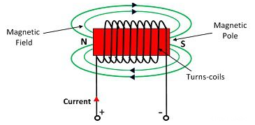
Fig 1 MMF
The strength of the MMF is equivalent to the product of the current around the turns and the number of turns of the coil.
Magnetic Flux:
The number of magnetic lines of forces set up in a magnetic circuit is called Magnetic Flux. It is analogous to electric current, I in an electric circuit. Its SI unit is Weber (Wb) and its CGS unit is Maxwell. It is denoted by φB.
ΦB=B.S
ΦB=B.S Cos
B – the magnitude of the magnetic field
S – area of surface
θ – angle between the magnetic field lines and perpendicular distance normal to the surface area
Magnetic flux for a closed surface
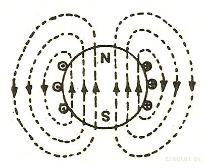
Fig 2 Magnetic lines of forces
ΦB= =0
=0
Magnetic flux for open surface is
E=
E=
E – electromotive force
v – velocity of the boundary
E – electric field
B – magnetic field
øB - magnetic flux through the open surface
The magnetic flux through a closed surface is always zero, but in the open surface, it is not zero.
Magnetic Reluctance:
The obstruction offered by a magnetic circuit to the magnetic flux is known as reluctance.
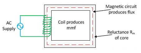
Fig 3 Reluctance
S=
l – the length of the conductor
μo – permeability of vacuum which is equal to 4π Χ10-7 Henry/metre.
μr – relative permeability of the material.
A – cross-section area of the conductor.
Its SI unit is AT / Wb (ampere-turns / Weber)
Magnetic Inductance:
The ability of an inductor to store energy in the form of magnetic field (and consequently to oppose the change in current) is called inductance. It is measured in the units of Henry(H).
Key takeaway
ΦB=B.S Cos
S=
Example
Que) A laminated soft iron ring of relative permeability 800 has a mean circumference of 600mm and a cross sectional area of 400mm2. A radial air gap of 1mm width is cut in the ring which is wound with 800 turns. Calculate the current required to produce an air gap flux of 0.5mWb if leakage factor is 1.2 and stacking factor 0.9.
Sol: Required Ampere turn =  gSg+
gSg+  iSi
iSi
= +
+ 
Air gap flux  s=0.5mWb
lg=1mm=1x10⁻³m
Ag=400mm2=400x10-6
Flux in iron ring  i=1.2x0.5x10-3=0.6mWb
Net cross-sectional area = Ai x stacking factor=400x10-6 x 0.9=360x10-6
Total AT required= +
+  = 994.72
I=A/N=994.72/800=1.24A
Que) An iron ring has X-section of 4cm2 and a mean diameter of 25cm. An air-gap of 0.3mm has been cut across the section of the ring. The ring is wound with a coil of 220 turns through which a current of 2A is passed. If the total magnetic flux is 0.24mWb, find relative permeability of iron?
Sol: φ=0.24mWb
A=4cm2=4 x 10⁻⁴
B= φ/A=0.24 x 10-3/4 x 10-4=0.6Wb/m2
AT for iron ring=H x l=(B/ )/l=(0.6/
 x
x ) x 0.25=1.19 x 10⁵/
AT for air gap= H x l= (B/ /l= (0.6/
 x 0.3x10-3=143.24
Total AT required= (1.19 x 10⁵/ +143.24
Total AT provided=220 x 2=440
Therefore,
(1.19 x 10⁵/ +143.24=440
 = 400.99
The law states that the mmf around a closed path is equal to the current enclosed by the path. The law cab be studied for
a) MMF around long straight conductor:
Let the conductor carry current of I amperes. The magnetic field consists of circular line of forces having their plane perpendicular to the conductor. If a unit pole is place at radius r, then work done to move the pole once round the conductor against this force is
Mmf= force x distance= I
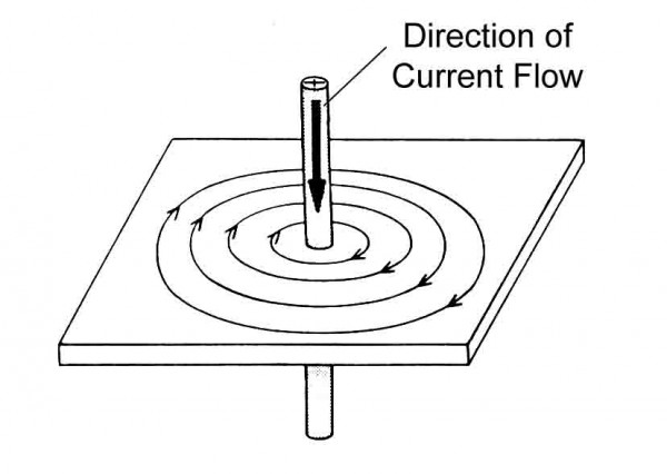
Fig 4 MMF around Long Straight Conductor
I= H x 2 r
r
H=I/2 r
r
For N conductors
H=NI/2 r (A/m)
B= μoH
B= μo NI/2 r (Wb/m2 or tesla)
b) Magnetic field strength of long solenoid:
The magnetic field along the solenoid is H. The ampere turns linked with the path are NI. Then according to Ampere’s Law
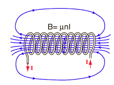
Fig 5 Magnetic field along the solenoid
H x l=NI
H=NI/l (A/m)
B= μoH
B=μoNI/l (Wb/m2 or tesla)
Boit-Savart Law:
The expression for the magnetic field strength dH produced at point P for small length dl of a conductor carrying current of I amperes is given as
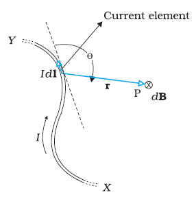
Fig 6 magnetic field strength dH produced at point P
dH= A/m
A/m
dB0= μo  Wb/m2
Wb/m2
Key takeaway
B= μo NI/2 r
r
Biot Savart Law
dH= A/m
A/m
dB0= μo  Wb/m2
Wb/m2
Example
Sol: H=I/2 r
r
=250/2 x 0.04=994.71 AT/m
B= μoH
=4 x10-7x994.71=1.25x10⁻³ Wb/m2
Sol: Value of h at centre of square will be H= =
=  =144 AT/m
Value of H at the centre of circle is H=I/2 r
r
=125.6AT/m
Bar Magnet:
All magnets have two regions called magnetic poles with the magnetism both in and around a magnetic circuit producing a definite chain of organised and balanced pattern of invisible lines of flux around it. These lines of flux are called as the magnetic field of the magnet. At each end of a magnet is a pole. Magnetic poles are always present in pairs, there is always a region of the magnet called the North-pole and there is always an opposite region called the South-pole. The lines which go to make up a magnetic field showing the direction and intensity are called Lines of Force or Magnetic Flux and represented as Phi (Φ).
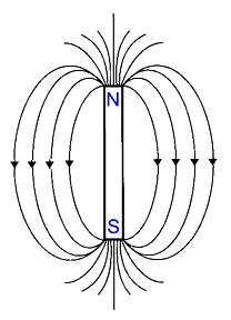
Fig 7 Bar Magnet
Like poles of the magnet repel each other and unlike poles attract each other.
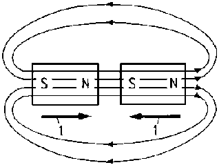
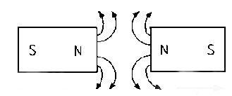
Fig 8 Magnetic Lines of Forces
Magnetic flux density =Magnet flux/Area
B= A Tesla
Current carrying coil:
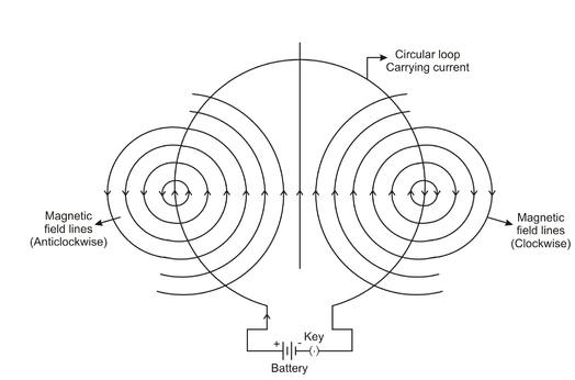
Fig 9 Magnetic Field Lines are Concentric Circles
The magnetic field lines are concentric circles at every point of a current carrying circular loop. The direction of magnetic field of every section of the circular loop can be found by using the right-hand thumb rule.
Factors affecting the strength of magnetic field
Key takeaway
In a bar magnet like poles repel each other and opposite poles attract each other.
Example
Sol: Area= r2
r2
Diameter=2r
r=14/2=7cm=0.07m
Area=3.14 x 0.072=0.0154m2
Flux Density B== A=0.013/0.0154=0.843 Tesla
Sol: Flux Density B= A
A
A=  B=0.02/0.5=0.04 m2
Area= r2
r2
r=0.113m
A highly permeable substance like ferromagnetic materials allow the magnetic lines of forces to pass through them easily. When a ferromagnetic material is placed in the magnetic field the magnetic lines of forces are concentrated inside the substance.
The magnetic permeability of a material is not constant, and for a given temperature, it changes based on the intensity of the applied external magnetic field (H). The relative aspect of permeability is more apparent when illustrated with a graph depicting a material’s permeability relative to the applied external field.
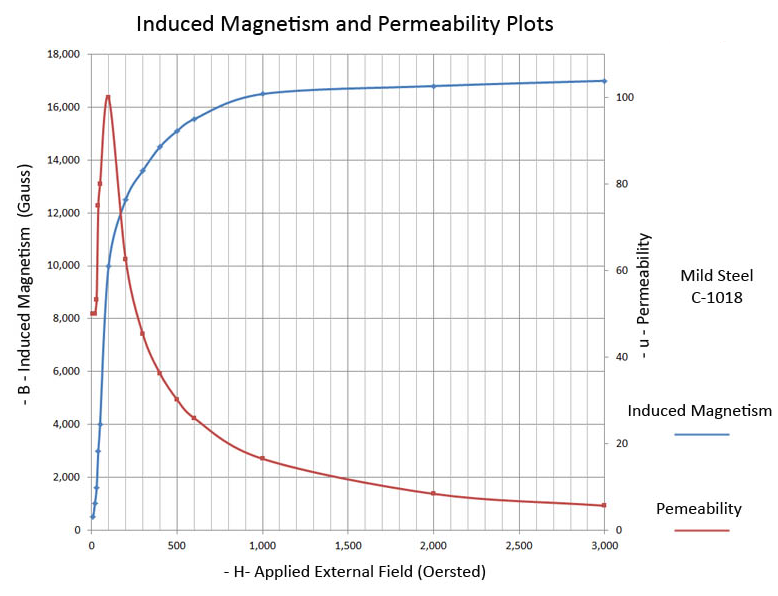
Fig 10 B-H Curve
Oftentimes, technical books will list a material’s magnetic permeability as a constant, but this is far from accurate and is very misleading. For instance, above figure is a plot for mild Steel C-1018, and it illustrates the Induced Magnetism (G) for various applied Field Strength levels (H). It also depicts the corresponding magnetic permeability at each applied field strength level. The permeability for C-1018 may be advertised as 100 (in the CGS unit system), but this is the peak value, and it is less than 20 over most of the curve.
A material’s permeability is important, because it allows one to anticipate the performance of a magnet when used in a design. For instance, a customer may want to pick up automobile exhaust tubing with a magnetic end effector on a robot-arm. When the tube is made from an aluminized mild steel alloy the magnet handling device may work just fine; however, when the tube is 410 SS, the tube may be dropped. The force of attraction between the handling magnet and the tube is greater with the aluminized mild steel than the 410 SS because the mild steel has a higher permeability than the 410 SS.
Key takeaways
A ferrous material is attracted to a permanent magnet because the permanent magnet induces magnetism within the ferrous material. The permanent magnet’s field and the newly induced field in the ferrous part interact and attract.
Magnetic Permeability is the characteristic of a material which represents the establishment of an induced internal magnetic field by an external magnetic field. The magnetic permeability is the proportionality between the Induced Field (B) and the applied Field Strength (H).
References: