Unit - 2
Electromagnetic force and torque
In a magnetic circuit, this field is represented by magnetomotive force. It is analogous to the electromotive force in electrical circuit. This field is responsible to “set up” certain flux, which in turn gives rise to certain flux density B. Note that, here H is cause and B is its effect. The amount of flux which can be setup in a material is determined by an inherent property of the material, called as permeability, denoted by µ.
B = µH
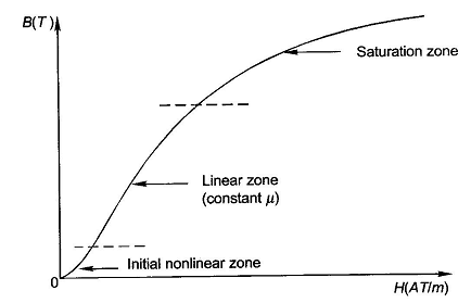
When external magnetic field H is applied to a material, all the domains align in a particular direction, setting up net flux in the material. Due to domain alignment B (i.e., the magnitude of B) increases. However, after a certain value of B, the slope of B − H curve starts reducing as shown in Figure below

Fig1: Magnetization curve
B-H Curve:
We cannot measure B and H directly. Further if we have transformer, we only have terminal measurements are with us. Hence, it is required to process the signals to get values of B and H. From Faraday’s law, V = N dφ/dt. Also, B is directly proportional to flux φ.

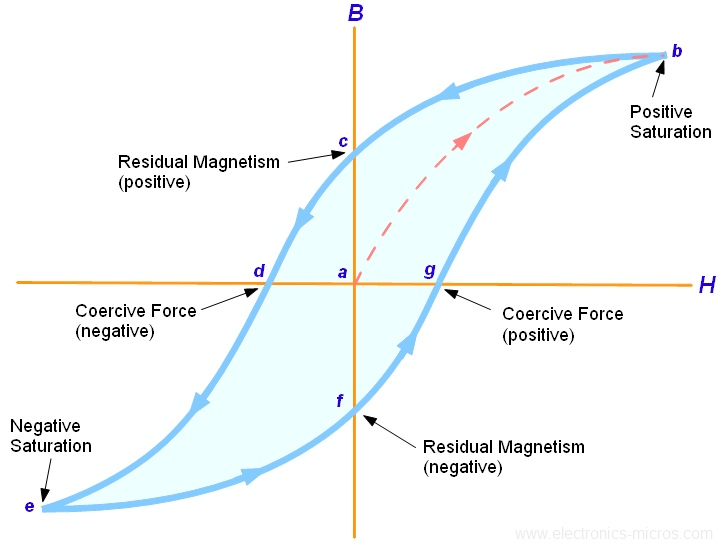
Fig 2: B-H curve
The lag or delay of a magnetic material known commonly as Magnetic Hysteresis. The Magnetic Hysteresis loop above, shows the behaviour of a ferromagnetic core graphically as the relationship between B and H is non-linear. Initially both B and H will be at zero, point 0 on the magnetisation curve.
If the magnetisation current, i is increased in a positive direction to some value than the magnetic field strength H increases linearly with i and the flux density B also increases (curve from point 0 to point a) as it heads towards saturation.
Now if the magnetising current in the coil is reduced to zero, the magnetic field circulating around the core also reduces to zero. However, the coils magnetic flux will not reach zero due to the residual magnetism present within the core and this is shown on the curve from point a to point b.
To reduce the flux density at point b to zero we need to reverse the current flowing through the coil. The magnetising force which must be applied to null the residual flux density is called a “Coercive Force”. This coercive force reverses the magnetic field re-arranging the molecular magnets until the core becomes unmagnetized at point c.
An increase in this reverse current causes the core to be magnetised in the opposite direction and increasing this magnetisation current further will cause the core to reach its saturation point but in the opposite direction, point d on the curve.
This point is symmetrical to point b. If the magnetising current is reduced again to zero the residual magnetism present in the core will be equal to the previous value but in reverse at point e.
Again, reversing the magnetising current flowing through the coil this time into a positive direction will cause the magnetic flux to reach zero, point f on the curve and as before increasing the magnetisation current further in a positive direction will cause the core to reach saturation at point a.
Then the B-H curve follows the path of a-b-c-d-e-f-a as the magnetising current flowing through the coil alternates between a positive and negative value such as the cycle of an AC voltage. This path is called a Magnetic Hysteresis Loop.
Key takeaway
The lag or delay of a magnetic material known commonly as Magnetic Hysteresis.
i) Linear Network: The ohm’s law is applicable in these types of networks. They consist of elements such as R, L and C which are always constant with respect to change in time voltage temperature etc. They follow law of superposition.
ii) Non-Linear Network: These networks do not follow superposition theorem and the circuit parameters changes with time voltage temperature etc.
As we already know that the current through the inductive coil gradually changes from zero to maximum value I, Then, this change is opposed by the self-induced emf produced. The energy is required to overcome this opposition. The value to value of energy stored will be
Let i=instantaneous value of current
E= induced emf at that instance=Ldi/dt
Work done in time dt is
dW=eidt=L  i dt=L i dt
Total work done will be
 =
= =LI2
=LI2
W= LI2
LI2
The work is stored as the energy of the magnetic field. Therefore, we have
E= LI2 Joules
Rate of change of stored energy:
As E= LI2
LI2
 =
= [L.2.I.
  + I2
+ I2  ]=
]= I2
I2 
Key takeaway
The work is stored as the energy of the magnetic field. Therefore, we have
E= LI2 Joules
Example
Que) An iron wire ring of 15 cm mean diameter having a cross-section of 90cm2 is wound with 400 turns of wire. Calculate the exciting current required to establish a flux density of 1Wb/m2 if relative permeability of iron is 1000. What is the value of energy stored?
Sol: B=
1=4 x
x  x 1000 x 400 x I/0.15
I=0.94A
L= AN2/l=4
 x
x  x 1000 x (90x 10-4) x (400)2/0.15
 =3.84H
E= LI2
LI2
= x 3.84 x (0.94)2=1.696J
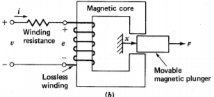
Consider a singly excited linear actuator as shown below.
R: winding resistance.
V: terminal voltage applied to the excitation winding
i: excitation winding current
The position of the movable plunger x, and the force acting on the plunger F with the reference direction chosen in the positive direction of the x axis, as shown in the diagram.

Fig 3 Force on movable magnet plunger
After a time, interval dt the plunger is moved for a distance dx under the action of the force F. The mechanical work done by the force acting on the plunger during this time interval is
dWm=Fdx
The amount of electrical energy that has been transferred into the magnetic field and converted into the mechanical work during this time interval can be calculated by subtracting the power loss dissipated in the winding resistance from the total power fed into the excitation winding as
dWe=dWf+dWm
dWe= vidt-Ri2dt
e= =v-Ri
=v-Ri
dWf= dWe- dWm=eidt-Fdx
=i -Fdx
-Fdx
From the above equation, we know that the energy stored in the magnetic field is a function of the flux linkage of the excitation winding and the position of the plunger. Mathematically, we can also write
dWf( x) =
x) = +
+
From above two equations
i=
F=-
The energy stored in magnetic field is given as
 =
= (
( d
d
For magnetically linear system  =
= 
The force acting on plunger will be F=-
 =
=  i2
i2 
Hence above equation shows the value of force as a partial derivative of stored energy with respect to position of a moving element
Key takeaway
The force acting on plunger will be F=-
 =
=  i2
i2 
For torque equation deriving with reference to the above section we can write
dWe=id -Td
-Td
The energy stored in magnetic field is given as
 =
= (
( d
d
i=
T=-
The energy stored in magnetic field is given as
 =
= (
( d
d
For magnetically linear system  =
= 
The Torque acting will be T=-
 =
=  i2
i2 
Key takeaway
The above equation is the required value of torque as a partial derivative of stored energy with respect to angular position of a rotating element.
Galvanometer coil
A moving coil galvanometer is an instrument which is used to measure electric current. A current-carrying coil when placed in an external magnetic field experiences magnetic torque. The angle through which the coil is deflected due to the effect of the magnetic torque is proportional to the magnitude of current in the coil. The moving coil galvanometer is made up of a rectangular coil that has many turns and it is usually made of thinly insulated or fine copper wire that is wounded on a metallic frame.

Fig 4 Galvanometer
The coil is free to rotate about a fixed axis. A phosphor-bronze strip that is connected to a movable torsion head is used to suspend the coil in a uniform radial magnetic field. A cylindrical soft iron core is symmetrically positioned inside the coil to improve the strength of the magnetic field and to make the field radial. The lower part of the coil is attached to a phosphor-bronze spring having a small number of turns. The other end of the spring is connected to binding screws.
We know that torque τ = force x perpendicular distance between the forces
τ = F × b
Substituting the value of F, we already know,
Torque τ acting on single-loop of the coil = BIl × b
Where lx b is the area A of the coil,
Hence the torque acting on n turns of the coil is given by
τ = nIAB
The magnetic torque thus produced causes the coil to rotate, and the phosphor bronze strip twists. In turn, the spring S attached to the coil produces a counter torque or restoring torque kθ which results in a steady angular deflection.
Under equilibrium condition:
kθ = nIAB
Here k is called the torsional constant of the spring (restoring couple per unit twist). The deflection or twist θ is measured as the value indicated on a scale by a pointer which is connected to the suspension wire.
θ= (nAB / k) I
Therefore θ ∝ I
The quantity nAB / k is a constant for a given galvanometer. Hence it is understood that the deflection that occurs the galvanometer is directly proportional to the current that flows through it.
Relay contact:
The relay contacts are opened or closed by a magnetic force. Basic parts and functions of electromechanical relays include:

Fig 5 Relay
Relays have the energizing circuit and the contact circuit. The coil is on the energizing side and the relays contacts are on the contact side. When a relays coil is energized, current flow through the coil creates a magnetic field. The magnetic coil attracts a ferrous plate, which is part of the armature. One end of the armature is attached to the metal frame, which is formed so that the armature can pivot, while the other end opens and closes the contacts. Contacts come in a number of different configurations, depending on the number of Breaks, poles and throws that make up the relay
Lifting magnet:
A high-powered magnetic device that’s used to lift objects. Also known as a portative electromagnetic, it allows workers to easily handle otherwise heavy objects. Permanent lifting magnets are composed of magnet materials and steel parts which build a path through which the magnetic flux goes from the magnet materials to ferromagnetic load to be lifted. The permanent lifting magnet has two magnetic sources, one is in the main body and another is in the rotor. When the two magnetic sources are at same magnetic direction the lifting magnet project magnetic flux to a ferromagnetic load underneath its poles. In contrast, when the two magnetic sources are at opposite magnetic direction, they absorb each other’s energy and no magnetic flux can go out from the lifting magnet.
Rotating element with eccentricity or saliency:
Three types of machine eccentricities: static, dynamic and mixed
Static: This is the state where the rotor axis is shifted from the stator axis and the rotor turns around the rotor axis. This fault is most easily dealt with flux. One has to just define the required mechanical sets which tells whether rotor is stationary or not.
Dynamic This is the state where the rotor axis is shifted from the stator axis and the rotor turns around the stator axis. This fault is also easy to model with Flux. One has just to define mechanical values which tells either its fixed or the rotor axis is shifted form stator.
Mixed: This is the state where the rotor axis is shifted from the stator axis and the rotor turns around both its axis with velocity ω1 and around the stator axis with velocity ω2. Often, if we know ω1, ω2 is difficult to define. This is the most difficult point in the modelling of mixed eccentricity.
Key takeaway
The galvanometer is not affected by a strong magnetic field. They have high torque to weight ratio. They are very accurate and reliable. They have uniform scales.
References: