Unit - 4
DC machine - motoring and generation
Generating Action
The basic circuit model for a dc machine is shown below:
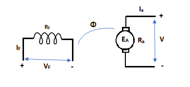
Fig 1 DC Machine
The machine operates in generating mode when the armature current is in the direction of induced emf Ea.
V = Ea – Ia Ra Ea> V
Pmech = Ea Ra = Pelect
The output power,
P0 = VIa
EaIa – VIa = Ia2 Ra
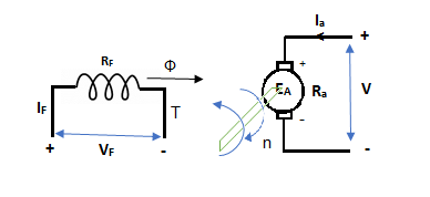
Fig 2 Torque Generated
In this mode, the torque of electromagnetic origin is in opposite direction of rotation of armature.
[Pmech]gross = Shaft power = [Pmech]net + Rotational loss.
Motoring Action
As the induced EMF (in the armature due to the field connections) due to residue magnetism destroys the residue magnetism giving a negative feedback. So, to overcome this we can either reverse the field connections to armature or the direction of rotation can be reversed. But in large generators with permanent connections, the problem is solved by exciting the filed temporarily from a battery source.
In this mode, the armature current Ia flows opposite to the emf induced i.e., Ea. The basic circuit showing this mode is below:
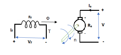
Fig 3 DC Machine
(Ea – Eb) is called as back emf here as it opposes the armature emf.
V = Ea + IaRa
Electrical power connected to mechanical form
Pelec / net = EaIa
Power input, Pi = V Ia
V Ia – EaIa = Ia2Ra = armature copper loss.
The back emf is given as
Eb = 
Key takeaway
V = Ea – Ia Ra
Eb = 
It is the curve which relates the field current and armature terminal voltage on open circuit. For generating mode, we already know that generated emf is directly proportional to flux per pole and speed of armature.

The circuit is given below-
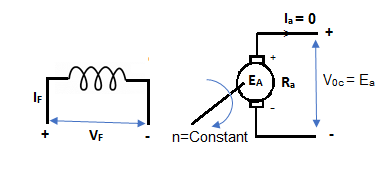
Fig 4 DC Machine
From above figure,
Voc = Ea
The magnetization characteristic of dc machines is determined by measuring Voc at rated armature speed and gradually increasing If from zero till Voc reaches above rated value of machine.
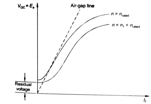
Fig 5 Open Circuit Voltage
From above curve, we can conclude
1) A small residue voltage is present when field is unexcited.
2) The field current If increases from initial value, the flux and hence generated emf is increased.
3) The air-gap line is the magnetic behaviour of machines air-gap. The iron being unsaturated in this region consumes negligible power.
4) The open circuit cost is conducted by exciting the main field winding.
5) The equivalent main field current is given

Nf, main field turns
If, main field current
Nse, main series turn
Ise, main series current
As induced emf is reduced by demagnetizing effect of armature reaction in saturation region of curve. So, the modified magnetization characteristics are shown below with Ia = 0, Ia = Ia1, Ia = Ia2.
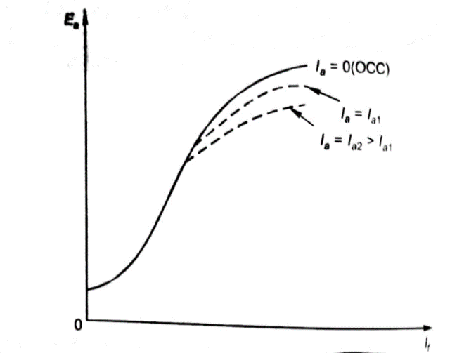
Fig 6 Open Circuit Characteristics
B. Self-excitation
The magnetization curve relates the no load voltage to the field current. The circuit is shown below
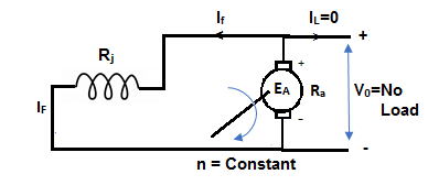
Fig 7 Self-Excited DC Motor
The field is introduced after the armature has been brought to rated speed. Just the moment after switching on the field, residue armature voltage exists which causes small value of field current. A fine steady state value is attained because of the saturation state of machines magnetic circuit. The magnetization curve is shown below:
The current in armature can be related to field current as
Ia = If
V = Ea- If Ra
In this case, field current is very small, so
V ≈ Ea (If) [magnetization characteristic]
For field current,
V = If Rf
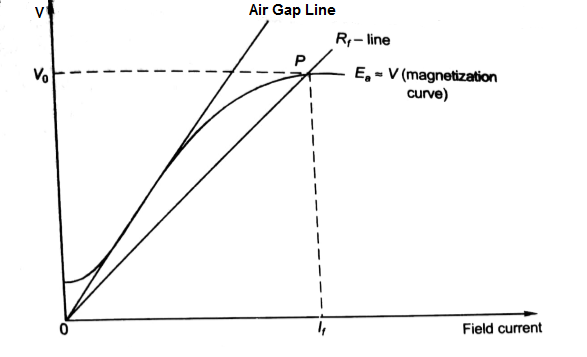
Fig 8 Magnetisation Curve
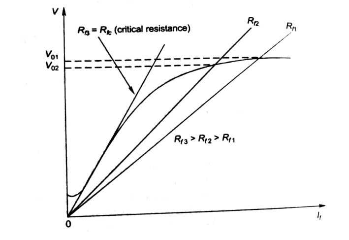
Fig 9 Critical Resistance
Key takeaway
At critical Speed, the generator fails to excite.
The magnetization characteristic of dc machines is determined by measuring Voc at rated armature speed and gradually increasing If from zero till Voc reaches above rated value of machine.
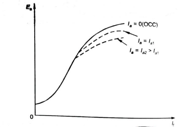
Fig 10 Open Circuit Characteristics
From above curve, we can conclude
1) A small residue voltage is present when field is unexcited.
2) The field current If increases from initial value, the flux and hence generated emf is increased.
3) The air-gap line is the magnetic behaviour of machines air-gap. The iron being unsaturated in this region consumes negligible power.
4) The open circuit cost is conducted by exciting the main field winding.
5) The equivalent main field current is given

Nf, main field turns
If, main field current
Nse, main series turn
Ise, main series current
As induced emf is reduced by demagnetizing effect of armature reaction in saturation region of curve. So, the modified magnetization characteristics are shown below with Ia = 0, Ia = Ia1, Ia = Ia2.
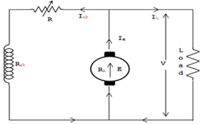
Fig 11 Open Circuit Voltage
Key takeaway
1) The field current If increases from initial value, the flux and hence generated emf is increased.
2) The air-gap line is the magnetic behaviour of machines air-gap. The iron being unsaturated in this region consumes negligible power.
In a DC motor when the armature rotates the conductors also rotate and hence cut the flux. According to the law of electromagnetic induction, the induced EMF is in the opposite direction (by Fleming’s Right hand rule) to the applied voltage. As it has opposite direction so it is referred to as back EMF (Eb).
Let φ = Flux /pole
P = Number of poles
Total flux produced by poles = φ x P
Time taken to complete one revolution= 60/N
N= speed of armature conductor in rpm
Let e be the induced emf of the armature conductor.
By Faraday’s Law e=
Induced emf in one conductor is given as
E=
E= φPN/60
Z = total numbers of conductor
A = number of parallel paths
Then,
Z/A = number of conductors connected in series
We know that induced emf in each path is same across the line
Therefore,
Induced emf of DC generator
E = emf of one conductor × number of conductors connected in series.
Induced emf of DC generator is
E= φP x
x volts
volts
For Simple wave wound generator numbers of parallel paths are only 2. So, A=2
Therefore,
E= φP x
x =
= volts
volts
Simple lap-wound generator
Here, number of parallel paths is equal to number of conductors in one path
i.e., P = A
Therefore,
Induced emf for lap-wound generator is
Eg= x
x volts
volts
The back emf induced is motor is same as the emf induced in generator
Eb= x
x volts
volts
Key takeaway
The back emf induced is motor is same as the emf induced in generator
Eb= x
x volts
volts
Example
Q1) A 220V, 4-pole, wave wound dc series motor has 680 conductors on its armature. It has armature and series field resistance of 0.75 ohm. The motor takes a current of 40 A. Calculate the speed and torque developed if flux/pole is 25mWb?
Sol: Eb= x
x
Eb=V-IaRa=220-40x0.75=190 volts
190=25x10-3x680x40x (4/2) xN
N=502.9 rpm
Q2) A 4-pole 220V shunt motor has 540 lap wound conductors. It takes 32A from the supply mains. The field windings take 1A. The armature resistance is 0.09 ohm and flux/pole is 30mWb. Calculate speed.
Sol: Eb=V-IaRa
Ia=32-1=31 A
Eb= 220-0.09x31=217.2V
Eb= x
x
217.2=
N=804.4 rpm
Voltage built up in a shunt generator
A DC Shunt Generator at no load as shown in figure below. The switch in the field circuit is supposed open and the armature of DC Shunt Generator is driven at rated speed. Due to the presence of small residual flux in the field poles, DC Shunt Generator will have a small voltage at its terminal.
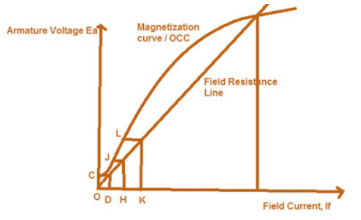
Fig 13 Shunt Generator
A small current will start flowing through the field circuit of DC Shunt Generator which in turn will produce magnetic flux and if the produced magnetic flux adds the residual magnetic flux, then net flux will increase and the generated voltage will increase corresponding to point J on the Magnetization curve as shown in figure below.
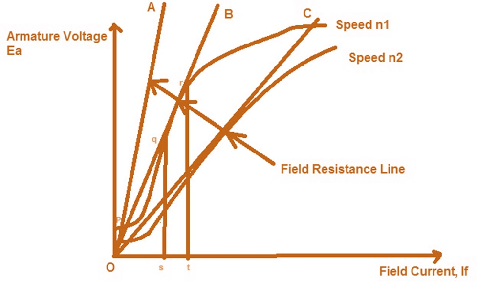
Fig 14 Voltage Build-Up
As the generated voltage has increased, therefore the field current will also increase to O-K corresponding to which the Generated Voltage across the Terminals of DC Shunt Generator will increase to point L. In the same manner the voltage will continue to build up till the point of intersection of Field Resistance Line and Magnetization curve / Open Circuit Characteristics of DC Shunt Generator. Beyond point of intersection of Field Resistance Line and Magnetization curve / Open Circuit Characteristics the voltage won’t build up as in that case the generated voltage will not be able to drive the required field current. Thus, the stable point at which the voltage will remain fix is the voltage corresponding to point of intersection of Field Resistance Line and Magnetization curve / Open Circuit Characteristics.
Key takeaway
The switch in the field circuit is supposed open and the armature of DC Shunt Generator is driven at rated speed. Due to the presence of small residual flux in the field poles, DC Shunt Generator will have a small voltage at its terminal.
If the field resistance is increased to OA, then Field Resistance line intersect the OCC curve at point p, and hence there will not be voltage build up beyond point p.
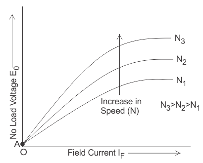
Fig 15 Critical Field Resistance
Now, if shunt field resistance is such that OB represents the Field resistance line then as clear from the figure above, the lone is intersecting the OCC curve at many points between q and r, therefore the field current will fluctuate between s and t and hence the voltage generated at the terminals of DC Shunt Generator will vary from qs to rt resulting in unstable condition. If we find the slope (tanƟ) of the Field Resistance Line then we will get Field Resistance value which is known as Critical Filed Resistance. Here Critical Field Resistance = tanƟ = qs/Os
As clear from the figure above, if the field resistance is more than the Critical Field Resistance then there will not be voltage build up in DC Shunt Generator. See in the figure OA is shunt field resistance which is more than Critical Field Resistance OB (check by slope, slope of OA is more than slope of OB), hence there is no voltage build up in DC Shunt Generator.
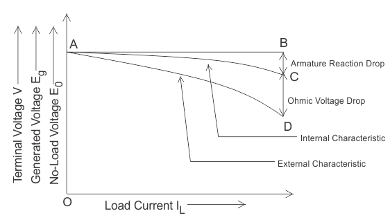
Fig 17 Field Resistance and Speed Relation
Suppose the field resistance is OC and DC Shunt Generator is running at a speed of n1 for which the stable point of its terminal voltage is C. Now the speed of DC Shunt Generator is reduced to n2 therefore the OCC curve will also move downward as shown in figure. It should be noted here that the same field resistance line OC is now tangent to the new OCC curve and therefore will create an unstable condition of operation of DC Shunt Generator. This speed n2 is hence called Critical Speed.
Key takeaway
If we find the slope (tanƟ) of the Field Resistance Line then we will get Field Resistance value which is known as Critical Filed Resistance. Here Critical Field Resistance = tanƟ = qs/Os
V-I characteristics of Separately excited
The curve which gives the relation between field current (If) and the generated voltage(E0) in the armature on no load is called magnetic or open circuit characteristic of a DC generator. The plot of this curve is practically same for all types of generators whether they are separately excited or self-excited. This curve is also known as no load saturation characteristic curve.
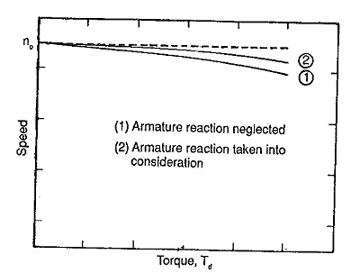
Fig 18 V-I Characteristics of Separately Excited DC Motor
Internal or Total Characteristic of Separately Excited DC Generator
The internal characteristic of the separately excited DC generator is obtained by subtracting the drops due to armature reaction from no load voltage. This curve of actually generated voltage (Eg) will be slightly dropping. Here, AC line in the diagram indicating the actually generated voltage (Eg) with respect to load current. This curve is also called total characteristic of separately excited DC generator.
External Characteristic of Separately Excited DC Generator
Terminal voltage(V) = Eg – Ia Ra.
This curve gives the relation between the terminal voltage (V) and load current. The external characteristic curve lies below the internal characteristic curve.
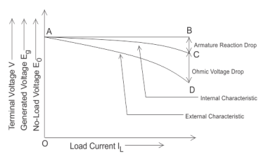
Fig 19 External Characteristic of Separately Excited DC Generator
The line AD in the diagram below is indicating the change in terminal voltage(V) with increasing load current. It can be seen from figure that when load current increases then the terminal voltage decreases slightly. This decrease in terminal voltage can be maintained easily by increasing the field current and thus increasing the generated voltage. Therefore, we can get constant terminal voltage.
Separately excited DC motor
The circuit equation of a Speed Torque Characteristic of Separately Excited DC Motor whose armature, having a total of Z conductors, is wound for P poles (the brushes divide the winding into A parallel paths), is
Va=E+IaRa
Where E is the back emf of the armature given by
E=
From above equations
N=
Torque developed will be
Td=
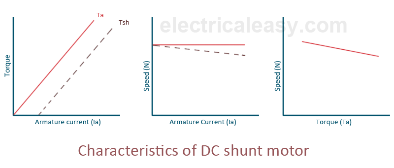
Fig 20 Torque-Speed Characteristics
The figure clearly shows a speed drop of 2 to 3% as the torque varies from no-load to full load.
DC Series Motor
Speed and Torque characteristics: As Ta α φ Ia and φ α Ia, but N αEb/ Ia. So, it can be easily concluded that speed and torque are inversely proportional. Hence when speed is high torque is low and vice versa. The curve is shown below.
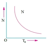
Fig21: Speed verses Torque characteristics
DC Shunt Motor
Speed and Torque Characteristics: From above to characteristics, curve for this shown below.
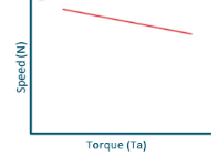
Fig22: Speed verses Torque characteristics
Key takeaway
Example
Que) A 250V shunt motor on no load runs at 900rpm and takes 4amperes, armature and shunt field resistances are 0.2 and 250 ohms respectively. Calculate the speed when loaded taking current of 50A. The armature reactions weaken the field by 3%?
Sol: Ish=250/250=1A
Ia1=4-1=3A
Ia2=50-1=49A
Eb1=250-3*0.4=248.8V
Eb2=250-49*0.2=240.2A


N2=898rpm
Que) The speed of a 37.3kW series motor working on 500V supply is 600 rpm at full load and 90% efficiency. If the load torque is made 250 N-m and a 5ohm resistance is connected in series with the machine, calculate the speed at which the machine will run. Assume armature and field resistance of 0.5ohm?
Sol: Load torque in first case T1=37300/2 (600/60) =593.65 N-m
Input current Ia1=37300/0.9*500=82.9A
T2=250 N-m. So, finding Ia2
For series motor T α φ Ia α Ia2
T1 α  and T2 α

 =82.9*
 =53.79A
Eb1=500-(82.9*0.5) =458.5V
Eb2=500-53.79(5+0.5) =204.11V


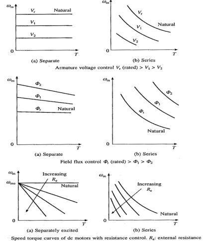
Armature control DC motor can be:
a) Armature Resistance Control Method
b) Shunted Armature Control Method
c) Armature Terminal Voltage Control
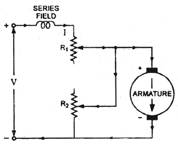
a) Armature or Rheostatic control: This is the most common method employed. In this the controlling resistance is connected directly in series with the supply of the motor. As resistance Ra is increased potential drop across armature decreases, and hence the speed too decreases. The figure is shown below.
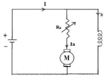
Fig23: Armature control
One more to control speed here is shunting the armature and a rheostat in series with the armature is involved in this method of speed control. The voltage applied to the armature varies by varying series rheostat R1. The exciting current can be varied by varying the armature shunting resistance R2. This method of speed control is not economical due to considerable power losses in speed controlling resistances.
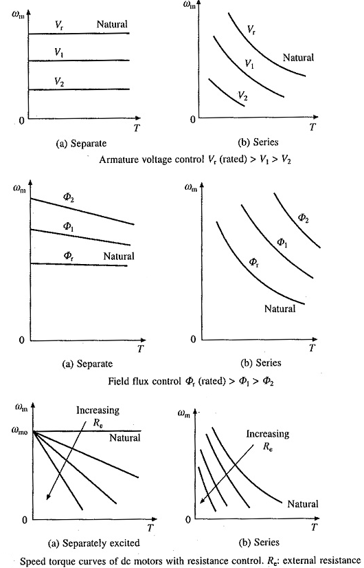
Fig24: Shunted armature speed control
b) Shunted Armature Control
The combination of a rheostat shunting the armature and a rheostat in series with the armature is involved in this method of speed control. The voltage applied to the armature is varied by varying series rheostat R1. The exciting current can be varied by varying the armature shunting resistance R2. This method of speed control is not economical due to considerable power losses in speed controlling resistances. Here speed control is obtained over wide range but below normal speed.
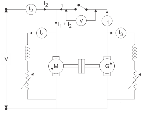
Fig 25 Shunted Armature Control
c)Terminal Voltage Control
The speed control of DC series motor can be accomplished by supplying the power to the motor from a separate variable voltage supply. This method involves high cost so it rarely used.
Key takeaway
Losses
1) Copper loss –
Armature Cu loss = Ia2 Ra
Field Cu loss:
a) For shunt = Ish2Rsh
b) For series = Ise2Rse
2) Magnetic loss
a) hysteresis loss: Wh B1.6max f
b) Eddy current loss: We B2max f2
Mechanical loss – They are basically the frictional losses at bearings and commutators.
The back-to-back testing is one of the methods for testing the efficiency of the DC machine. It is a full load test and requires two identical machines which are coupled together. In these two one machines is operated as generator to supply mechanical power to the motor and other is operated as motor to drive the generator. This test is also called as Hopkinson’s Test. As there is drop in the generator output voltage, we need an extra voltage source to supply the required input voltage to motor. The output power from the external supply is used to overcome the internal losses of the motor-generator set.
A motor and a generator, both identical, are coupled together. When the machine is started it is started as motor. The shunt field resistance of the machine is adjusted so that the motor can run at its rated speed.
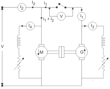
Fig26: Circuit for back-to-back test
The generator voltage is now made equal to the supply voltage by adjusting the shunt field resistance connected across the generator. This equality of these two voltages of generator and supply is indicated by the voltmeter as it gives a zero reading at this point connected across the switch. The machine can run at rated speed and at desired load by varying the field currents of the motor and the generator.
Calculation of Efficiency by Hopkinson’s Test
Let V= supply voltage of machine
Motor input= V(I1+I2)
I1 = The current from the generator
I2 = The current from the external source
And, Generator output = VI1……………… (1)
Let the efficiency of both the machines be 
The motor output will be =  x input=
  x V(I1+I2)
output of motor = Input to generator=  x V(I1+I2)
output of generator=  x input=
  x V(I1+I2)] =
 x V(I1+I2) …………. (2)
From (1) and (2)
VI1= x V(I1+I2)
I1= (I1+I2)
 =
= 
Armature copper loss in the motor =(I1+I2-I4)2Ra
Shunt field copper loss in the motor will be = VI4
Next, in case of generator armature copper loss in generator =(I1+I3)2Ra
Shunt field copper loss in the generator = VI3
Now, Power drawn from the external supply = VI2
Ra is the armature resistance of both motor and generator.
I4 is the shunt field current of the motor.
I3 is the shunt field current of the generator.
Therefore, the stray losses in both machines will be
W=VI2-(I1+I2-I4) Ra+VI4+(I1+I3)2Ra+VI3
If Stray losses are same for both the machines= W/2
Efficiency of Generator
WG=(I1+I3)2Ra+VI3+
Total losses in the generator,
Generator output = VI1
The generator efficiency is
 =
= =
= =
=
Efficiency of Motor
WM=(I1+I2-I4)2Ra+VI4+
Total losses in the motor,
Motor Input= V(I1+I2)
Then, efficiency of the motor,
 =
= =
= =
=
Advantages of Hopkinson’s Test
Disadvantages of Hopkinson’s Test
The demerits of this test are
Key takeaway
The generator efficiency is
 =
= =
= =
=
Then, efficiency of the motor,
 =
= =
= =
=
Example
Que) The Hopkin’s test on two similar shunt machines gave the following Full load data. Line voltage = 110 V; Line current = 48 A; Motor armature current = 230 A; Field currents are 3 A and 3.5 A; Armature resistance of each machine is 0.035 Ω; brush drop of 1V/brush; Calculate the efficiency of each machine.
Sol: Motor:
Armature copper loss = (230)2 x 0.035 = 1851.5 W
Brush contact loss = 230 X 2 = 460 W
Total armature copper loss = 1851.5 + 460 = 2312 W
Shunt field copper loss = 110 X 3 = 330 W
Total copper loss = 2312 + 330 = 2642 W
Generator:
Generator armature copper loss = (188.5)2 x 0.035 = 1244 W
Brush contact loss = 188.5 X 2 = 377 W
Total armature copper loss = 1244 + 377 = 1621 W.
Shunt field copper loss = 110 X 3.5 = 385 W
Therefore, total copper loss = 1621 + 385 = 2006 W
Total copper loss for set = 2642 + 2006 = 4648 W
Total input = 110 X 48 = 5280 W
Therefore, stray losses = 5280 – 4648 = 632 W
Stray losses/machine =632/2=316
Total losses = 2312 + 330 + 316 = 2.958 kW
Motor input = 110 X 233 = 25.630 kW.
Motor output = 22.672 kW
 =
= =
= =88.45%
Generator total losses = 1621 + 385 +316 = 2.322 kW
Output of generator = 110 X 185 = 20.350 kW
 =
= =
= =89.4%
Que) In a Hopkinson test on 250 V machine, the line current was 50 A and the motor current is 400 A not including the field currents of 6 and 5 A. the armature resistance of each machine was 0.015Ω. Calculate the efficiency of each machine.
Sol: Motor armature copper loss = (400)2 X 0.015 = 2400 W
Generator armature copper loss = (350)2 X 0.015 = 1838 W
Input power = 250 X 50 = 12500 W
Ws stray losses = 12500 – (2400 + 1838) = 8262 W;
Ws per machine = 8262/2=4130
Motor efficiency:
armature copper loss of motor = 2400 W;
Motor field copper loss = 250 X 5 = 1250 W
Total motor losses = 2400 + 1250 + 4130 = 7780 W
Motor input = 250 X 400 + 250 X 5 = 101250 W.
Therefore η = =
= = 92.3 %
Generator efficiency:
Generator armature copper loss = 1838 W
Generator field copper loss = 250 X 6 = 1500 W
Total losses of Generator = 1828 + 1500 + 4130 = 7468 W
Generator Output = 250 X 350 = 87500 W
Efficiency of Generator =  =
= =
= = 91.5%
References: