Unit - 1
Cartesian
Coordinate system
The various coordinate systems are:
(i) Cartesian or rectangular co-ordinate system
(ii) Cylindrical co-ordinate system
(iii) Spherical co-ordinate system
Representing a point in Rectangular Co-ordinate system
A point in rectangular co-ordinate system is located by three co-ordinates namely x,y and z co-ordinates. The point can be reached by moving from origin the distance of x in x-direction , distance of y in y-direction and finally distance of z in z direction.
Consider a point P having co-ordinates x1,y1 and z1 which can be positive or negative.
The point Q(3,-1,2) can be shown as
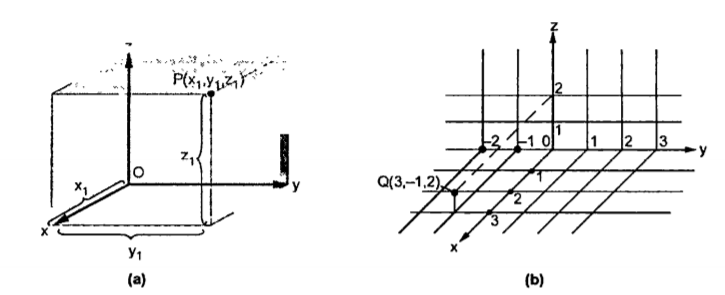
Figure 1. Rectangular co-ordinate system
Base vector :
The base vector are the unit vectors that are oriented along the directions of the co-ordinate axes of the given co-ordinate system. Thus for cartesian co-ordinate system the three base vectors are unit vectors oriented in x,y and z axis of the system. Therefore
  ,
, and
and  are the base vectors of the cartesian co-ordinate system.
Any point of the x-axis having (x1,0,0) can be represented by a vector joining origin to this point to this point and denoted as x1 .
.
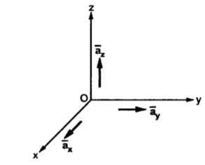
Figure 2. Base vector
Position and Distance vectors :
Consider a point P (x1, y1, z1) in cartesian co-ordinate system as shown in figure. Then the position vector of point P from the origin directed from origin to point P. This is called radius vector as shown in figure.
The three components of position vector oriented along the three co-ordinate axes with magnitudes x1, y1and z1. Thus, the position vector of point P can be represented as
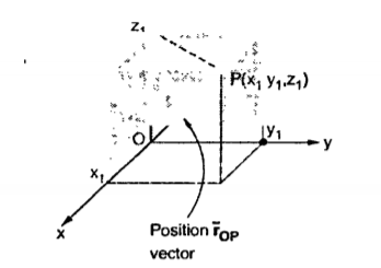
Figure. 3 Position vector
 OP= x1
  + y1
+ y1  + z1
+ z1 
The magnitude of this vector in terms of three mutually perpendicular components is given by
| OP|=
OP|= 2 + (y1) 2+ (z1) 2
Thus, if point P has co-ordinates (1,2,3) then its position vector is
 OP=1
OP=1  + 2
+ 2  + 3
+ 3 
And
 OP =
OP = (1) 2 + (2) 2 + (3) 2 =
  = 3.7416
Consider two points in a cartesian coordinate system P and Q with the co-ordinates (x1, y1, z1) and (x2, y2, z2) respectively. The individual position vectors of the points are
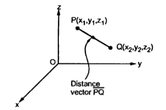
Figure 4. Cartesian coordinate system
 = x2
= x2  + y2
+ y2  + z2
+ z2 
Then the displacement from P to Q is represented by the distance vector  and is given by
 =
=  -
-  = [x2 -x1]
  + [ y2 -y1]
  + [z2 -z1]
This is called separation vector.
The magnitude of the vector is given by
| | = √ (x2 -x1) 2 + (y2 -y1) 2 +(z2 – z1) 2
This is called as distance formula.
The unit vector along the direction PQ is given by
 PQ= Unit vector along PQ =
  / |PQ|
Obtain the unit vector in the direction from the origin towards the point P (3, -3, -2)
Solution:
The origin O (0,0,0) while P (3, -3, -2) hence the distance vector  is
is
 = (3-0)
  + (-3-0)
  +(-2-0)
  = 3
= 3  -3
-3  -2
-2 
 =
=  (3) 2 + (-3) 2 + (-2) 2 = 4.6904
Hence the unit vector along the direction OP is
 OP=
OP=  / |
/ | | = 3
| = 3  -3
-3  -2
-2  / 4.6904 =
= 0.6396 -0.63963
  -0.4264
Differential Elements in Cartesian Co-ordinate System
Consider a point P (x, y, z) in the rectangular co-ordinate system. If we increase each co-ordinate by a differential amount a new point P’ will be obtained having co-ordinates (x+dx, y +dy, z+dz)
dx = differential length in x-direction
dy = differential length in y-direction
dz = differential length in z-direction
Hence differential vector length called elementary vector length
 = dx
= dx  -dy
-dy -dz
-dz .
.
P is the intersection of the three planes and P’ is the intersection of the new three planes which are displaced from original three planes. These six planes together define a differential volume which is a rectangular parallelepiped as shown in the figure.
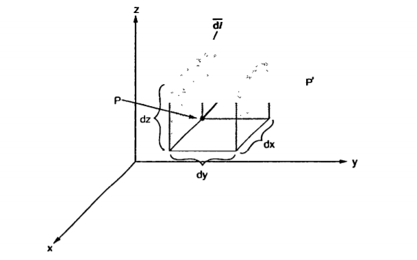
Figure 5. Cartesian coordinate system
 = dx
= dx  -dy
-dy -dz
-dz .
.
Hence the differential volume of the rectangular parallel piped is given by
dv = dx dydz
 is vector and dv is scalar.
The differential surface area is given by
 =
=  n
n
ds = Different surfaces area of the element.
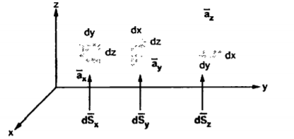
Figure 6. Differential vector system
d = Differential vector surface area normal to x direction dy dz
d = = Differential vector surface area normal to y direction dx dz
d = = Differential vector surface area normal to y direction dx dy
Given the three points in cartesian co-ordinate system as A (3, -2,1) B (-3, -3,5), C (2,6, -4)
Find
i) The vector from A to C
ii) The unit vector from B to A
iii) The distance from B to C
iv) The vector from A to the mid-point of the straight-line joining B to C.
The position vectors for the given points are:
 = 3
= 3 - 2
- 2 +
+ .
.
 = -3
= -3 - 3
- 3 +5
+5  .
.
 = 2
= 2 +6
+6 -4
-4 .
.
i) The vector from A to C is
 =
=  -
-  = [ 2-3]
  + [6– (-2)]
 + [-4-1]
  .
.
= -  + 8
+ 8 -5
-5  .
.
ii) For unit vector from B to A obtain the distance vector  first
first
 =
=  -
- 
= [ 3 – (-3)] + [ (-2) – (-3)]
  + [ -4-1]
= 6  +
+  -4
-4  .
.
| | =
| =  (6) 2 + (1) 2 + (-4)2 = 7.2801.
 BA =
BA =  / |
/ | | = 6
| = 6  +
+  -4
-4  ./ 7.2801
iii) For distance between B and C
 =
=  -
-  = [ 2 – (-3]
  + [6-(-3)]
  + [-4) – (-5)]
  = 5
= 5  + 9
+ 9  – 9
– 9 
Distance BC =  2 + (9) 2 + (-9) 2 = 13.6747
iv) Let B (x1, y1, z1) and C (x2, y2, z2) then the co-ordinates of the mid-point BC are (x1+x2/2, y1+y2/2, z1+z2/2)
Cylindrical co-ordinate system
The ranges of the variable are:
0 ≤ r ≤ ∞------------------(1)
0 ≤Ø≤ 2π------------------------------(2)
-∞≤z≤∞--------------------------------------------------(3)
The point P in cylindrical co-ordinate system has three co-ordinates r, Ø and z whose values lie in the ranges given by equations 1,2,3.
The point P(r,Ø1,z1) can be shown in figure (b)
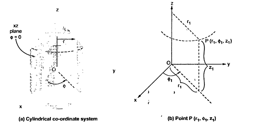
Figure.7 Cylindrical coordinate system
The point P can be defined as the intersection of three surfaces in cylindrical co-ordinate system. These three surfaces are,
r = Constant which is circular cylinder with z axis as its axis
Ø= Constant plane which is a vertical plane perpendicular to xy plane making angle Ø with respect to xz plane.
z= Constant plane is a plane parallel to xy plane.
These surfaces are shown in figure.
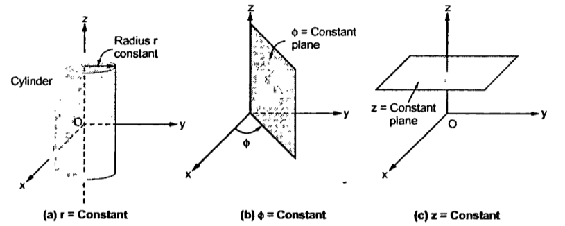
Figure.8 Surfaces of cylindrical coordinate system
The intersction of any two surfaces out of the above three surfaces is either a line or a circle and intersection of three surfaces define a point.
The intersection of z=constant and r=constant is a circle. The intersection of ɸ=constant and r=constant is a line. The point P which is intersection of all three surfaces is shown in the figure.
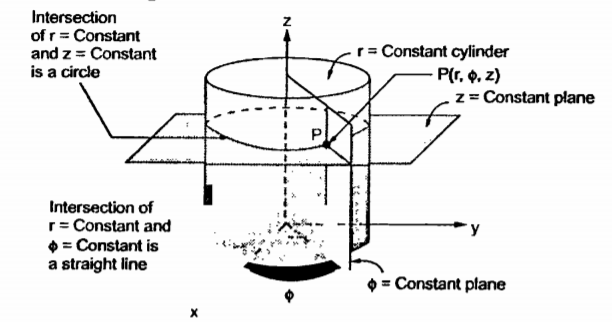
Figure.9 Intersection
Base vectors:
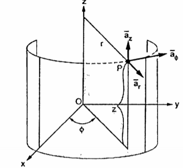
Figure. 10 Base vector
These are mutually perpendicular to each other. The  lies in a plane parallel to xy plane and perpendicular to the surface of the cylinder at a given point coming radially outwards. The vector
  lies also in a plane parallel to xy plane but it is tangent to the cylinder and pointing in the direction of increasing
  at the given point.
The unit vector  is parallel to z-axis and directed towards increasing z. Hence, vector of point P can be represented as
 = P r
= P r  + P ɸ
+ P ɸ + P z
+ P z 
Differential Elements in Cylindrical co-ordinate system
Consider o point P (r, ɸ, z) in a cylindrical co-ordinate system. Let each co-ordinate be increased by differential amount. The differential increments in r, ɸ, z is dr, dɸ and dz respectively.
There are two cylinders of radius r and r+dr. There are two radial planes at the angles ɸ and ɸ+dɸ. And there are two horizontal planes at the heights z+dz. All these surfaces enclose a small volume as shown in figure.
The different lengths in r and z are dz and dr respectively. In ɸ direction dɸ is the change in angle ɸ and is not the differential length. Due to this change dɸ there exists a differential arc length in ɸ direction. This differential length due to dɸ in ɸ direction is r dɸ as shown in figure.
Thus, the differential lengths are:
dr = Differential length in r direction.
r dɸ = Differential length in ɸ direction
dz = Differential length in z direction
Hence the differential vector length in cylindrical co-ordinate system is given by
 = dr
= dr  + r dɸ
 + dz
+ dz 
The magnitude of the differential length vector is given y
| (dr) 2 +( r d ɸ) 2 + (dz) 2
Hence the differential volume of the differential element is given by
dv = r drdɸdz
Spherical co-ordinate system:
The surfaces which are used to define the spherical co-ordinate system on the three cartesian axes are:
Thus the three co-ordinates of a point P in the spherical co-ordinate system are (r,Ѳ,Ø). These surfaces are shown in figure
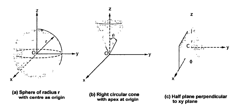
Figure. 11 Spherical coordinate system.
The ranges of the variables are,


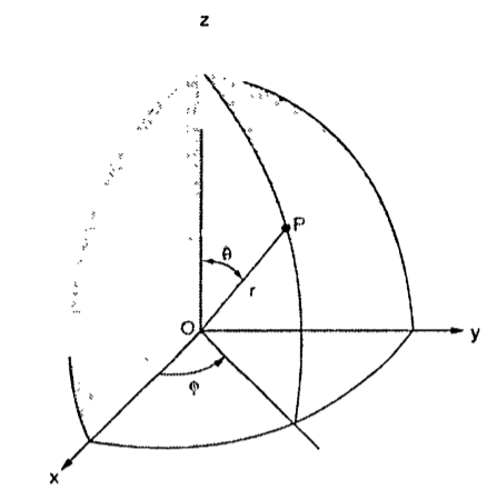
Figure. 12 Points in the spherical coordinate system
The point P(r,Ѳ,Ø) can be represented in the spherical co-ordinate system as shown in figure. The angles Ѳ and Ø are measured in radians. The point P can be defined as the intersection of three surfaces in spherical co-ordinate system. These three surfaces are:
r = Constant which is a sphere with cenre as origin
Ɵ = Constant which is right circular cone with apex as origin and axis a z axis
ɸ= Constant is a plane perpendicular to xy plane.
Base Vector:
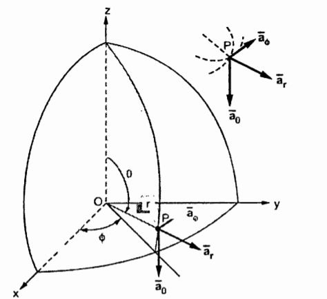
Figure.13 Base vector
There are three-unit vectors in r, Ɵ and ɸ directions denoted as  ,
,  and
and  . These unit vectors are mutually perpendicular to each other as shown in figure. The unit vector
  is directed from the centre of the sphere that is the origin to the given point P. It is radially outward normal to the sphere. It lies in the cone Ɵ = constant and plane ɸ= constant.
The unit vector  is tangent to the sphere and oriented in the direction of increasing Ɵ. It is normal to the conical surface.
The third unit vector  is tangent to the sphere and also tangent to the conical surface. It is oriented in the direction of increasing ɸ. It is same as defined in the cylindrical co-ordinate system.
Hence, vector P is
Differential elements in Spherical co-ordinate system.
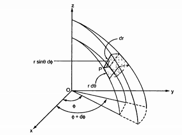
Figure.14 Spherical coordinate system
Consider a point P (r, Ɵ, ɸ) in spherical co-ordinate system. Let each co-ordinate be increased by the differential amount. The differential increments in r, Ɵ, ɸ are dr, dƟ and dɸ.
Now there are two spheres of radius r and r+dr. There are two cones with half angles Ɵ and Ɵ+dƟ. There are two planes at the angles ɸ+dɸ measured from xz plane. All these surfaces enclose a small volume as shown in figure.
dr= Differential length in r direction
r d Ɵ = Differential length in Ɵ direction
r sin Ɵdɸ = Differential length in ɸ direction.
Hence the differential vector length in spherical coordinate system is
The magnitude of the differential length vector is
| | = √ (dr) 2 + (r d
 2 + (r sin
  dɸ) 2
dɸ) 2
Hence differential volume is given by
dv = r 2 sin  dr d
dr d d
d 
Key Takeaways:
A Cartesian coordinate system is a coordinate system that specifies each point uniquely in a plane by a set of numerical coordinates, which are the signed distances to the point from two fixed perpendicular oriented lines, measured in the same unit of length.
If at every point of a region, there is corresponding value of some physical function, the region is called a field. Mathematically, a field is a function which describes a physical quantity at all points in space. Field is classified as scalar or vector.
i) Scalar field: If the value of the physical function at every point is scalar quantity, then the field is scalar field for example temperature of atmosphere density of the nonhomogeneous body and electric potential scalar field.
ii) Vector field: If the value of the physical function at every point is vector quantity, the field is vector field for example the wind velocity of atmosphere, gravitational force and electric field intensity are vector fields.
Line Integrals
It is defined as any integral which is to be determined along a curve. Line integral can be defined in terms of limits of sum as are the integrals of ordinary calculus.


Above mentioned are some examples of line integrals calculated from point a to point b. In first case each element of length dl on the curve is multiplied by the local value A scalarly and then these products are summed to get the value of the integral.
Line integral in terms of cartesian coordinate can be represented as

Surface Integrals
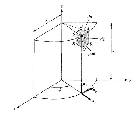
Fig 15 A two-sided surface
Differential Distances: 

Differential Surfaces:


Different Volume:

Volume Integrals
If a closed surface in space enclosing a volume V is considered then the integrals


Are the examples of volume integrals. Since volume is a three-dimensional quantity and hence three integrals.
Key takeaway
It states that force between two-point charges Q1 and Q2

Figure.16 Two point charge
Consider two point charges Q1 and Q2 as shown in the figure seperated by distance R. The charge Q1 exerts a force on Q2 while Q2 also exerts a force on Q1. The force acts along the line joining Q1 and Q2. The force exerted between them is repulsive if the chrages are of same polarity while it is attractive if the charges are of different polarity.
Mathematically the force F between the charges can be expressed as,
F α Q1Q2/ R 2
Q1Q2------ Product of two charges
R ------- Distance between the two charges
The law also states that the force depends on the medium in which the point charges are located. The effect of medium is introduced in the equation of force as a constant of proportionality denoted as k.
F = k. Q1 Q2/ R2
The constant of proportionality takes into account the effect of medium.
Therefore,
k = 1/ 4 π 
 = Permittivity of medium in which charges are located. The units of
  are farads/metre(F/m)
In general,  is expressed as,
 =
= 
 Permittivity of free space or vacuum
 = Relative permittivity or dielectric constant of the medium with respect to free space.
 Absolute permittivity
For free space or vacuum the relative permittivity  hence
hence
 =
= 
F = 1/ 4 π  . Q1Q2/ R2
The value of permittivity of free space  is
is
 1/ 36 π x 10 -9 = 8.854 x 10 -12 F/m
k = 1/ 4π  = 1/ 4π x 8.854 x 10 -12 = 8.98 x 10 9 = 9 x 10 9 m/F
Hence the Coulombs law can be expressed as,
F = Q1 Q2 / 4π  R 2
R 2
This the force between the two-point charges located in free space or vacuum.
Problem:
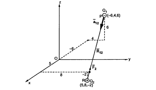
A charge Q1=-20µC is located at P (-6,4,6) and a charge Q2=50µC is located at R (5,8, -2) in a free space. Find the force exerted on Q2 by Q1 in vector form. The distances given are in meters.
From the co-ordinates of P and R the respective position vectors are:
 = -6
= -6  + 4
+ 4  + 6
+ 6 
and
 = 5
= 5  + 8
+ 8  -2
-2 
The force on Q2 is given by
 = Q1 Q2 / 4 π
  R212.
R212.
 =
=  =
=  -
-  = [ 5 – (-6)]
  + (8-4)
  + [-2-(-6)
  ]
]
= 11  + 4
+ 4  - 8
- 8 
|R12| =  (11) 2 + (4) 2 +(-8) 2 = 14.1774
 =
=  / |
/ | | = 11
  + 4
+ 4  -8
-8  / 14.1774
 = -20 x 10 -6 x 50 x 10 -6 / 4 π x 8.854 x 10 -12 x (14.1774) 2 [
= -0.0447 [ 0.7758  + 0.2821
  - 0.5642
  ]
]
= -0.0346  - 0.01261
  + 0.02522
  N
N
This is the required force exerted on Q2 by Q1
The magnitude of the force is
| =
=  (0.0346) 2 + (0.01261) 2 + (-0.02522) 2 = 44.634mN
Definition:
The electric flux passing through any closed surface is equal to the total charge enclosed by that surface.
The total charge enclosed by the irregular closed surface is Q coulombs. Hence the total flux has to pass through the closed surface is Q. Consider a small differential surface dS at point P. As the surface is irregular the direction of D as well as its magnitude is going from point to point on the surface. The surface dS under consideration can be represented in vector form.
d  = d S
= d S 
where  = Normal to the surface d at point P
The flux density at point P is D and its direction is such that it makes an angle Ѳ with the normal direction at point P.
The flux d passing through the surface dS is the product of the component normal to dS and d
 .
.
Mathematically thus can be represented as,
d  = Dn dS
Dn = component of  in the direction of normal to the surface dS
From the figure we can write
Dn = | | cos
| cos 
d  = |
= | | cos
| cos  dS
dS
From the definition of the dot product
 .
.  = |A| |B| cos ƟAB
| | cos
| cos  dS =
dS =  d
d 
This is the flux passing through incremental surface area dS. Hence the total flux passing through the entire closed surface is to be obtained by finding the surface integration of the equation
 =
=  =
= 
 sign indicates the integration over the closed surface called closed surface integral.
Such a closed surface over which the integration in eq (6) is carried out is called Gaussian surface.
Total charge enclosed by the surface is given by
 =
=  = Q = Charge enclosed.
Consider a point charge Q1 as shown in figure:
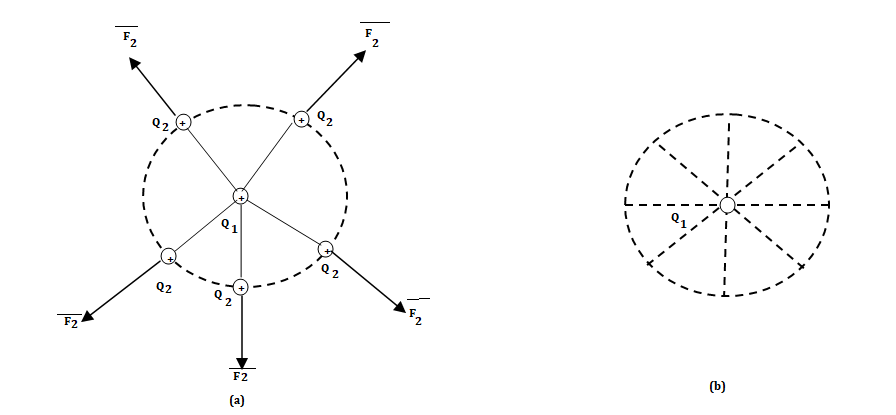
Fig 17 Electric Field Intensity
If any other similar charge Q2 is brought near it Q2 experiences a force. Infact if Q2 is moved around Q1 still Q2 experiences a force as shown in figure.
Thus, there exists a region around a charge in which it exerts force on any other charge. This region where a particular charge exerts a force on any other charge located in that region called electric field of that charge. The electric field of Q1 is shown in figure (b).
The force experienced by the charge Q2 due to Q1 is given by Coulombs law as,

Thus, force per unit charge can be written as:

This force exerted per unit charge is called electric field intensity or electric field strength. It is a vector quantity and is directed along a segment from the charge Q1 to the position of any other charge.
It is denoted as 
Another definition of electric field is the force experienced by a unit positive test charge that is Q2 = 1C.
Consider a charge Q1 as shown in figure below. The unit positive charge Q2=1C is placed at distance R from Q1. Then the force acting on Q2 due to Q1 is along the unit vector  . As the charge Q2 is unit charge the force exerted on Q2 is nothing but electric field intensity
  of Q1. Then the force acting on Q2 due to Q1 is along the unit vector
  . As the charge Q2 is unit charge the force exerted onQ2 is nothing but electric field intensity
  of Q1 at a point where unit charge is placed.
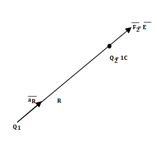
Fig 18 Concept of electric field intensity

If a charge Q1 is located at the centre of the spherical coordinate system then unit vector  in equation (3) becomes the radial unit vector
  coming radially outwards from Q1 and the distance R is the radius of the sphere r.
Key takeaway

The region in which the influence of an electric charge can be felt is known as electric field. The force experienced by a unit positive charge at a point is called is electric field strength.
E= F/q N/C or V/m
Electric flux density is defined as the amount of flux passes through unit surface area in the space at right angle to the direction of electric field.
E = 
Q: charge
r: distance between the object and field
The surface integral of electrostatic field produced by any source over any closed surface S enclosing a volume V in vacuum i.e., total electric flux over the closed surface S in vacuum is X the total charge (
 ) contained inside S i.e.

The charge inside S maybe point charges as well as continuous charge distributions.
The surface chosen to calculate the surface integral is called Gaussian surface.
Proof: -
Suppose an isolated positive point charge q is situated at the centre of the sphere of radius r,
According to coulomb’s law, electric field intensity at every point on the surface of the sphere is

Where is unit vector directed from +q to the surface element
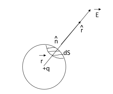
Fig 19 Charge q at centre of Sphere
Consider small area element ds represented by the vector where is unit vector  along out drawn normal to the area element


Integrating over the closed surface area of sphere we get


Which proves gauss theorem.
If there are two-point charges  lying inside the surface, each will contribute the electric flux independent of the others.
(Superposition principle)


 sum of all the charges inside the closed surface if the medium surrounding the charge has a dielectric constant K, then


If there is no net charge within the closed surface that is
Key takeaway
Integrating over the closed surface area of sphere we get

By doing the indicated operation e obtained r, the volume charge density. This is the differential statement of Maxwell’s equation No.1.

The equation states that the divergence of the electric flux density at a point is equal to the charge per unit volume at that point. The dot product, as always, produces a scalar result. In this case, the result is r, the number of coulombs of charge per cubic meter.
It is instructive at this point to continue using the integral and differential equations just developed for Maxwell’s Equation No.1 in order to illustrate a vector identity called, "Gauss’ Divergence Theorem". This identity equates a vector surface integral to a vector volume integral.


By substituting  for r in the integral equation we obtain;

This is a typical illustration of Gauss’ divergence theorem, using vector D as the example. The point here is that any time we have a vector surface integral of this type we can substitute the volume integral. If we have a vector volume integral of the above type, we can substitute the surface integral. The integral of the divergence of a vector summed throughout the volume is equal to the integral of the product of the vector times its effective area summed over the area. This is analogous to stating that the volume of a ball is contained within its surface area. The circle on the integral sign indicates that the integral is taken over a continuous area.
Key takeaway
vector surface integral to a vector volume integral.


Consider that in space let W be the unique function of x, y, z co-ordinates in the cartesian system. This is scalar function denoted as W (x, y, z). Consider the vector operator in cartesian system denoted as  called del. It is defined as


The Gradient of a scalar W in various co-ordinate systems are given by,
S. No | Co-ordinate System | Grad W = |
1. | Cartesian |
|
2. | Cylindrical |
|
3. | Spherical |
|
Properties:
The various properties of a gradient of a scalar field W are:


U is another scalar function then,


Problem:
A scalar field is given by


Find its gradient at P (0,1,1) for Cartesian, P ( for cylindrical and P
 for the spherical.


 the
the  +9.0689


 At
At  the
the 


For energy density u and power flux S in EM (electromagnetic) fields is given by

As developed in detail here, definitions for energy transfer based on the use of EM potentials alone is shown to yield results more in keeping with intuition for conundrums such as the above, and in the process provide additional insight into the significance of the potentials (even in classical theory) that extend beyond simply that of constituting a placeholder for EM fields. For Maxwell fields the standard expression involving energy density and power flux
 (2)
(2)


 (3)
(3)
From (3) we find that this alternative form for the power flux S addresses, and provides alternative interpretations for, the conundrums referred to above in that (a) by virtue of the time derivatives no energy flow is attributed to static superposed electric and magnetic fields in free space, and (b) given that S j detailed calculation shows that energy can be seen to flow down the wire during the charging of a capacitor. Therefore, at least for this pair of problems, the definition of S given by (3) appears more aligned with our intuition relative to the physical processes involved.
Unfortunately, in the absence of a well-structured theoretical guideline, selection of the above and similar modifications, typically involving mixed field and potential terms, remains an ad hoc procedure at best. In the next Section we consider a universally applicable, systematic treatment based on the use of EM potentials alone.
Key takeaway
For energy density u and power flux S in EM (electromagnetic) fields is given by

 .
.  =
= 
 = flux density
 Volume charge density.
For a homogeneous isotropic and linear medium, flux density and the electric field are directly proportional. Thus,
 =
=  .
. 
 .
.  .
.  =
= 
From the gradient relationship
E = -  . V
. V
 .
.  (-
(-  . V) =
 (
(  .
.  V) =
V) = 
 .
.  V) =-
V) =-  /
/ 
Now  .
.  operation is called ‘del squared’ operation denoted as
  2.
2.
 2. V = -
  /
/ 
This equation is called as Poisson’s Equation
Laplace equation
If in a certain region volume charge density is zero (  which is true for dielectric medium then the Poisson’s equation takes the form,
 2. V =0.
This equation is called Laplace’s equation.
Application of Laplace and Poisson’s Equations
Using Laplace or Poisson’s equation we obtain:
Solution to simple cases
The procedure to solve a problem involving Laplace’s equation is:
Step 1: Solve the Laplace equation using the method of integration. Assume constants of integration.
Step2. Determine the constants by applying the boundary conditions given or known for the region. The solution obtained in step1 with constants obtained using boundary conditions is a unique solution.
Step 3: Then  can be obtained for the potential field V obtained using gradient operation -
  V.
V.
Step 4. For homogeneous medium  can be obtained as
  .
.
Step 5: At the surface  = DN hence
 is known. The normal component DN to the surface is known. Hence the charged induced on the conductor surface can be obtained as
Q = -  dS
dS
Step 6: Once the charged induced Q is known and potential V is known then the capacitance C of the system can be obtained.
If  0 then the same procedure can be obtained to solve Poisson’s equation.
Key Takeaway:
This is useful approach for calculation of electric potentials.
Gauss’s Law is useful to obtain  in case of complex problems. I magnetostatics complex problems can be solved using Ampere’s Law.
It states that
The line integral of magnetic field intensity  around closed path is exactly equal to direct current enclosed by that path.
The mathematical representation of Ampere’s circuital law is
 .
.  = I -------------------------------------(1)
This law is useful to determine  when current distribution is symmetrical.
Proof:
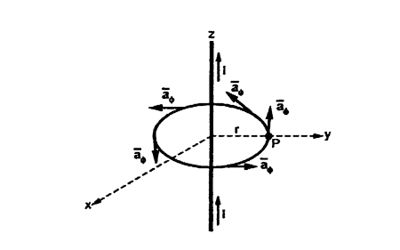
Figure.20 Current carrying conductor
Consider a long straight conductor carrying direct current I placed along z axis as shown in figure. Consider a closed circular path of radius r which encloses the straight conductor carrying direct current I. The point P is at perpendicular distance r from the conductor.
Consider  at point P which is direction
  direction tangential to circular path at point P.
Therefore,
 = r dɸ
While  obtained at point P, from Biot-Savart law due to infinitely long conductor is,
 = 1/ 2 π r.
 ɸ. r dɸ.
 ɸ
ɸ
= 1/ 2  r. dɸ = 1/ 2 π. dɸ
Integrating  .
.  over the entire closed path
 .
.  =
=  dɸ = 1/ 2 π [ɸ] 02π= I. 2 π/ 2 π
This proves that the integral  .
.  along closed path gives the direct current enclosed by that closed path.
Steps to Apply Amper’s Circuital Law:
Step1: Consider a closed path preferably symmetrical such that it encloses the direct current I once. This is Amperian path.
Step2: Consider differential length depending upon the co-ordinate system used.
Step3: Identify the symmetry and find in which direction  exists according to co-ordinate system used.
Step 4: Find  .
.  . Make sure that
  and
and  are in the same direction.
Step 5: Find the integral of  .
.  around the closed path. And equate it to current I enclosed by the path.
To apply Ampere’s circuital law the following conditions must be satisfied,


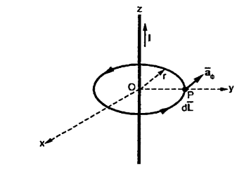
Figure.21 Field intensity of straight conductors
Consider an infinitely long straight conductor which is placed along z-axis carrying direct current I as shown in figure. Consider the Amperian closed path enclosing the conductor as shown in figure. Consider point P on the closed path at which  is obtained. The radius of the path is r from the conductor. The magnitude of
  depends on r and the direction is always tangential to the closed path. So,
  has only component in
  direction say H
  .
.
Consider elementary length  at point P in cylindrical co-ordinates it is r d
 in
in  .
.
 = Hɸ
= Hɸ ɸ and
ɸ and  = r dɸ.
 ɸ
ɸ
 .
.  = Hɸ
= Hɸ ɸ. r dɸ.
 ɸ = Hɸ r dɸ
According to Ampere’s circuit law,
 = I
= I
 ɸ. r. dɸ = I
Hɸ. r  . dɸ = I
Hɸ. r [2π] =I
Hɸ = 1/ 2π r
Hence  at point P is given by
 = Hɸ.
= Hɸ.  ɸ = 1/ 2 π r.
 ɸ
ɸ
Key Takeaways:
This law states that the integral of magnetic field density (B) along an imaginary closed path is equal to the product of current enclosed by the path and permeability of the medium.
It is the process of multiplication cross or vector product. If  is a vector function and is multiplied by another vector
From equation (1) and (2)


We have,
 ] (3)
] (3)
Putting this in determinant we have

This is called the curl of vector function  . Thus, mathematically curl of a vector function is defined as the cross product of deal and the given vector function.
The coal is defined as the line integral of the tangential component of the vector around the area per unit area.
Let us take an example of a curl which makes its significance clear is the vector velocity associated with the rigid rotation of a body. Let to body have an angular velocity w about the z-axis. Then the linear velocity at point (x, y, z) is given by 
 , we compete the curl and find at once that it is along the z direction, has a constant value independent of position and is magnitude 2w. Thus, it is twice the angular velocity of vector of rotating motion.
It is seen from (3) that curl A is a vector whose x, y, z components are
 4 (a)
4 (a)
 4 (b)
4 (b)
 4 (c)
4 (c)
A vector whose curl is zero is called irrational vector.
Key takeaway
 ]
]
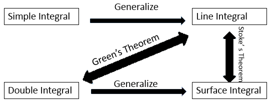
The stokes theorem relates the line integral to a surface integral. It states that the line integral of  around a closed path L is equal to the integral of curl
  over the open surface S enclosed by the closed path L.
Mathematically it is expressed as,
 . d
. d =
=  x
x  . d
. d
Where dL = Perimeter of total surface S
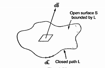
Figure.22 Line Integral.
Key Takeaways:
Stoke’s theorem is applicable only when  and
and  x
x  are continuous on the surface S.
 gives the flux flowing across surface S. Then mathematically divergence is defined as the net outward flow of the flux per unit volume over a closed incremental surface. It is denoted as div
  given by
 (1)
(1)
Where

Symbolically it is denoted as,

Where 
But 


This is divergence of  in Cartesian system.
Similarly, divergence in other co-ordinate systems are,


Physically divergence at a point indicate how much that vector field diverges from that point.
Consider a sloenoid that is the elctromagnet obtained by winding a coil around the core. When current passes through it flux produced around it. Such a flux completes a closed path through the solenoid hence solenoid field does not diverge. Therefore the vector field having its divergence zero is called solenoidal field.
 for
for  to be solenoidal.
Let us consider the magnetic field is due to electromagnet that is a coil of several no. turns.
This coil or inductor is carrying current I when it is connected across a battery or voltage source through a switch.
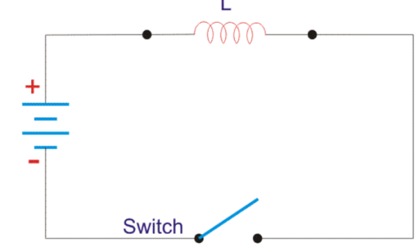
Figure.23 Inductor circuit
Suppose battery voltage is V volts, value of inductor is L Henry, and current I will flow at steady state.
When the switch is ON, a current will flow from zero to its steady value. But due to self- induction an induced voltage appears which is
E = -L dI/dt ---------------------------------------------------------------------(1)
Here E always in the opposite direction of the rate of change of current.
The energy or work done due to this current passing through this inductor is U. As, the current starts from its zero value and flows against the induced emf E, the energy will grow up gradually from zero value to U.
dU = W. dt, where W is the small power and W = – E.I
So, the energy stored in the inductor is given by
dU = W. dt = -E. I dt = L dI/dt. I dt = LIdI
Now integrate the energy from 0 to its final value.
U =  =
=  dI = ½ LI 2
Again
L =  o N 2 A /l
where N is the number of turns of the coil,
A is the effective cross-sectional area of the coil and l is the effective length of the coil.
Again,
I = H.l/N
Where, H is the magnetizing force, N is the number of turns of the coil and l is the effective length of the coil.
I = B.l/ 
Now putting expression of L and I in equation of U, we get new expression i.e.
U = μoN2 A /l. B.L/ μo N / 2 = B 2 Al/ 2 μo
Key Takeaways:
The energy stored in a magnetic field is equal to the work needed to produce a current through the inductor.
References:


