Unit - 2
Inductance of a Conductor due to Internal Flux
Recall a protracted, straight conductor with radius r meters and wearing a contemporary i amperes as shown inside the fig. (a).
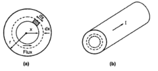
The magnetic discipline could be hooked up because of this present day. The magnetic flux lines will exchange inside the conductors that allows you to make a contribution to brought about voltage and as a result inductance.
The magnetic flux traces exist outside the conductor additionally. We may additionally assume that the return route for the modern in this conductor is a way away and the magnetic field of the conductor is not affected.
The cost of inductance due to internal flux is given via the ratio of flux linkages to modern-day by means of thinking of the reality that each line of internal flux links most effective a fragment of total cutting-edge.
The exact fee of inductance of transmission line is received through considering the flux internal each conductor in addition to outside flux. The traces of flux are concentric with the conductor. The mmf in ampere turns around any closed path is equal to the modern-day in amperes enclosed through the course. Therefore we've

In which H is magnetic discipline depth in at a point in x meters. Allow the magnetic area intensity at a factor x meter from the centre of the conductor be Hx. That is regular in any respect factors as field is symmetrical. Accordingly, integration of ds around the closed circular course is 2πx.

As Hx is constant
Because the current density is uniform


Substituting this value of ix in expression for hx

If μ = μo μr, then flux density on the given point is given by using,

 μr = 1 for the non-magnetic material

For the element having thickness dx, the flux could be made from and the cross-sectional place of the element normal to the flux strains. This area is dx instances axial period. If the axial length considered is 1m then the flux in line per meter is,

This flux hyperlinks with contemporary ix. For this reason, flux linkage in step with meter duration of conductor is given through

To locate internal flux or the total flux linkage inside the conductor we must convey the combination from the centre of conductor to its outside edge.


But μo = permeability of free area = 4π x 10-7 h/m


As a result, we've received inductance in step with unit period of a round conductor due to flux in the conductor. Inductance in step with unit period is referred as clearly inductance for comfort and simplicity.
Fig indicates two factors p1 and p2 at distances d1 and d2 from a conductor which incorporates a modern-day of i amperes. As the conductor is a long way eliminated from the return present day path, the magnetic area external to the conductor is concentric circles across the conductor and consequently all of the flux among p1 and p2 lines in the concentric cylindrical surfaces passing via p1 and p2.
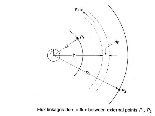
Magnetic flux intensity at a distance Y from conductor is

The flux dφ contained within the tubular element of thickness dy is
 length of conductive
The flux dφ being outside to the conductor hyperlinks all the modern within the conductor which collectively with the go back conductor at infinity bureaucracy a single return, such that its flux linkages are given by

Flux linkages of an isolated modern carrying conductor
Consequently, the whole flux linkages of the conductor because of flux among factors p1 and p2 is

Flux linkages of an isolated present day sporting conductor
Wherein in stands for natural logarithm.
Since 

Flux linkages of an isolated current carrying conductor
The inductance of the conductor contributed by using the flux included between points p1 and p2 is then

Considering single phase line consisting of conductors (phase and neutral) a and b of identical radius r. They're located at a distance d meters. The cross sections of conductors are proven in the diagram below.
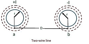
Let the current go with the flow in the conductors are opposite in direction in order that one will become return path for the alternative.
The flux linkages of conductor ‘a’ is given through the formulation

Inductance-of-two-wire here,
Ia = +i
Ib = -i
Daa = r’
Dab = d
Substituting those values in above equation


Similarly, the flux linkages with the conductor ‘b’ is

Flux linkages inductance of the conductor ‘a’

Similarly, the inductance of conductor ‘b’

Inductance per conductor

Inductance of both the conductors is given via the formula,
Loop inductance 

The inductance of a man or woman conductor is one-half of the whole inductance of a two-twire line.
Consider a composite conductor that is made from two or greater strands that are in parallel. For simplicity let us anticipate that everyone the strands are identical and proportion the modern equally. The sum of the currents in all of the conductors is zero. This kind of organization of conductors is shown inside fig.
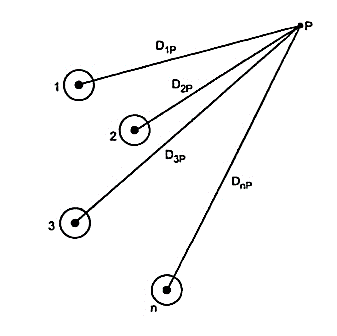
The conductors 1, 2, three, ... N convey the currents, N carry the currents i1, i2, i3... In. Permit the distances of the conductors from a factor p be d1p, d2p, d3p ... Dnp respectively. Let ψ1p1 be flux linkages of conductor because of its very own modern-day i1 due to inner and outside flux. The flux past factor p is excluded.

Now ψ1p2 is the flux linkages of conductor 1 due to current is equal to flux produced by I2 between the point P and conductor 1. Again, flux beyond P is neglected

Similarly, the flux linkages ψ1p with conductor 1 due to all of the conductors in the institution but the flux beyond point p is overlooked.

By way of increasing the logarithmic phrases and rearranging the phrases

The sum of all currents is zero.

Substituting this price in above equation
If factor p is at countless distance so that ln (d1p/dnp) ln (d2p/dnp) and so on will technique to zero (due to the fact that ln 1 = zero) then we have,

If  then
then

All of the flux linkages of conductor 1 are protected within the above derivation. The above expression is legitimate handiest best if sum of the currents is zero.
Inductance of composite conductor strains – we're now geared up to examine the inductance of transmission lines composed of composite conductors. Destiny 2.6 indicates any such single-phase line comprising composite conductors a and b with a having n parallel filaments and b having m’ parallel filaments.
Though the inductance of each filament will be incredibly unique (their resistances can be same if conductor diameters are chosen to be uniform), it is adequately correct to count on that the current is equally divided among the filaments of each composite conductor. Accordingly, every filament of a is taken to hold a modern i/n, whilst each filament of conductor b consists of the go back contemporary of — i/m’.
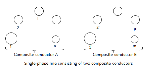
We obtain a flux linkage is,


The inductance of filament ‘I’ is then,

The average inductance of the filaments of composite conductor a is + l2 + l3 ±…+4,

Considering conductor, a is composed of n filaments electrically in parallel, its inductance is

The use of the expression for filament inductance from eq., we acquire

The numerator of the argument of the logarithm in eq is the m′nth root of the m′n phrases, which might be the goods of all feasible mutual distances from the n filaments of conductor a to m’ filaments of conductor b. It is referred to as mutual geometric mean distance (mutual gmd) between conductors a and b and is abbreviated as dm. Similarly, the denominator of the argument of the logarithm in eq. Is the n2th root of n2 product terms (n sets of n product phrases every). Each set of n product time period relates to a filament and consists of r′(dii) for that filament and (n-1) distances from that filament to each other filament in conductor a. The denominator is described because the self-geometric mean distance (self gmd) of conductor a, and is abbreviated as dsa. Once in a while, self-amp is likewise called geometric mean radius (gmr).
In phrases of the above symbols, we can write as in eq.


Note the similarity of the above relation with eq., which offers the inductance of one conductor of a unmarried-segment line for the special case of solid, spherical conductors. In eq. r’1 is the self gmd of an unmarried conductor and d is the mutual gmd of two unmarried conductors.
The inductance of the composite conductor b is decided in a comparable way, and the overall inductance of the road is

GMD stands for geometrical mean distance.
This concept could be very beneficial in electricity machine for the calculation of inductance and capacitance of transmission line.
Essentially, as we know that geometrical imply of n numbers a1, a2, a3…., anis
(a1a2a3a4…. An)1/n
The equal idea is likewise used for the calculation of gmd and gmr. In gmd we take the geometrical suggest of distances between the strands of transmission lines whilst in gmr, geometrical mean of distances between the stands of a single composite conductor are calculated.
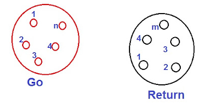
Let us assume composite conductors used in transmission line as proven in parent below.
As shown within the parent above, one conductor is cross and any other is return for present day for unmarried section line. The cutting-edge is believed to be similarly divided amongst all of the strands of a conductor.
Therefore,
Cutting-edge carried by way of each strand in cross conductor = i/n
Present day carried via every strand in go back conductor = -i/m
Right here i is the entire current carried through each conductor.
Now, we will calculate the gmd and gmr for the configuration of the conductors proven in parent above.
For buying the gmd, first we need to calculate the gap among the strands of move and go back conductors.
Let,
D11 = distance between the 1ststrand of cross and return conductor
D12 = distance among the 1ststrand of cross and second strand of return conductor
D21 = distance among the 2nd strand of move and 1st strand of return conductor
Dmn = distance among the mth strand of cross and nth strand of return conductor
Thus, the Geometrical mean of above distances i.e., GMD,

Geometrical imply radius of a solid conductor or a strand of radius r is described because the factious radius r’ having no inner flux linkage however having the same inductance because the original conductor of radius r.
R ‘= 0.7788r
The primary definition for transposition of transmission line is to rotate the conductors which bring about the conductor or a section being moved to subsequent physical location in a regular series. In electric strength transmission traces, the conductor arranges unequal space.
So, the voltage drops aren't identical as one location to any other. To do away with this effect can actually do via interchange the conductor role that's called transposition. Whilst the transmission line is more than 100 km lengthy, then, as in step with electrical requirements three levels needed to be transposed.
The transposition arrangement is plenty important which there may be a capacitance between the energy conductor. When the hig
Voltage carried out capacitance created among the conductors and conductor and ground.
Functions of transposition of transmission line
Transposition of transmission line are used to transpose the phase conductors in 3 sections in this sort of manner that each segment by means of rotation occupies every of the 3 phase positions in a circuit. In some other transposition association referred to as ‘on span transposition’.
The transposition power line arrangement is likewise which executed close to a high anxiety tower because of more ground clearance which to be had close to the overhead tower than inside the mid-span. A couple of anxiety insulator strings are related lower back-to-lower back thru a stress plate.
Inside the valuable section stress plate, a single suspension insulator string having almost doubled the no. Of insulator discs and air hole distance is suspended. The balance work contains placement of jumpers.
Idea behind the transposition of the conductors
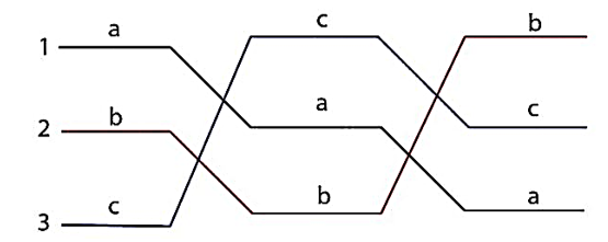
The transposition association of the conductor can sincerely show within the following the parent. The conductor in role 1, function 2 and role three changes in a particular arrangement to reduce the effect of capacitance and the electrostatic unbalanced voltages.
Why transposition arrangement is located
The transposition underneath energy strains lessen the electrostatic unbalance a number of the three stages. It extensively utilized to stabilize the voltage unbalance.
The transposition arrangement of excessive voltage strains also allows to lessen the machine strength loss.
In addition to this, we've evolved transposition machine for unmarried circuit tower the usage of equal anxiety tower with decreased deviation angle.
Transposition arrangement of electricity line also allows to lessen the effect of inductive coupling.
So could be benefited by reducing one extra tower design, approval, and effects in a discount of basic mission time, etc.
Its miles proved extra in your price range solution, in contrast of the traditional transposition gadget.
Approach for transposition association
With the non-stop growth in call for strength, loads of latest transmission line assignment are coming, and simultaneously it has emerged as very vital to finish the line in shortest feasible time.
For traces longer than a hundred km to 150 km, transposition of stages achieved with a unique tower, to reduce electrical line losses.
There's need to adopt specific strategies of transposition arrangement, which isn't always most effective price powerful however additionally it is able to
Store the execution time with reduced engineering hobby. The brand-new method proposed herewith basically simplifies the engineering hobby, and expedites the venture finishing touch following are the principle element of the proposed method of transposition.
Fig. Shows the 3 conductors a, b and c of an inductance of three segment overhead line sporting currents ia, ib and ic respectively. Allow d1, d2 and d3 be the spacings among the conductors as proven. Let us further anticipate that the loads are balanced i.e., Ia + ib + ic = zero. Don't forget the flux linkages with conductor a. There might be flux linkages with conductor a due to its very own modern-day and additionally due to the mutual inductance outcomes of ib and ic.
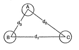
Flux linkages with conductor a because of its own current

Flux linkages with conductor a due to contemporary ib

Flux linkages with conductor a due to contemporary ic 

Total flux linkages with conductor a is nr


1.Symmetrical spacing:
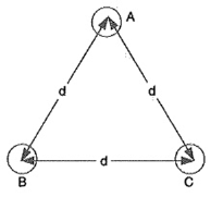
If the three conductors a, b and c are located symmetrically at the corners of an equilateral triangle of facet d, then, d1 = d2 = d3 = d. Beneath such conditions, the flux linkages with conductor a come to be:


 werber-turns/m
Inductance of three segment overhead line


Inductance of conductor a,
Inductance of 3 segment overhead line
Derived in a comparable way, the expressions for inductance are the same for conductors b and c.
2.Unsymmetrical spacing:
When three-segment line conductors are not equidistant from each other, the conductor spacing is said to be unsymmetrical. Underneath such situations, the flux linkages and inductance of 3 segment overhead line of each, phase aren't the identical.
An exceptional inductance in every phase result in unequal voltage drops within the 3 phases even supposing the currents inside the conductors are balanced. Consequently, the voltage on the receiving quit will not be the identical for all stages.
Simply so voltage drops are same in all conductors, we commonly interchange the positions of the conductors at everyday intervals alongside the line in order that each conductor occupies the unique role of every other conductor over an identical distance.
Such an alternate of positions is referred to as transposition. Fig. 9.9 suggests the transposed line. The phase conductors are specific as a, b and c and the positions occupied are numbered 1, 2 and three. The impact of transposition is that every conductor has the same common inductance.

Inductance of 3 section overhead line
Fig. Indicates a 3-segment transposed line having unsymmetrical spacing. Allow us to expect that each of the 3 sections is 1 m in duration. Allow us to similarly assume balanced conditions i.e., ia + ib + ic = 0. Allow the line currents be:


Inductance of 3 segment overhead line
As proved above, the entire flux linkages in line with metre length of conductor a is

Inductance of 3 segment overhead line
Setting the values of ia, ib and ic, we get,


Inductance of three phase overhead line
Inductance of conductor a is

Inductance of 3 segment overhead line
Similarly, inductance of conductors b and c will be:


Inductance of three segment overhead line
Inductance of every line conductor


Inductance of three section overhead line
If we examine the components of inductance of an unsymmetrically spaced transposed line with that of symmetrically spaced line, we discover that inductance of 3 segment overhead line of every line conductor inside the cases could be identical if d=∛d1d2d3. The space d is referred to as equal equilateral spacing for unsymmetrically transposed line.
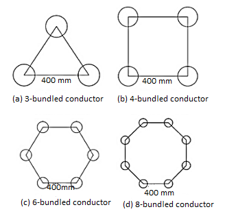
Single stranded conductors are used in transmission gadget normally as much as 220 kv. But it isn't viable to use single-stranded conductor for the voltage above 220 kv systems.
For extremely excessive voltage system, hollow conductor can be used to optimize the go with the flow of present day through it. But erection and protection of hollow conductors inside the ∑hv machine aren't low cost.
The problem may be solved via the usage of bundled conductors in preference to hole conductor inside the electric transmission gadget above 220 kv voltage level.
What's bundled conductor?
We name bundled conductor to the ones conductors which form from or greater stranded conductors, bundled collectively to get more modern carrying potential.
Right here, we use or greater stranded conductors consistent with phase. Also, to boom the modern-day wearing capability of the device, a bundle conductor additionally contributes numerous facilities to the electrical transmission machine.
A bundled conductor reduces the reactance of the electrical transmission line. It additionally reduces voltage gradient, corona loss, radio interference, surge impedance of the transmission lines.
Via making bundle conductor, the geometric imply radius (gmr) of the conductor improved. As the self gmr of the conductor increases, the inductance of the conductor decreases. Theoretically, there is an ultimate sub-conductor spacing in package deal conductor on the way to supply minimal voltage gradient on the floor of package deal conductor. The superior spacing among sub-conductors for decreasing voltage gradient is 8 to 10 instances of the diameter of the conductor.
Because the voltage gradient receives decreased, the radio interference additionally receives reduced.
As the inductance of the bundled conductor is reduced, the surge impedance of the line is decreased have become the components of surge impedance is
In which l is the inductance according to phase in keeping with unit duration, and c is the capacitance per phase consistent with unit length of the transmission line.
Because the surge impedance gets decreased because of bundling the conductor, the surge impedance loading, of the conductor gets extended. Accelerated surge impedance loading makes the transmission potential of the system more.
To this point we've got mentioned three-segment systems which have handiest one conductor in step with phase. But for extra excessive voltage strains corona causes a big trouble if the conductor has best one conductor consistent with phase. Corona takes place when the floor ability gradient of a conductor exceeds the dielectric strength of the encompassing air. This causes ionization of the place near the conductor.
Corona produces electricity loss. It also reasons interference with conversation channels. Corona manifests itself with a hissing sound and ozone discharge. Due to the fact most long-distance electricity strains in India are both 220 kv or 400 kv, avoidance of the occurrence of corona is perfect.
The excessive voltage surface gradient is reduced significantly via having two or extra conductors in line with segment in close proximity. That is known as conductor bundling. The conductors are bundled in corporations of two, 3 or four as proven in fig. 1.10. The conductors of a package deal are separated at normal periods with spacer dampers that save you clashing of the conductors and save you them from swaying within the wind. In addition, they connect the conductors in parallel.
The geometric mean radius (gmr) of -conductor bundle is given by means of

In which ds is the gmr of conductor. The gmr for 3-conductor and four-conductor bundles are given respectively by means of


The inductance of the bundled conductor is then given by way of
Where n=2,3 ....

Wherein the geometric imply distance is calculated assuming that the center of a round conductor is the same as that of the middle of the package.
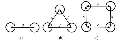
Fig. Bundled conductors: (a) 2-conductor, (b) 3-conductor and (c) 4-conductor bundles
A steady direct current flowing via the conductors is uniformly disbursed over the complete move-section of the conductor. However, an alternating cutting-edge flowing via the conductor does no longer distribute uniformly, as an alternative it has a tendency to pay attention near the floor of the conductor as proven inside the figure. That is called skin effect in transmission line.
Skin effect in transmission line:
As a result, the tendency of an alternating current to pay attention close to the surface of the conductor is called skin impact in transmission line.
Due to proximity and skin impact, the powerful vicinity of the pass-phase of the conductor via which modern is to waft is decreased. This will increase the resistance of conductor while sporting an alternating current. The purpose of skin effect in transmission line is explained beneath:
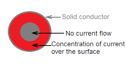
Normally, a stranded conductor is used and each strand includes a small a part of the cutting-edge. Every conductor strand, close to the center, is surrounded by using a more magnetic flux and therefore has larger inductance than that strand close to the floor.
The high reactance (opposition) of inner stands restricts the float of modern-day inside the middle and causes it to float near the surface of the conductor which produces proximity and skin impact.
How to lessen proximity and skin effect in transmission line:
The proximity and skin impact in transmission line relies upon the subsequent elements:
Nature of material.
- The diameter of cord – the skin effect increases with the diameter of wire.
- The shape of cord – the skin effect is lesser for stranded conductor than the solid conductor.
- Frequency – the skin effect increases with the increase in frequency. Whilst the frequency is zero (dc), there's no inductance and for this reason the present day is uniformly allotted over the complete go-section of the conductor. No skin effect. It is profitable to mention here that skin effect is negligible while the frequency is much less (underneath 50 hz) and conductor diameter is small (beneath 1 cm).
By means of using these facts properly, skin effect may be decreased considerably.
Proximity effect in transmission lines:
Inside the proximity and skin impact, the flux installation inside the conductor itself turned into taken into consideration and it turned into assumed that there may be no other current sporting conductor close by. This flux produces a nonuniform distribution of cutting-edge in the conductor referred to as skin impact.
But, within the transmission traces, there are (one or) contemporary wearing conductors located nearby and their magnetic flux links with the conductor below attention. The effect of this flux is extra within the closer 1/2 of the conductor than the farther.
Whilst the conductors convey currents within the opposite directions the fields set-up will tend to purpose an increase in the modern density within the adjacent quantities whereas whilst the currents are within the identical instructions the modern density is increased within the farther components of the conductor. This outcome the distribution of present day in the conductor.
Hence, the flux installation by means of the nearby modern sporting conductor effects the distribution of current within the conductor. This impact is known as proximity impact in transmission lines. For this reason, the proximity effect in transmission strains additionally consequences within the boom in resistance of the conductor.
Do not forget a capacitance of two wire line shown in fig. Three.3 excited from an unmarried-phase supply. The road develops same and opposite sinusoidal expenses on the two conductors which may be represented as phasors qa and qb in order that qa = — qb.
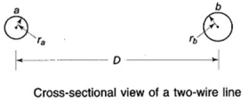
Capacitance of two wire line
The capability difference vab can be written in phrases of the contributions made by way of qa and qb by means of use of eq. (3.2) with associated assumptions (i.e., D/r is massive and ground is some distance away). Thus,

 we have

The line capacitance cab is then
Or

If


The associated line charging contemporary is

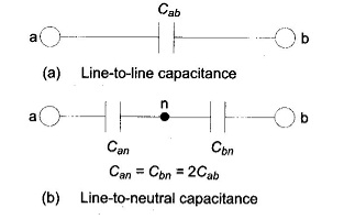
Capacitance of two wire line
As proven in fig. (a) and (b) the line-to-line capacitance can be equivalently taken into consideration as equal capacitances is collection. The voltage throughout the lines divides similarly among the capacitances such that the neutral point n is on the ground capacity. The capacitance of each line to neutral is then given through

Capacitance of two wire line
The assumptions inherent inside the above derivation are:
1. The charge at the surface of each conductor is thought to be uniformly distributed, however this is strictly no longer correct.
If non-uniformity of rate distribution is taken into consideration, then

If d/2r » 1, the above expression reduces to that of eq. And the mistake as a result of the idea of uniform rate distribution is negligible.
2. The move-segment of each the conductors are assumed to be round, at the same time as in actual practice stranded conductors are used. The usage of the radius of the circumscribing circle for a stranded conductor causes insignificant errors.
In a capacitance of three segment overhead line, the capacitance of every conductor is considered as opposed to capacitance from conductor to conductor. Right here, once more instances stand up viz., symmetrical spacing and unsymmetrical spacing.
Capacitance of three section overhead line
1.Symmetrical spacing:
Fig. Nine.24 shows the 3 conductors a, b and c of the 3-segment overhead transmission line having charges qa, qb and quality controls in line with metre length respectively. Let the conductors be equidistant (d metres) from every different. We shall locate the capacitance from line conductor to impartial in this symmetrically spaced line. Relating to fig. 9.24, average capacity distinction between conductor a and infinite neutral plane is given with the aid of


Capacitance of three phase overhead line
Assuming balanced deliver, we have


Capacitance of conductor a w.r.t neutral,


Capacitance of 3 section overhead line
Observe that this equation is identical to capacitance to impartial for two-cord line. Derived in a similar manner, the expressions for capacitance are the same for conductors b and c.
2.Unsymmetrical spacing:
Fig. Indicates a 3-phase transposed line having unsymmetrical spacing. Allow us to count on balanced conditions i.e., Qa + qb + qc = zero.

Considering all the three sections of the transposed line for section a,
Potential of 1st position

Potential of 2nd position

Potential of 23rd position

Average voltage on conductor a is
As
 therefore,


Capacitance from conductor to neutral is

In calculating the impact of earth on capacitance of transmission line, the presence of earth changed into omitted, to this point. The effect of earth on capacitance of transmission line may be effortlessly taken into consideration by way of the method of images.
Method of images:
The electric subject of transmission line conductors have to comply with the presence of the earth under. The earth for this reason can be assumed to be a wonderfully carrying out horizontal sheet of countless volume which therefore acts like an equipotential surface.
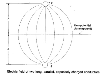
The electrical field of two lengthy, parallel conductors charged +q and -q consistent with unit is such that it has a 0-capacity aircraft midway between the conductors as proven in fig. If an accomplishing sheet of infinite dimensions is placed on the zero-ability plane, the electrical subject remains undisturbed. In addition, if the conductor sporting charge -q is now eliminated, the electric subject above the engaging in sheet stays intact, even as that underneath it vanishes. The usage of these well-known outcomes in reverse, we can also equivalently replace the presence of floor beneath a charged conductor via a fictitious conductor having equal and opposite price and placed as some distance beneath the floor of floor because the overhead conductor above it—any such fictitious conductor is the mirror image of the overhead conductor. This technique of making the same electric powered discipline as within the presence of earth is referred to as the approach of pictures at the beginning cautioned by using lord kelvin.
Effect of earth on capacitance of transmission line
Capacitance of a single-segment line:
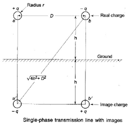
Don't forget an unmarried-section line shown in fig. It is required to calculate its capacitance of transmission line taking the presence of earth under consideration by way of the technique of pics defined above. The equation for the voltage drops vab as decided by means of the two charged conductors a and b, and their images a’ and b’ can be written as follows:

Substituting the values of different prices and simplifying, we get

Impact of earth on capacitance of transmission line
It without delay follows that
And
 to neutral
Effect of earth on transmission line capacitance
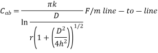
It is observed from the above equation that the presence of earth modifies the radius r to r (1 + (d2/4h2)) half of. For h big in comparison to d (that is the case typically), the effect of earth online capacitance is of negligible order.
Capacitance of a three-phase line:
The method of images can similarly be implemented for the calculation of capacitance of transmission line of a 3-section line, proven in fig. 3.10. The line is considered to be absolutely transposed. The conductors a, b and c carry the charges qa, qb and quality controls and occupy positions 1, 2, and three, respectively, in the first phase of the transposition cycle. The impact of earth is simulated by using photo conductors with costs -qa, -qb and -quality controls respectively, as shown.
The equations for the 3 sections of the transposition cycle may be written for the voltage drop vab as decided by way of the 3 charged conductors and their pics. With conductor a in role 1, b in position 2, and c in position 3,

Similar equations for vab may be written for the second and 1/3 sections of the transposition cycle. If the fairly accurate assumption of consistent charge in line with unit length of the conductor during the transmission cycle is made, the average fee of vab for the 3 sections of the cycle is given by way of

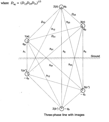
Effect of earth on capacitance of transmission line
The equation for the average cost of the phasor vac is located in a similar way. Intending at the traces of sec. 3.6 and using vab + vac = 3van and qa + qb + quality controls = 0, we in the end acquired the subsequent expression for the capacitance to neutral.
 to neutral
Or
 to neutral
Evaluating eqs., it is glaring that the effect of earth is to growth the capacitance of a line. If the conductors are excessive above earth compared to the distances amongst them, the impact of earth on the capacitance of three-phase lines can be neglected.
A bundled conductor line is shown in fig. Four.34. The conductors of any one bundle are in parallel and its miles assumed that the price per bundle divides similarly the various conductors of the package deal as dab >> s. Also dab – s ≃ dab + s ≃ dab for the identical cause. The effects acquired with those assumptions are fairly accurate for standard spacings. Hence if rate on phase a is qa, then a and a’ have a rate of qa/2 every. Similarly, the price is equally divided for stages b and c.
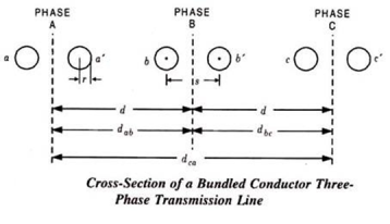
Now, writing an equation for the voltage from conductor a to conductor b, we've got,


Considering the line to be transposed and proceeding within the usual way, the very last result can be,

Mutual gmd of the circuit may be decided,

Self gmd, ds is determined besides that for r’, r is used.
If parallel 3-phase circuits are near collectively, either at the same tower as in determine 4. Three, or on the identical right-of-manner, there are mutual inductive and capacitive couplings among the two circuits. Whilst calculating the equivalent collection impedance and shunt admittance matrices, those couplings should not be left out until the spacing between the circuits is large.
Corona discharge (additionally known as the corona impact) is an electrical discharge resulting from the ionization of a fluid such as air surrounding a conductor this is electrically charged. The corona impact will occur in excessive voltage systems except enough care is taken to limit the power of the encompassing electric powered subject.
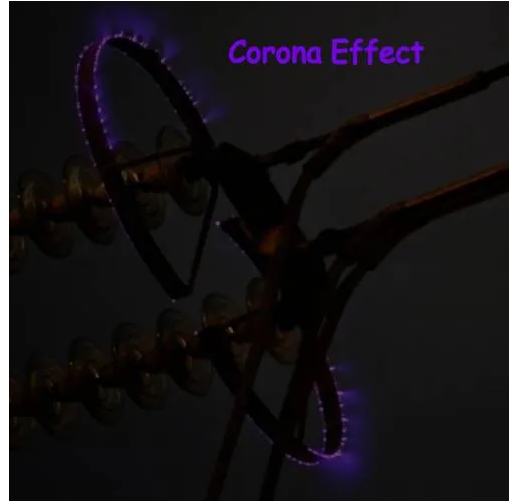
Corona discharge can reason an audible hissing or cracking noise as it ionizes the air across the conductors. This is common in high voltage electric energy transmission traces. The corona impact can also produce a violet glow, manufacturing of ozone fuel across the conductor, radio interference, and electrical strength loss.
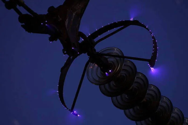
Corona discharge on a 500 kv overhead power line
What is the corona impact?
The corona effect occurs clearly due to the reality that air isn't always a super insulator – containing many free electrons and ions under ordinary situations. While an electric subject is installed in the air among conductors, the unfastened ions and electrons inside the air will enjoy a force. Because of this impact, the ions and loose electrons get improved and moved inside the opposite route.
The charged particles at some point of their motion collide with one another and also with gradual-transferring uncharged molecules. For this reason, the range of charged debris increases swiftly. If the electrical area is strong sufficient, a dielectric breakdown of air will arise and an arc will form among the conductors.
Electric powered energy transmission deals with the majority switch of electrical power, from generating stations located many kilometers far away from the principle consumption facilities or the cities. Because of this, the long-distance transmission conductors are of maximum necessity for effective electricity switch – which in-certainly consequences in big losses across the system.
Minimizing these energy losses has been a chief project for strength engineers. Corona discharge can appreciably reduce the efficiency of ehv (extra excessive voltage) strains in strength systems.
Two elements are crucial for corona discharge to arise:
Alternating electric ability difference ought to be supplied across the line.
The spacing of the conductors, should be big sufficient compared to the line diameter.
Corona discharge:
When an alternating current is made to glide across two conductors of a transmission line whose spacing is huge compared to their diameters, the air surrounding the conductors (composed of ions) is subjected to dielectric strain.
At low values of the deliver voltage, not anything takes place because the strain is just too small to ionize the air out of doors. But when the ability distinction increases past some threshold fee (known as the essential disruptive voltage), the field strength will become sturdy enough for the air surrounding the conductors to dissociated into ions – making it conductive. This crucial disruptive voltage takes place at approximately 30 kv.
The ionized air effects in electric discharge across the conductors (due to the float of these ions). This gives upward push to a faint luminescent glow, together with the hissing sound followed via the liberation of ozone.
This phenomenon of electrical discharge happening in high voltage transmission lines is referred to as the corona impact. If the voltage across the lines continues to growth, the glow and hissing noise becomes increasingly extreme – inducing an excessive strength loss into the gadget.
Elements affecting corona loss:
The line voltage of the conductor is the principle figuring out aspect for corona discharge in transmission lines. At low values of voltage (lesser than the essential disruptive voltage) the stress at the air is not excessive enough to purpose dielectric breakdown – and hence no electric discharge occurs.
With increasing voltage, the corona effect in a transmission line takes place due to the ionization of atmospheric air surrounding the conductors – it is especially stricken by the conditions of the cable in addition to the bodily nation of the environment. The primary
Factors affecting corona discharge are:
- Atmospheric conditions
- Condition of conductors
- Spacing among conductors
Atmospheric conditions:
We've got proved that the voltage gradient for dielectric breakdown of air is directly proportional to the density of air. As a result, in a stormy day, because of continuous air float, the quantity of ions present surrounding the conductor is a way extra than normal, and hence it’s much more likely to have electric discharge in transmission traces on this type of day, in comparison to an afternoon with the pretty clear weather. The device needs to be designed thinking about those intense situations.
Circumstance of conductors:
This specific phenomenon relies upon highly at the conductors and its physical circumstance. It has an inverse proportionality courting with the diameter of the conductors. I.E., with the boom in diameter, the effect of corona on strength device reduces substantially. Also, the presence of dust or roughness of the conductor reduces the critical breakdown voltage, making the conductors greater prone to corona losses. As a result, in maximum cities and business areas having excessive pollution, this component is of affordable importance to counter the unwell consequences it has on the machine.
Spacing among conductors:
As already cited, for corona to arise within the spacing between the strains correctly have to be tons better in comparison to its diameter, however if the duration receives accelerated past a sure limit, the dielectric pressure at the air reduces, and therefore, the impact of corona reduces as well. If the spacing is made too huge, then corona for that place of the transmission line might not arise at all.
Lowering corona discharge
Corona discharge always consequences in electricity loss. Energy is lost in the shape of mild, sound, warmness, and chemical reactions. Although those losses are personally small, through the years they are able to add as much as massive energy loss in high voltage networks.
Corona discharge can be reduced via:
Growing the conductor size: a larger conductor diameter consequence in a lower in the corona impact.
Increasing the distance among conductors: growing conductor spacing decreases the corona effect.
Using bundled conductors: bundled conductors increase the effective diameter of the conductor – hence decreasing the corona effect.
The use of corona rings: the electrical subject is more potent wherein there is a sharp conductor curvature. Because of this corona discharge happens first at the pointy factors, edges, and corners. Corona earrings reduce the corona effect by ‘rounding out’ conductors (i.e., Making them much less sharp). They may be used on the terminals of very excessive voltage gadget (including on the bushings of high voltage transformers). A corona ring is electrically connected to the excessive voltage conductor, encircling the factors wherein the corona effect is maximum probably to arise. This encircling appreciably reduces the sharpness of the floor of the conductor – dispensing the charge across a wider vicinity. This in turn reduces corona discharge.
References:
[1] J. Grainger and W. D. Stevenson, “Power System Analysis”, McGraw Hill Education,
1994.
[2] O. I. Elgerd, “Electric Energy Systems Theory”, McGraw Hill Education, 1995.
[3] D. P. Kothari and I. J. Nagrath, “Modern Power System Analysis”, McGraw Hill
Education, 4th Edition, 2011.
[4] B. M. Weedy, B. J. Cory, N. Jenkins, J. Ekanayake and G. Strbac, “Electric Power
Systems”, Wiley, 5th Edition, 2012.
[5] C.L. Wadhwa, “Electrical Power Systems”, New Age International Publishers, 6th
Edition.
[6] A. R. Bergen and V. Vittal, “Power System Analysis”, Pearson Education Inc, 1999.