Unit - 3
Representation of Short, medium and long Transmission Line
The category of the transmission traces depends on its voltage and the length of the conductor. The transmission line is the medium of transferring the power from the generating station to the burden center.
It is mainly classified into two types. They're the
1) AC transmission line
- Short-transmission line
- Medium transmission line
- Pi model of a medium transmission line
- T model of a medium transmission line
- Long transmission line
2)Dc transmission line
1. Ac transmission line
The transmission line has resistance r, inductance l, capacitance c and the shunt or leakage conductance g. Those parameters at the side of the weight and the transmission line decide the performance of the road.
The time period overall performance approach the sending stop voltage, sending cease currents, sending cease energy aspect, energy loss within the line, efficiency of the transmission line, adjust and restrict of electricity float during performance and transmission, law and boundaries of power at some stage in steady nation and short circumstance.
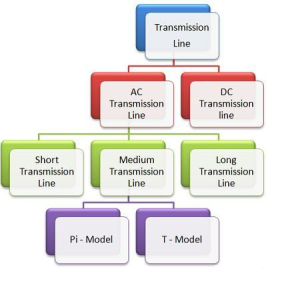
The contrast chart of the transmission line is proven inside the determine below.
Type-of-transmission-line
Short transmission line
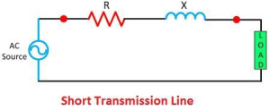
If the line isn't always greater than 80 kv or if the voltage isn't over than sixty-six kv then the road is called the short transmission line. The capacitance of the line is ruled via their period. The impact of capacitance on the short transmission line is negligible, however for cable in which the gap among the conductor is small, the effect of capacitance can't be neglected. At the same time as reading the performance of the fast transmission line only resistance and the inductance of the line is calculated.
Medium transmission line
The road that is starting from eighty to 240 km is termed as a medium transmission line. The capacitance of the medium transmission line can't be neglected. The capacitance of the medium transmission line is considered to be lumped at one or greater factor of the traces. The impact of the line is greater at excessive frequency, and their leakages inductance and capacitance is taken into consideration to be disregarded. The medium transmission line is sub-divided into pi – model and t – model.
Pi model of a medium transmission line
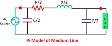
In nominal pi model, it is assumed that the 1/2 of the capacitance pay attention on the every end of the road.
T – model of a medium transmission line

In t model, it is assumed that the capacitance is focused at the center of the road.
Medium-transmission-line-pi-model
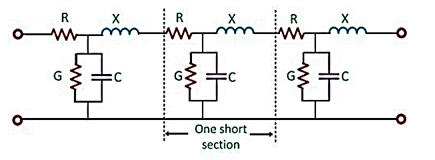
Long transmission line
The road having a duration extra than 240 km is considered a long transmission line. All the 4 parameters (resistance, inductance, capacitance, and leakage conductance) are observed to be equally dispensed alongside the whole period of the road.
2. Dc transmission line
The dc transmission is in particular used for the bulk energy transmission. For long distance transmission, the dc is less luxurious and feature low electrical losses. The fee of the dc transmission structures is better for short distance transmission line as it requires more convertible equipment as compared to an ac device.

The converter station converts the ac to dc on the sending cease and dc to ac at the load quit of the road. One of the main gain of the dc machine is that it allows the power transmission among two unsynchronized ac system.
An equivalent circuit is a kind of electric circuit that may be a simplified representation of a greater complex electrical circuit. An equal circuit can take a complex circuit with many extraordinary sources of voltages, currents and resistances and have those assets blended the use of right techniques to make it much less complex and more easily comprehended.
Taking a complicated electric circuit and changing it with an equal circuit is an extremely good choice whilst trying to investigate the general circuit.
It's far crucial, however, to have sound understanding of electrical circuits and recognize what can and can't be simplified, in addition to the way to simplify it.
It's far essential to know whilst objects including voltage, contemporary and resistance can be brought collectively and once they cannot.
An equivalent circuit can be very useful so long as the terminal properties end up being the same as the unique, extra complex circuit.
There are 3 most important type of overhead transmission lines:
Short transmission line – the road period is as much as 60 km and the line voltage is comparatively low less than 20kv.
Medium transmission line – the road period is between 60 km to 160 km and the road voltage is between 20kv to 100kv.
Long transmission line – the line duration is greater than 160 km and the line voltage is excessive more than 100kv.
Anything may be the class of transmission line, the primary purpose is to transmit strength from one give up to every other.


Like different electrical machine, the transmission community additionally could have a few energy loss and voltage drop for the duration of transmitting energy from sending quit to receiving give up. Subsequently, performance of transmission line may be decided by means of its performance and voltage regulation.
Voltage law of transmission line is measure of change of receiving stop voltage from no-load to full load circumstance.
Transmission line
Every transmission line may have 3 basic electric parameters. The conductors of the road can have electrical resistance, inductance, and capacitance. As the transmission line is a set of conductors being run from one vicinity to another supported by using transmission towers, the parameters are dispensed uniformly alongside the line.
The electrical power is transmitted over a transmission line with a pace of mild that is three × 108 m ⁄ sec. Frequency of the electricity is 50 Hz. The wave length of the voltage and cutting-edge of the strength may be determined by the equation given under,
Therefore,


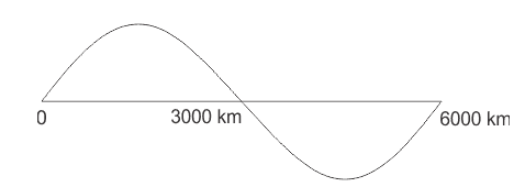
Voltage distribution of 50hz supply
F.λ = v in which, f is electricity frequency, λ is wave length and υ is the speed of mild.
As a result, the wave length of the transmitting energy is quite lengthy compared to the commonly used line duration of transmission line.
Because of this, the transmission line, with period less than 160 km, the parameters are assumed to be lumped and now not allotted. Such strains are known as electrically short transmission line. This electrically quick transmission traces are once more categorized as short transmission line (period as much as 60 km) and medium transmission line (duration between 60 and a hundred and sixty km).
The capacitive parameter of brief transmission line is neglected whereas in case of medium length line the, capacitance is thought to be lumped on the middle of the line or 1/2 of the capacitance can be considered to be lumped at every ends of the transmission line. Traces with duration greater than 160 km, the parameters are considered to be disbursed over the line. This is referred to as long transmission line.
Manage of voltage profile of transmission line on the receiving bus in the essential two-bus device changed into discussed already. Though the identical preferred conclusions preserve for an interconnected device, it's miles essential to talk about this problem in extra element.
At a bus with technology, voltage can be simply controlled by using adjusting generator excitation. That is illustrated with the aid of fig. wherein the equivalent generator on the it bus is modeled by using a synchronous reactance (resistance is assumed negligible) and voltage in the back of synchronous reactance.
It right away follows upon application of eqs.
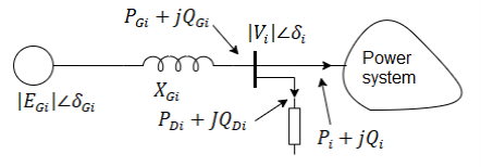


Vi the load flow solution, these values can be carried out on the bus via adjusting generator excitation to breakthrough eq. And by way of adjusting the governor setting in order that power input to generator from turbine is pgi plus losses, ensuing in load angle of (δgi – δi) corresponding to eq.
If Egi demand exceeds the capacity of generators, var generators (synchronous or static capacitor) ought to be used to adjust the nearby load.
If follows from above that to control the voltage profile of transmission line of an inter-connected gadget, buses with turbines are usually made pv (i.e. Voltage manage) buses. Load glide solution then gives the voltage levels on the load buses.
If a number of the weight bus voltages workout to be much less than the specified lower voltage restricts, it is indicative of the fact that the reactive power waft potential of transmission strains for exact voltage limits cannot meet the reactive load call for (reactive line waft from bus i to bus okvk. This example can be remedied via putting in var generators at a number of the weight buses.
These buses within the load glide analysis are then regarded as pv buses with the ensuing solution giving the requisite values of var (jqc) injection at those buses.
The truth that wonderful var injection at any bus of an interconnected device could help to raise the voltage at the bus is effortlessly established below: discern 6.15a suggests the Thevenin equal circuit of the electricity machine as visible from the it bus. Obviously, eth = vi. If now jqc from var generator is injected into this bus as proven in fig. b, we've from eq.


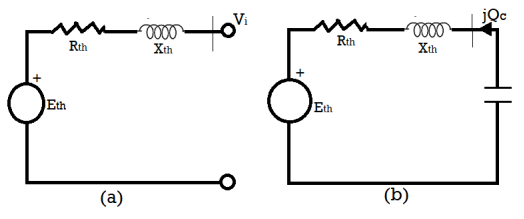
Due to the fact we're considering a voltage upward push of some percent may be further approximated as

The Ferranti effect is a phenomenon that describes the boom in voltage that occurs at the receiving give up of a long transmission line relative to the voltage at the sending give up. The Ferranti effect is extra everyday while the weight could be very small, or no load is hooked up (i.e., An open circuit). The Ferranti impact can be stated as a factor, or as a percent boom.
In standard practice we know, that for all electrical structures present day flows from the region of better ability to the location of decrease potential, to atone for the electric potential difference that exists within the device. In all practical instances, the sending give up voltage is better than the receiving cease because of line losses, so modern-day flows from the source or the deliver quit to the burden.
But sir S.Z. Ferranti, in the yr. 1890, came up with a dazzling concept about medium transmission line or long-distance transmission strains suggesting that during case of light loading or no-load operation of the transmission system, the receiving quit voltage frequently will increase beyond the sending end voltage, main to a phenomenon called Ferranti impact in a power device.
Ferranti effect in transmission line
An extended transmission line can be taken into consideration to compose a notably excessive amount of capacitance and inductance allotted throughout the complete length of the road. Ferranti effect happens whilst present day drawn by means of the disbursed capacitance of the line itself is extra than the contemporary associated with the weight at the receiving stop of the road (for the duration of light or no load).
This capacitor charging modern ends in a voltage drop throughout the line inductor of the transmission device that's in section with the sending cease voltages. This voltage drop continues on growing additively as we move toward the weight quit of the road and sooner or later, the receiving end voltage tends to get larger than implemented voltage leading to the phenomena referred to as Ferranti impact in strength machine. We illustrate that with the help of a phasor diagram beneath.
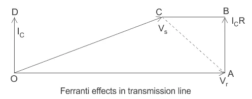
As a consequence, each the capacitance and inductor effect of transmission line are similarly liable for this unique phenomenon to arise, and subsequently Ferranti effect is negligible in case of a short transmission line because the inductor of this kind of line is almost considered to be nearing zero.
In popular for a 300 km line operating at a frequency of fifty Hz, the no-load receiving quit voltage has been observed to be 5% better than the sending stop voltage.
Now for the evaluation of the Ferranti impact let us take into account the phasor diagrams shown above.
Right here, vr is considered to be the reference phasor, represented by OA.
Thus 
Capacitance current 
Now sending end voltage 


Now 
This is represented with the aid of the phasor oc.
Now in case of a “long transmission line,” it's been practically found that the road electric resistance is negligibly small compared to the line reactance. Therefore, we can assume the period of the phasor ic r = zero; we can do not forget the upward thrust inside the voltage is best due to oa – oc = reactive drop inside the line.
Now if we bear in mind c0 and l0 are the values of capacitance and inductor according to km of the transmission line, wherein l is the period of the road.
Thus capacitive reactance 
On account that, in case of an extended transmission line, the capacitance is shipped during its duration, the average current flowing is,

Now the inductive reactance of the line 
Accordingly, the rise in voltage due to line inductor is given via,

Voltage rise 
From the above equation it's miles clearly obvious, that the upward push in voltage on the receiving give up is at once proportional to the rectangular of the line duration, and consequently in case of an extended transmission line it keeps increasing with length, or even is going past the applied sending stop voltage at times, leading to the phenomena called Ferranti effect.
Thus far the transmission line overall performance equation became supplied in the shape of voltage and current relationships among sending-and receiving-ends. Because loads are greater often expressed in terms of real (watts/kw) and reactive (vars/ kvar) electricity, it's miles convenient to cope with transmission line equations within the shape of sending- and receiving-cease complicated power and voltages. Even as the problem of electricity float via a transmission line in a well-known community can be discussed later, the power waft thru transmission line concepts involved are illustrated right here thru an unmarried transmission line (2-node/2-bus device) as shown in fig.

A Two Bus system
Strength goes with the flow through a transmission line
Let us take the receiving-ceasevrzero°) and permit the sending-cease voltage lead it by means of a perspective ∠δ). The perspective δ is referred to as the torque attitude.
The complex strength leaving the receiving-quit and getting into the sending-cease of the transmission line may be expressed as (on consistent with phase foundation)


Receiving- and sending-stop currents can, but, be expressed in phrases of receiving- and sending-end voltages as


Allow a, b, d, the transmission line constants, be written as

Consequently, we are able to write


Substituting for  in eq. We get


Energy go with the flow through a transmission line
Inside the above equations sr and ss are consistent with phase complex voltamperes, even as vr and vs are expressed in in keeping with section volts. If vr and vs are expressed in kv line, then the 3-segment receiving-stop complex power is given by way of


This certainly is similar to eq. The equal result holds for ss. Accordingly we see that eqs. Supply the 3-phase ma if vs and v are expressed in kc line.
If e. Is expressed in actual and imaginary elements, we will write the actual and reactive powers on the receiving-end as


Strength flow thru a transmission line similarly, the actual and reactive powers at sending-end are


Electricity flow thru a transmission line
It is easy to look from eq. That the acquired energy pr may be most at

Such that

For this reason the weight have to draw this a good deal main mvar so one can get hold of the most actual power.
Bear in mind now the special case of a short line with a chain impedance z. Now

Substituting those in eqs., we get the simplified effects for the short line as


For the receiving-quit and for the sending-end


Power goes with the flow thru a transmission line
The above quick line equation will also apply for a long line while the road is changed by its equal- π (or nominal- π) and the shunt admittances are lumped with the receiving-stop load and sending-give up era.
From eq., the most receiving-end strength is acquired, when δ=θ
So that

Now 

Commonly the resistance of a transmission line is small as compared to its reactance (on the grounds that it's miles important to hold a high performance of transmission), so that θ= tan-1 x/r ≈ 90∘; wherein z = r + jx. The receiving-end eqs. Can then be approximated as


Strength waft thru a transmission line equation can be further simplified by means of assuming cos δ ≈ 1, in view that δ is normally small. Accordingly

Allow, the magnitude of voltage drop throughout the transmission line.

Numerous vital conclusions that easily comply with from eqs. Are enumerated underneath:

For r ≈ 0 (that's a valid approximation for a transmission line) the actual energy transferred to the receiving-cease is proportional to sin δ (≈ δ for small values of δ), whilst the reactive energy is proportional to the significance of the voltage drop throughout the road.
The real energy acquired is most for δ = 90° and has a cost path, δ is limited to values nicely under ninety° from considerations of balance.
Most real electricity transferred for. A given line (constant x) can be expanded by means of raising its voltage level. It's far from this consideration that voltage levels are being gradually driven as much as transmit large chunks of strength waft thru transmission line over longer distances warranted by massive length generating
For terribly lengthy strains voltage stage cannot be raised beyond the boundaries located by present-day high voltage technology. To boom electricity transmitted in such cases, the most effective choice is to lessen the road reactance. This is achieved through including series capacitors inside the line. Series capacitors would of direction growth the severity of line over voltages underneath switching conditions.
As stated in 1 above, the vars (lagging reactive power) added by using a line is proportional to the line voltage drop and is unbiased of δ. Therefore, in a transmission gadget if the vars call for of the load is huge, the voltage profile at that factor tends to sag as a substitute sharply. To maintain a favored voltage profile, the vars call for of the weight must be met domestically by way of using advantageous var generators (condensers).
A really more accurate yet approximate result expressing line voltage drop in terms of lively and reactive energy flow thru transmission line may be written at once from eq, i.e.


This result reduces to that of eq. If r = 0.
Surge impedance loading is a very critical parameter on the subject of the study of strength structures as it's far used inside the prediction of maximum loading capability of transmission strains.
However earlier than knowledge SIL, we first want to have a concept of what's surge impedance (zs). It could be described in two methods one an easier one and other a bit rigorous.
Approach 1
It's miles a well-known truth that an extended transmission strains (> 250 km) have disbursed inductance and capacitance as its inherent property. Whilst the road is charged, the capacitance component feeds reactive power to the line whilst the inductance factor absorbs the reactive electricity. Now if we take the balance of the two reactive powers we arrive at the subsequent equation
Capacitive var = inductive var

In which,
V = section voltage
I = line modern
Xc = capacitive reactance in keeping with section
Xl = inductive reactance in line with section
Upon simplifying

In which,
F = frequency of the gadget
L = inductance consistent with unit duration of the line
L = length of the road
For this reason, we get,

This quantity having the dimensions of resistance is the surge impedance. It could be taken into consideration as a simply resistive load which whilst related at the receiving stop of the line, the reactive electricity generated by using capacitive reactance will be absolutely absorbed by means of inductive reactance of the road.
It's far not anything however the function impedance (zc) of a lossless line.
Technique 2
From the rigorous answer of a long transmission line, we get the subsequent equation for voltage and modern-day at any point on the line at a distance x from the receiving end


In which,
Vx and ix = voltage and cutting-edge at point x
Vr and ir = voltage and contemporary at receiving stop
Zc = function impedance
δ = propagation constant


Z = series impedance in step with unit length in line with segment
Y = shunt admittance in step with unit period in line with phase
Setting the cost of δ in above equation of voltage we get

Wherein,


We look at that the immediately voltage includes phrases each of that's a characteristic of time and distance. As a result, they constitute travelling waves. The primary one is the nice exponential component representing a wave travelling in the direction of receiving give up and is for this reason called the incident wave. At the same time as the other component with negative exponential represents the reflected wave. At any factor along the line, the voltage is the sum of each the waves. The same is true for modern-day waves additionally.
Now, if assume the weight impedance (zl) is selected such that zl = zc, and we recognize

As a result

And hence the meditated wave vanishes. This type of line is called as infinite line. It seems to the supply that the road has no stop as it receives no pondered wave.
As a result, such an impedance which renders the road as limitless line is referred to as surge impedance. It has a price of approximately 400 ohms and segment perspective varying from zero to –15 diploma for overhead traces and around forty ohms for underground cables.
The term surge impedance is however used in connection with surges on the transmission line which may be due to lightning or switching, where the line losses may be unnoticed such that

Now that we have understood surge impedance, we can without difficulty define surge impedance loading.
Sil is defined as the power introduced through a line to a basically resistive load same in value to the surge impedance of that line. Hence, we will write

The unit of SIL is watt or mw.
Whilst the line is terminated with the aid of surge impedance the receiving end voltage is identical to the sending stop voltage and this example is known as flat voltage profile. The subsequent discern shows the voltage profile for extraordinary loading cases.
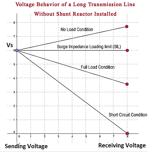
It needs to additionally be cited that surge impedance and consequently SIL is impartial of the length of the road. The fee of surge impedance may be the same at all of the points on the line and hence the voltage.
In case of a compensated line, the value of surge impedance can be modified hence as

Where, kse = % of series capacitive compensation with the aid of Cse

Kcsh = % of shunt capacitive compensation by csh

Klsh = % of shunt inductive compensation by lsh

The equation for sil will now use the modified zs.
In series compensation, the information is attached in series with the energy machine. It really works as a controllable voltage supply. Series inductance occurs in long transmission lines, and when a big cutting-edge flows this causes a huge voltage drop. To compensate, series capacitors are connected, decreasing the effect of the inductance.
Shunt compensation
In shunt compensation, electricity device is hooked up in shunt (parallel) with the facts. It really works as a controllable modern-day source. Shunt compensation is of kinds:
Shunt capacitive compensation
This technique is used to enhance the electricity element. On every occasion an inductive load is connected to the transmission line, power aspect lags because of lagging load contemporary. To compensate, a shunt capacitor is hooked up which attracts modern-day leading the supply voltage. The net end result is development in strength issue.
Shunt inductive compensation
This technique is used either while charging the transmission line, or, while there may be very low load at the receiving quit. Because of very low, or no load – very low current flows via the transmission line. Shunt capacitance within the transmission line causes voltage amplification (Ferranti impact). The receiving quit voltage may also come to be double the sending stop voltage (usually in case of very long transmission strains). To compensate, shunt inductors are connected throughout the transmission line.
Concept
In the case of a no-loss line, voltage significance at receiving quit is the same as voltage magnitude at sending stop: vs = vr=v. Transmission outcomes in a segment lag î´ that relies upon online reactance x.
As it is a no-loss line, lively energy p is the same at any factor of the road:
Reactive power at sending quit is the other of reactive electricity at receiving cease:
As î´ may be very small, energetic strength specifically depends on î´ while reactive strength especially relies upon on voltage magnitude.
Series compensation
Records for series compensation modify line impedance: x is reduced that allows you to growth the transmittable energetic electricity. But, extra reactive strength ought to be supplied.
Shunt compensation
Reactive present day is injected into the line to keep voltage value. Transmittable active electricity is elevated but greater reactive strength is to be supplied.
Examples of series compensation
Examples of records for series compensation (schematic)
Static synchronous series compensator (sssc)
Thyristor-controlled series capacitor (tcsc): a series capacitor bank is shunted by way of a thyristor-controlled reactor
Thyristor-controlled series reactor (tcsr): a series reactor bank is shunted by way of a thyristor-controlled reactor
Thyristor-switched series capacitor (tssc): a series capacitor bank is shunted by way of a thyristor-switched reactor
Thyristor-switched series reactor (tssr): a chain reactor bank is shunted with the aid of a thyristor-switched reactor
Transmission line series capacitor compensator after the country of the gadget had greater in-depth research, talked about that a few machine problems, inclusive of over-voltage level upward thrust, arc modern-day increases and the possibility of sub-synchronous resonance series capacitor compensator are derived from the inherent traits, via the have a look at concluded that after the series compensated transmission line wherein an inner failure, which includes the imposition of protecting measures is induced skip gap was to avoid immoderate stages of the device recuperation voltage and arc contemporary troubles which include an effective way to boom. In addition, proposed the installation of series compensation stations to reveal sub-synchronous resonance suppressed or secondary tool to suppress and save you system at sub synchronous resonance.
Use of series capacitor compensation method can improve lengthy-distance transmission strains ehv transmission ability and system stability, and the fashion of the transmission channel on the distribution of a certain regulatory role. Tcsc can inhibit use of the machine low frequency oscillation and optimized systems to the fashion of distribution; but, the increase within the device changes the series capacitor compensation equipment, electric system, the space between the original, particularly the high diploma of series compensation, it could cause a chain of machine issues, and therefore pay for the undertaking string of per-examine stage ought to any such opportunity careful have a look at and advise answers to troubles of the corresponding packages and measures.
China southern electricity grid is based totally on guizhou, yunnan and tianshengqiao energy grid for the sending side, via the tianshengqiao to Guangdong’s 3 again to 500kv ac transmission line and a go back to 500kv dc transmission line and by the cease of the Guangdong electricity grid linked to the trans-provincial (nearby) energy grids, 2003 June guizhou – Guangdong’s double-circuit 500kv ac transmission traces built and positioned into operation, china southern energy grid to shape a transport-side ‘pay has been 5’, with the aid of the stop of ‘4 go has been’ within the northern, valuable, south 3 west to east a prime thoroughfare.
As the size of china southern energy grid to in addition make bigger west to east so one can enhance the shipping of these transmission channel potential and the level of protection and balance of the whole network and suppression system, low-frequency oscillation, it changed into decided that at pingguo hechi substation with the installation of controllable series compensation (tcsc) and stuck-series compensation (fsc).
Through the China southern electricity grid pingguo tcsc works and hechi fsc systematic research at the works, the writer of the ehv long-distance transmission system, using series capacitor compensation technique can be due to system problems obtained a more comprehensive information of and summarizes the measures to solve those troubles and packages
Series compensation is a properly mounted era that mainly is used to lessen switch reactance’s, maximum considerably in bulk transmission corridors. The end result is a significant boom within the transmission gadget temporary and voltage balance.
Series compensation is self-regulating inside the experience that its reactive electricity output follows the versions in transmission line modern, a truth that makes the series compensation idea extremely sincere and fee powerful.
Thyristor controlled series capacitors adds another controllability size, as thyristors are used to dynamically modulate the ohms furnished by the inserted capacitor. This is in general used to provide inter-location damping of prospective low frequency electromechanical oscillations, but it additionally makes the whole series compensation scheme resistant to sub synchronous resonance (stir).
Constant series compensation is considering long the desired answer whilst large bulk transmission corridors will be optimized. Putting a capacitive reactance in series with a protracted (generally extra than 200km) transmission line, reduces each the angular deviation and the voltage drop, resulting in improved load ability and balance.
The fact that it is the cutting-edge thru the transmission line that at once “drives” the mvar output from the capacitor, makes the compensation concept “self-regulating”, and this straightforward principle assures that series compensation is an exceedingly cost powerful solution. It offers:
– expanded brief (angular) balance of an energy corridor
– accelerated voltage stability of the grid
– advanced voltage profile along the electricity corridor
– optimized energy sharing among parallel circuits
Series capacitor installations are established in series with a transmission line, which means that that everyone the device must be hooked up on a platform this is absolutely insulated for the gadget voltage in question. On this metallic platform, the main capacitor is positioned collectively with the overvoltage protection circuits.
The overvoltage protection is a key design element as the capacitor financial institution has to withstand the throughput fault modern-day, even at an excessive nearby fault. The primary overvoltage protection generally entails non-linear metal-oxide varistors, a spark hole and a quick pass transfer. Secondary safety is achieved with ground set up electronics appearing on indicators from optical cutting-edge transducers in the excessive voltage circuit.
There are 5 varieties of insulators utilized in transmission traces as overhead insulation:
- Pin insulator
- Suspension insulator
- Stress insulator
- Stay insulator
- Shackle insulator
Pin, suspension, and strain insulators are utilized in medium to excessive voltage structures. At the same time as live and shackle insulators are specifically used in low voltage applications.
Pin insulator
Pin insulators are the earliest developed overhead insulator, but are nonetheless typically utilized in strength networks up to 33 kv system. Pin kind insulator may be one component, parts or three parts kinds, relying upon utility voltage.
In an eleven kv device we normally use one part type insulator wherein entire pin insulator is one piece of properly shaped porcelain or glass.
Because the leakage direction of insulator is through its surface, it is suitable to increase the vertical length of the insulator surface location for lengthening leakage route. We offer one, or more rain sheds or petticoats on the insulator frame to obtain long leakage direction.
Similarly to that rain shed or petticoats on an insulator serve another motive. We layout those rain sheds or petticoats in any such manner that at the same time as raining the outer floor of the rain shed turns into wet however the internal floor stays dry and non-conductive. So there might be discontinuations of carrying out path via the damp pin insulator surface.
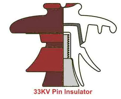
In better voltage systems – like 33kv and 66kv – manufacturing of one element porcelain pin insulator turns into greater difficult. The higher the voltage, the thicker the insulator have to be to offer sufficient insulation. A very thick unmarried piece porcelain insulator isn't realistic to manufacture.
In this example, we use a couple of element pin insulator, in which some well-designed porcelain shells are constant collectively by using Portland cement to shape one complete insulator unit. We commonly use components pin insulators for 33kv, and 3 parts pin insulators for 66kv systems.
Designing consideration of electrical insulator:
The live conductor attached to the pinnacle of the pin insulator which is at the stay ability. We restore the bottom of the insulator to helping shape of earth capacity. The insulator has to resist the capability stresses among conductor and earth. The shortest distance among conductor and earth, surrounding the insulator body, along which electric discharge can also take region thru the air, is known as flashover distance.
When the insulator is moist, its outer floor becomes almost undertaking. For this reason the flashover distance of insulator is reduced. The design of an electrical insulator have to be such that the decrease of flashover distance is minimal when the insulator is wet.
That is why the uppermost petticoat of a pin insulator has umbrella kind designed so that it can shield, the rest lower a part of the insulator from the rain. The top floor of the topmost petticoat is willing as less as possible to maintain most flashover voltage all through raining.
The rain sheds are made in this type of manner that they must now not disturb the voltage distribution.
They're so designed that their subsurface at a proper angle to the electromagnetic lines of pressure.
Post insulator
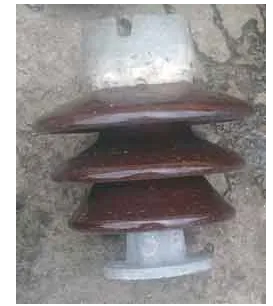
Post insulators are just like pin insulators, however publish insulators are more suitable for higher voltage programs.
Post insulators have a better wide variety of petticoats and a greater height as compared to pin insulators. We will mount this type of insulator on helping structure horizontally in addition to vertically. The insulator is fabricated from one piece of porcelain and it has clamp association are in both pinnacle and backside stop for fixing.
Suspension insulator
In better voltage, past 33kv, it becomes uneconomical to apply pin insulator because length, weight of the insulator become more. Managing and changing larger length single unit insulator are quite hard assignment. For overcoming these problems, suspension insulator became developed.
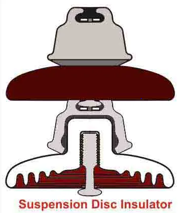
In suspension insulator numbers of insulators are related in series to form a string and the road conductor is carried with the aid of the bottom maximum insulator. Each insulator of a suspension string is known as disc insulator because of their disc like shape.
Strain insulator
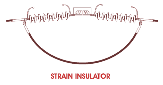
While suspension string is used to sustain excellent tensile load of conductor it is referred as string insulator. Whilst there may be a dead quit or there may be a pointy nook in transmission line, the line has to sustain a tremendous tensile load of conductor or stress. A stress insulator need to have vast mechanical power in addition to the important electrical insulating homes.
Stay insulator

For low voltage strains, the stays are to be insulated from ground at a top. The insulator used inside the live cord is called as the live insulator and is normally of porcelain and is so designed that during case of breakage of the insulator the guy-cord will now not fall to the ground.
Shackle insulator or spool insulator
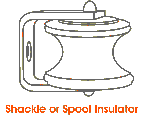
The shackle insulator (also known as a spool insulator) is commonly utilized in low voltage distribution network. It can be used in both the horizontal or vertical positions. The use of such insulator has reduced recently after increasing the using of underground cable for distribution reason.
The tapered hole of the spool insulator distributes the burden more lightly and minimizes the possibility of breakage when heavily loaded. The conductor within the groove of shackle insulator is fixed with the help of smooth binding cord.
The voltage distribution over suspension insulator string. Let, there are 5 nos. Disc insulators which might be connected in series thru steel hyperlink and suspense from line tower that's shown inside the discern. From the determine, it is seen that porcelain portion of every disc is in between metal links.
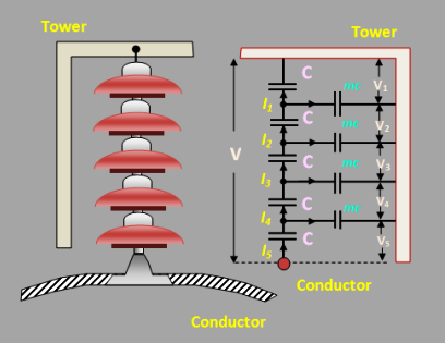
Therefore each disc bureaucracy a capacitor c as shown in fig. It is called mutual capacitance or self-capacitance. And capacitance also exists between steel becoming of every disc and tower or earth. That is called shunt capacitance mc. Because of the shunt capacitance, the charging modern-day is not the identical even though all the disc of string. Consequently, the voltage throughout every disc might be different.
And voltage across to the closest conductor will have the most voltage. The reference to fig. V5 may be a great deal than v4 or v3 or v2 or v1.
The following points can be stated concerning the ability distribution over a string of suspension insulators:
- Because of the presence of shunt capacitor, the voltage throughout the suspension insulators does not distribute itself uniformly throughout the each disc.
- The voltage throughout the closest disc to the conductor is most than others disc.
- The unit nearest to the conductor is under most electric pressure and is in all likelihood to be punctured.
- Inside the case of d.C voltage, the voltage across every unit will be the same. It's miles due to the fact insulator capacitance are useless for d.C.
- Stringing performance:
- The ratio of the voltage throughout the whole string to the fabricated from numbers of discs and the voltage throughout the disc nearest to the conductor is referred to as string efficiency.


String efficiency is crucial for the overhead transmission line. The greater the string efficiency, the extra uniform is the voltage distribution within the each disc insulator. In the right case, the value of string performance might be 100%, but, in an everyday case, it's miles impossible to gain one hundred% string performance, but effort should be made to improve it as close to this value as possible.
Mathematical expression:
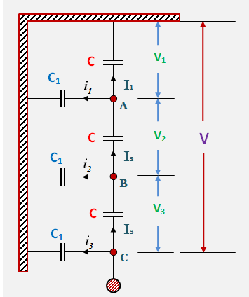
Fig. Indicates the equal circuit for a 3-disc string. Allow us to suppose that self-capacitance of each disc is c1, let us in addition anticipate that shut capacitance c1 is a few fractions okay of self –capacitance i.e., c1 =kc. Starting from the cross –arm or tower, the voltage across unit is v1, v2, v3 respectively as proven.
Applying Kirchhoff’s present-day regulation to node a, we get,
I2 =i1 + i1
Or, v2ωc = v1ωc + v1ωc1
Or, v2ωc = v1ωc + v1ωkc
v2=v1(1+ok) .................(i)
Making use of Kirchhoff’s present-day law to node b, we get,
I3 = i2 + i2
Or v3ωc = v2ωc +(v1+v2) ωc1
Or v3ωc = v2ωc +(v1+v2) ωkc
Or v3=v2+(v1+v2) k
=kv1+v2(1+ok)
=kv1+v1(1+k)2
=v1[K+(1+K)2]
V3=v1[1+3K+K2] .................(ii)
Voltage between conductor and earth (i.e., tower)
V = v1 + v2 + v3
=v1+v1(1+k) +v1(1+3k+k2)
=v1(3+4k+k2)
.................(iii)


Voltage across 2d unit from top, v2 = v1 (1 +okay)
Voltage across third unit from pinnacle, v3= v1(1 +3k + k2)
The subsequent factors can be stated from the above mathematical analysis:
If okay=0.2 (say), then we get, v2 = 1.2 v1, and v3 = 1.64 v1. This genuinely indicates that disc nearest to the conductor has most voltage across it, the voltage across different discs decreasing progressively because the cross arm in approached.
The greater the cost of k, (= c1/c), the more non-uniform is the voltage across the discs and lesser the cost of string efficiency.
The unequally in voltage distribution boom with the growth of numbers of discs. Hence, the shorter string has greater performance than the larger one.
(i) The use of longer cross arms
It's miles clean from the above mathematical expression of string efficiency that the cost of string efficiency relies upon the fee of k. Lesser the fee of okay, the greater is the string performance. Because the fee of ok procedures to 0, the string performance techniques to 100%. The value of k may be reduced through reducing the shunt capacitance. To be able to lower the shunt capacitance, the space between the insulator string and the tower ought to be increased, i.e., Longer pass-hands have to be used. But, there may be a restriction in increasing the length of move-arms due to economic issues.
(ii) Grading of insulator discs
On this method, voltage throughout every disc can be equalized by means of using discs with special capacitances. For equalizing the voltage distribution, the pinnacle unit of the string need to have minimal capacitance, even as the disc nearest to the conductor should have most capacitance. The insulator discs of different dimensions are so selected that the every disc has a specific capacitance. They may be organized in this kind of manner that the capacitance will increase step by step in the direction of the bottom. As voltage is inversely proportional to capacitance, this approach tends to equalize the voltage distribution throughout each disc.
(iii) By the usage of a guard or grading ring
A protect ring or grading ring is essentially a metallic ring which is electrically related to the conductor surrounding the bottom unit of the string insulator. The guard ring introduces capacitance between steel hyperlinks and the line conductor which tends to cancel out the shunt capacitances. As a result, almost equal charging contemporary flows thru every disc and, hence, enhancing the string efficiency. Grading jewelry are from time to time similar to corona earrings, but they encircle insulators instead of conductors.
Mechanical concepts in transmission lines layout need to rely to a point at the significance of continuity of operation inside the line underneath attention. In preferred, the strength of the line have to be together with to offer against the worst likely climate conditions. We now talk some vital points in the mechanical principles in transmission strains.
1.Tower height:
Tower height depends upon the length of span. With long spans, incredibly few towers are required but they should be tall and correspondingly pricey. It isn't usually possible to decide the tower peak and span duration on the premise of direct creation fees because the lightning risks boom greatly because the height of the conductors above ground is multiplied. This is one motive that horizontal spacing is favored in spite of the broader proper of manner required.
2.Conductor clearance to floor:
The conductor clearance to floor at the time of first rate est sag ought to now not be less than a few designated distance (typically among 6 and 12 m), relying on the voltage, on the character of the U.S.A. And at the neighborhood legal guidelines. The finest sag may also arise on the hottest day of summer time because of the expansion of the cord or it may arise in winter due to the formation of a heavy coating of ice at the wires. Unique provisions need to be made for melting ice from the strength traces.
3.Sag and tension:
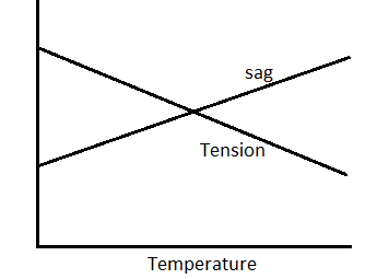
When laying overhead transmission strains, it's far vital to permit an inexpensive component of safety in recognize of the tension to which the conductor is subjected. The anxiety is ruled by way of the effects of wind, ice loading and temperature versions. The relationship among tension and sag is dependent on the loading situations and temperature variations. As an instance, the anxiety increases when the temperature decreases and there is a corresponding lower within the sag. Icing-up of the line and wind loading will purpose stretching of the conductor via a quantity depending on the road anxiety.
In planning the sag, tension and clearance to floor of a given span, a most stress is chosen. It's miles then aimed to have this pressure developed at the worst probable climate conditions (i.e., Minimal predicted temperature, maximum ice loading and maximum wind). Wind loading will increase the sag within the path of resultant loading however decreases the vertical component. Consequently, in clearance calculations, the impact of wind ought to now not be protected unless horizontal clearance is critical.
4)Stringing charts:
For use inside the field paintings of stringing the conductors, temperature-sag and temperature-anxiety charts are plotted for the given conductor and loading situations. Such curves are referred to as stringing charts (see fig. Eight.33). Those charts are very beneficial while stringing overhead strains.
Mechanical principles in transmission lines
5. Conductor spacing:
Spacing of conductors ought to be such with a purpose to provide protection against flash-over when the wires are swinging within the wind. The right spacing is a characteristic of span duration, voltage and climate situations. Using horizontal spacing eliminates the risk due to unequal ice loading. Small wires or wires of light fabric are subjected to more swinging by using the wind than heavy conductors. Therefore, mild wires should be given more spacing.
6.Conductor vibration:
Wind exerts strain on the exposed surface of the conductor. If the wind pace is small, the swinging of conductors is innocent supplied the clearance is adequately big in order that conductors do no longer method inside the sparking distance of every different. A very specific sort of vibration, referred to as dancing, is caused by the movement of pretty sturdy wind on a cord blanketed with ice, when the ice coating occurs to take a shape which makes a very good air-foil phase.
Then the entire span may additionally sail up like a kite until it reaches the restrict of its slack, stops with a jerk and falls or sails lower back. The harmful results of those vibrations occur at the clamps or helps where the conductor suffers fatigue and breaks eventually. On the way to guard the conductors, dampers are used.
The catenary curve is the graph of the hyperbolic cosine feature. The floor of revolution of the catenary curve, the catenoid, is a minimal floor, specifically a minimal floor of revolution. A hanging chain will expect a shape of least potential energy that is a catenary.[4] Galileo Galilei in 1638 mentioned the catenary in the book new sciences spotting that it become one of a kind from a parabola. The mathematical houses of the catenary curve had been studied by means of Robert hooked inside the 1670s, and its equation changed into derived through Leibniz, Huygens and Johann Bernoulli in 1691.
Catenaries and associated curves are utilized in architecture and engineering (e.g., inside the layout of bridges and arches so that forces do now not bring about bending moments). In the offshore oil and gasoline enterprise, "catenary" refers to a steel catenary riser, a pipeline suspended between a manufacturing platform and the seabed that adopts an approximate catenary form. Within the rail industry it refers to the overhead wiring that transfers energy to trains. (this often helps a lighter touch twine, in which case it does not comply with a real catenary curve.)
In optics and electromagnetics, the hyperbolic cosine and sine features are simple answers to maxwell's equations.[5] the symmetric modes along with evanescent waves could form a catenary form.
Calculation of sag and tension in transmission line depend on the span of the conductor. Span having same degree supports is referred to as stage span, while the level of the supports isn't always at an equal level is known as unequal degree span. The calculation of conductor at an identical level shown below.
Don't forget a conductor aob suspended freely among stage helps a and b on the equal level. The bottom point of the conductor is o. Let the form of the conductor be a parabola.
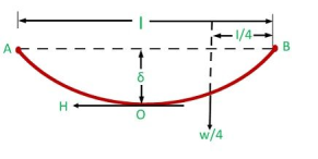
L – span length
W- weight in step with unit duration of the conductor
δ – conductor sag
H – tension in the conductor on the factor of maximum deflection o
Tb – tension within the conductor on the point of aid b.
Take into account ob is the equilibrium tension of the conductor and force appearing on it are the horizontal anxiety h at o. The load (w.Ob) of the conductor ob appearing vertically downwards via the center of gravity at a distance l/four from b, and the tension tb at the assist b.

Sag-and-anxiety-equation-1since ob is about same to the l/2
Take moments approximately b


Sag-and-anxiety-2above equation suggests that the sag in a freely suspended conductor is at once proportional to the weight in line with unit duration of the conductor, and the rectangular of the span period and inversely proportional to the horizontal anxiety h.
Calculation of sag and tension at an unequal level supports:
In hilly areas or sloping grounds, the supports aren't usual on the same degree. For the calculation of sag and tension at unequal helps level do not forget a conductor aob. The portion of oa and ob may be handled as catenaries of half span x and l-x respectively proven within the determine underneath.
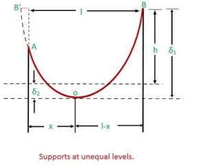
Unequal-stage-helps
Allow,
H – difference span length among a and b
L – horizontal span duration between a and b
X – the horizontal distance of a from the bottom factor o.
L – x – a horizontal distance of b from the bottom factor o.
The sag at oa and ob is expressed by means of the equations


Sag-and-tension-unequal-level-assist-1the tension a and b are given by


Sag-tension-unequal-help-2the maximum anxiety will occur at b on account that (l-x) is more than x as visible within the discern above.
Vertical reaction at the higher assist – w.(l-x)
Vertical reaction at lower support – w.X
For calculation, it's miles assumed that the aob is the parabola.


Sag-tension-unequal-degree-3


But,


Sag-unequal-stage-4sag-and-anxiety-unequal-level-5the value of x acquired above can be substituted in equation (five) to calculate sag at oa. Equation (8) shows that the lowest factor lies outdoor the span ab. As a result, the conductor inside the span beneath attention exert an upward pressure, and the conductor has a tendency to swing clean of the decrease help.
Supports at different levels:
While transmission traces are run on steep inclines, as in case of hilly areas, the two helps a and b might be at special degrees. The form of the conductor strung between the helps can be assumed to be a part of the parabola. In this situation, the bottom point of the conductor will now not lie within the middle of the span.
Keep in mind an overhead line conductor aob, supported over the supports a and b, as illustrated in fig.
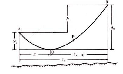
Allow the distinction in ranges between the 2 helps be h and the lowest point o of the conductor be at a distance of x meters from the assist at low stage.
So, distance of o from better stage help = (l – x) meters
From eq. (10.24)
S1 = wx2/2t … (10.26)
And s2 = w (l – x)2/2t … (10.27)
Difference in two ranges of supports,


Or 
Or 
Or 
From the above eqs. (10.26), (10.27) and (10.28) vicinity of factor o and for that reason the values of s1 and s2 can be determined.
Below statutory conditions, the sag is required to be determined for worst likely situations and the minimum floor clearance is to be maintained for these situations. At the time of erection the severe conditions do not be triumphant, the temperature is normally higher, the designer, therefore, must know the sag to be allowed and the tension in the line to be allowed, so that beneath no condition there should be any hazard to the road.
Stringing chart is useful in knowing the sag and anxiety at any temperature. This chart gives the information for sag to be allowed and the tension to be allowed at a selected temperature.
For coaching of stringing or sag chart first of all calculate the sag and anxiety at the conductor below the worst situations i.e. Most wind pressure and minimal temperature, assuming a suitable component of protection in fixing the most working tension for the conductor. Now compare the sag and tension for a chain of temperatures in steps within the operating range of temperatures.
The equation for determining stringing chart of a line is derived as under:
We know that 
 and span length,
Permit w1, f1, l1, s1 and t1 be the burden in step with unit length, the strain, the span duration, sag and temperature at the maximum load situations (with the ice and wind and low temperature typically – 5.Five°); w2, f2, l2, s2 and t2 be the values beneath stringing situations, a is the area of x-segment of the conductor, α is the coefficient of linear growth and e is the modulus of elasticity.
Span length 
The span duration at maximum load situation is:

The temperature rise from t1 to t2 reasons a boom within the span period of l1α (t2 – t1) that's almost same to l1α (t2 – t1). The autumn in strain from f1 to f2 causes a lower inside the period of

The brand new duration l2 is for that reason given by way of:

But 


Equation is a cubic equation and can be solved graphically or analytically. From this equation erection tension t1 = f1a can be decided such that anxiety t2 – f2a under worst probably situations will not exceed the secure limit of hysteria.
After figuring out f2, the corresponding sag can be decided from the equation:

Diverse values of f2 and s2 are calculated the usage of eqs. (10.39) and (10.40) again and again for distinct temperatures. Now the graph of hysteria vs temperature and sag vs temperature may be plotted, as shown in fig. 10.19. This graph is plotted for a fixed span and is known as the stringing chart. The stringing chart may be very beneficial at the same time as erecting the transmission line conductors for adjusting the sag and tension properly.
In the preliminary making plans degrees, a survey of the proposed course enables an envisioned line profile to be drawn, as illustrated in fig. (a). Such a profile is constructed with the horizontal scale a whole lot greater decreased (say to 1/10) in comparison to vertical scale. This profile ought to meet the minimal clearance necessities, and the region of the helps ought to be such that some horizontal adjustment is possible without departing from the same old or tangent tower lengths.
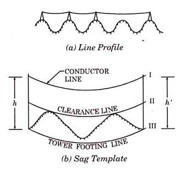
Use is made from sag templates attracted to the equal scale as the line profile, to make sure the required clearance. The sag template is generally made on celluloid or tracing fabric. In sag template, proven in fig. (b), the upper curve i represent the conductor line. The center curve (i.e., Curve ii) is below the upper curve i by way of a uniform vertical distance same to the preferred minimal vertical clearance to floor.
This clearance to ground is ruled by using the running voltage and is given, in step with ie policies, in desk 10.2. The lower curve (curve iii) is under the upper curve by means of a uniform vertical distance same to the peak of a trendy tower measured to the factor of help of the conductor.
If the region of the left tower has been determined, the place of the right-hand tower can be decided through adjusting the sag template so that the conductor line passes via the point of aid at the left-hand tower and the clearance line is tangent to ground at one or more factors.
Inside the above specific case, illustrated the points of conductor support are upon the equal horizontal degree, but the identical manner applies when the route is a steeply sloping one. However, the form and position of the conductor will continually be represented via curve i, as proven in fig. (b).
Sag template may be very a handy method for allocating the positions and peak of the towers/helps successfully at the profile.
It may no longer be possible to have a segment of transmission line such as successive spans of same lengths because the location of the towers relies upon the profile of land along which the transmission line is to be laid. Every so often additionally, the towers are forced to be placed to provide spans of different lengths so that minimum interference is precipitated with using land. When the successive spans are of unequal lengths modifications in anxiety in load or temperature will cause unequal adjustments in tension inside the specific spans.
It's far very tedious to make calculations of sag and anxiety for each and each span individually and then to make adjustment at the same time as erecting the transmission line. Inside the erection of a transmission line the conductors are run out through clutch blocks attached to the assist hands equally tensioned at each end of a section of five or six blocks. When the conductors are clamped to suspension insulator strings, the equal tension is maintained through insulator swing. When the conductors are sure to pin-kind insulators, the ability of the helps ensures identical anxiety.
It's miles regularly handy to make sag and anxiety calculations in phrases of a hypothetical equal span, this tension being carried out to every span within the phase of overhead line among the tensioning factors. If there are n spans of duration l1, l2, l3, and so forth. Which are to accept an equivalent span le, then the strung length of the equivalent line should be the same as that of the individual spans.
This can be expressed as:


So

If the road tension t0 is decided for the equivalent span, the sag for the man or woman spans can be calculated from eqs. (10.17) the usage of the approximate cost of span.
It's far to be stated that the technique of sag template for finding the towers must not be used for lengthy spans as well as in which the slope of the profile may be very steep. In such instances, actual calculations for sag and anxiety need to be made.
Conductor stringing systems currently employed in the energy industry are nearly as numerous because the companies that string conductors. Below is an outline of the primary strategies currently in use, but they are continuously changed to house equipment with ease to be had and the ideas and philosophies of the responsible supervisors.
Further to an outline of the diverse techniques getting used are comments relative to utility and a listing of device relevant to each method.
Slack or layout method
Using this approach, the conductor is dragged along the floor by means of a pulling automobile, or the reel is carried along the road on a car and the conductor is deposited at the floor. The conductor reels are positioned on reel stands or jack either placed at the floor or mounted on a transporting car.
These stands are designed to guide the reel on an arbor, therefore permitting it to turn because the conductor is pulled out. Generally, a braking tool is provided to prevent overrunning and backlash. When the conductor is dragged past a helping shape, pulling is stopped and the conductor is located in vacationers attached to the structure earlier than intending to the next structure.
This approach is mainly relevant to the construction of new lines in cases in which renovation of conductor floor circumstance isn't vital and where terrain is effortlessly handy to a pulling car. The approach is not normally economically relevant in urban places wherein hazards exist from visitors or wherein there may be hazard of touch with energized circuits, nor is it realistic in mountainous regions inaccessible to pulling cars.
Major system required to perform slack stringing consists of reel stands, pulling automobile(s), and a splicing cart.
Tension method:
The use of this method, the conductor is stored beneath tension throughout the stringing process. Generally, this approach is used to preserve the conductor clear of the floor and barriers, which might motive conductor surface harm, and clear of energized circuits.
It calls for the pulling of a mild pilot line into the tourists, which in turn is used to pull in a heavier pulling line. The pulling line is then used to pull within the conductors from the reel stands using mainly designed tensioners and pullers.
For lighter conductors, a light-weight pulling line can be utilized in vicinity of the pilot line to without delay pull within the conductor. A helicopter or floor vehicle can be used to drag or lay out a pilot line or pulling line.
The anxiety technique of stringing is applicable wherein it's miles desired to keep the conductor off the ground to reduce surface harm or in regions where common crossings are encountered. The quantity of proper-of-way travel with the aid of heavy gadget is likewise decreased.
Generally, this technique gives the most comparatively cheap means of stringing conductor. The helicopter use is particularly nice in rugged or poorly available terrain.
Major device required for tension stringing consists of reel stands, tensioner, puller, reel winder, pilot line winder, splicing cart, and helicopter or pulling vehicle.
The overhead transmission line stories vibrations inside the vertical aircraft and there are two kinds of such vibrations, in addition to normal swinging in wind, referred to as the aeoline vibrations or resonant vibrations or excessive frequency oscillations and galloping or dancing or low frequency vibrations.
Simple swinging of conductors is harmless furnished the clearance is satisfactorily huge in order that the conductors do now not method inside the sparking distance of every other.
Aeoline vibrations are excessive frequency (five-100 hz) and coffee amplitude (20 mm to 50 mm) vibrations. They are resulting from vortex phenomenon in mild winds (five-20 km/hour). The road conductor vibrates in some of loops.
The duration of the loop (1/2-wave period) relies upon on tension t and weight of conductor w per metre duration and is given by means of. The loop duration varies from 1 to ten meters relying upon t, w and f. Those vibrations are common to all conductors and are greater or much less usually present. The harmful results of such vibrations take place at clamps or supports wherein the conductor suffers fatigue and breaks subsequently.
Low frequency vibrations (approximately one Hz) occur at some point of sleet storms with a sturdy wind. The amplitude could be very massive, approximately 6 meters or extra, and the conductors are stated to ‘dance’. Operation is sort of not possible for the conductors contact one another, for the reason that ‘dancing’ takes place horizontally and vertically.
It is taken into consideration that the phenomenon takes area because of the truth that the line conductor receives an abnormal coating of sleet. If the cross-phase of the coating is considered to be an ellipse, the road will revel in a drag; furthermore, if the essential axis of an ellipse makes an attitude of 45° to the wind, there will be a sizable aerodynamic elevate (or downward thrust) such as is experienced by way of an aerofoil.
The conductor will as a consequence dance horizontally and vertically with big amplitude and in an abnormal way thanks to the abnormal deposition of sleet. The stranding of conductors also contributes to those vibrations. The tour of conductor follows the path of an ellipse. There is no method for prevention of these (low-frequency) vibrations. But, hazard due to such vibrations may be decreased if horizontal conductor configuration is used.
The conductors are covered via dampers which save you the resonant vibrations from attaining the conductors on the clamps or helps.
The inventory bridge damper, includes two weights connected to a chunk of stranded cable 0.Three or 0.Five m lengthy, which is clamped to the road conductor. The power of vibration is absorbed with the aid of the stranded cable, and the vibration is rapidly damped out.
Every other successful damper includes a box containing a weight resting on a spring. In this case the spring absorbs the electricity of vibration. The fatigue can be reduced through reinforcing the conductor for a few meters on both facet of the clamp by binding metal rods or a period of the same conductor to the main conductor outside the clamp.
References:
[1] J. Grainger and W. D. Stevenson, “Power System Analysis”, McGraw Hill Education,
1994.
[2] O. I. Elgerd, “Electric Energy Systems Theory”, McGraw Hill Education, 1995.
[3] D. P. Kothari and I. J. Nagrath, “Modern Power System Analysis”, McGraw Hill
Education, 4th Edition, 2011.
[4] B. M. Weedy, B. J. Cory, N. Jenkins, J. Ekanayake and G. Strbac, “Electric Power
Systems”, Wiley, 5th Edition, 2012.
[5] C.L. Wadhwa, “Electrical Power Systems”, New Age International Publishers, 6th
Edition.
[6] A. R. Bergen and V. Vittal, “Power System Analysis”, Pearson Education Inc, 1999.