Unit - 4
Method of Symmetrical Component
Symmetrical components:
Symmetrical components are nothing but a mathematical modeling which is used to analysis the unbalanced three phase power machine each normal and ordinary situation.
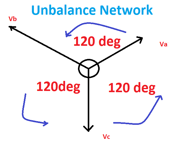
In three phase gadget, the symmetrical additives are referring 3 distinctive unbalance phasors are
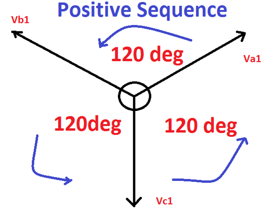
Positive sequence:
A balanced three-phase machine with the same section series as the authentic series. To say tremendous sequence additives which must have 3 vectors of equal magnitude but displaced in section from every different by an perspective of a hundred and twenty° and have the section collection identical because the authentic vectors. Phase sequence means the direction of rotation of vectors.
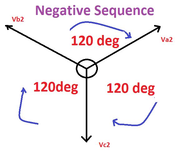
Negative sequence:
A balanced 3-phase device with the opposite phase collection as the unique collection because of this the set of the 3 phasors are identical in significance, spaced one hundred twenty° apart from each other and having the phase sequence contrary to that of the original phasors.
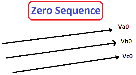
Zero sequence:
Three phasors that are equal in importance and section.
Analyze extra: touch multiplier relay operating feature & wiring diagram
Sequence notations:
In this the original set of 3 phasors are denoted by means of va , vb and vc , even as their positive, terrible and zero series additives are denoted with the aid of the subscripts 1, 2 and 0 respectively. Meaning the fine, terrible and zero collection components of section-a is denoted by using va1 (fine series), va2 (bad series) and va0 (zero collection) respectively.
Electrical fault:
An electrical fault is the deviation of voltages and currents from nominal values or states. Below normal running situations, power device system or traces bring regular voltages and currents which ends up in safer operation of the device.
But when a fault occurs, it reasons excessively high currents to flow which causes harm to system and gadgets. Fault detection and analysis are important to pick out or layout appropriate switchgear gadget, electromechanical relays, circuit breakers, and different protection gadgets.
Types of faults in electrical energy systems:
In the electric power system, the faults are in particular types like open circuit faults and brief circuit faults. And further, those styles of faults can be categorised into symmetrical and unsymmetrical. Let us discuss these sorts of faults in element. These faults are classified into two sorts.
- Symmetrical fault
- Unsymmetrical fault
Symmetrical faults:
Those are very severe faults and arise infrequently in the power systems. Those are also called balanced faults and are of two kinds specifically line to line to ground (l-l-l-g) and line to line (l-l-l).
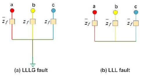
Best 2-five percent of system faults are symmetrical faults. If these faults arise, the machine remains balanced however consequences in excessive harm to the electrical electricity machine system.
The above determine indicates two styles of three-phase symmetrical faults. Analysis of this fault is simple and typically carried on a phased basis. 3-section fault evaluation or records is required for selecting set-phase relays, rupturing capacity of the circuit breakers, and rating of the protective switchgear.
The symmetrical faults are categorized into two sorts
- Line – line – line fault
- Line – line – floor fault
L – l – l fault:
Those varieties of faults are balanced this means that the system stays balanced after the fault happens. So this fault not often occurs, although it is the cruel form of fault that holds the largest cutting-edge. So this modern is used to decide the score of the cb.
L – l – l – g fault:
The 3-phase l – g fault specifically contains all of the three- phase of the device. This fault specially happens many of the 3-stages as well as the ground terminal of the machine. So, there may be a 2 to 3% of opportunity to arise the fault.
Unsymmetrical faults:
Those are very common and much less excessive than symmetrical faults. There are especially three kinds specifically line to floor (l-g), line to line (l-l), and double line to ground (ll-g) faults.
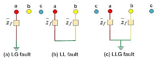
The road to ground fault (l-g) is the most not unusual fault and sixty five-70 percent of faults are of this kind.
It reasons the conductor to make touch with the earth or ground. 15 to 20 percent of faults are double line to ground and reasons the 2 conductors to make contact with the floor. The line to line faults occurs whilst conductors make touch with each different mainly even as swinging of traces due to winds and 5- 10 percentage of the faults are of this type.
These also are referred to as unbalanced faults seeing that their occurrence reasons unbalance in the machine. The unbalance of the machine manner that that impedance values are distinctive in every phase causing unbalance cutting-edge to waft in the phases. These are greater difficult to investigate and are carried by way of in line with phase foundation similar to three-section balanced faults.
The unsymmetrical faults are classified into kinds
- Single l – g (line-to-floor) fault
- L – l (line-to-line) fault
- Double l – g (line-to-ground) fault
Single l – g fault
This single l – g fault specifically occurs once a single conductor falls closer to the ground terminal. So round 70 to 80 % of the fault within the power machine is the single l – g fault.
L – l fault
This l– l fault particularly takes place once two conductors are short-circuited and additionally due to heavy wind. So the road conductors can be moved due to heavy wind, they will contact with every other and reasons short-circuit. So, 15 – 20% of the faults can occur approximately.
Double l – g fault
On this form of fault, both the two lines get in touch with each other thru the ground. So, there may be a ten% opportunity for faults.
Open circuit faults
The open-circuit faults mainly arise because of the malfunction of 1 otherwise extra conductors used inside the power device. The open-circuit faults diagram is proven beneath. This circuit is for 1-phase, 2- levels, and three-stages open circumstance.
These faults specially occur because of commonplace issues like failure of joints in overhead lines, cables, failure inside the phase of a circuit breaker, melting of conductor or fuse within one phase or greater stages.
Those faults are also referred to as series faults which are unbalanced types otherwise unsymmetrical sorts aside from three-section open fault.
For example, a transmission line works thru a balanced load earlier than an open fault circuit occurs. In the transmission line, if any individual of the stages gets dissolved then an alternator’s real loading can be reduced & will increase the acceleration of the alternator, so it really works at a velocity particularly higher than the synchronous speed. In different transmission cables, this over pace can cause overvoltage’s. Consequently, 1-section & 2-section open situations can generate currents and voltages of the power device that reasons large harm to the equipment.
These faults are labeled into 3 types like following.
- Open conductor fault
- Conductors open fault
- 3 conductors open fault.
Causes and outcomes of varieties of faults:
These faults can be brought about because of the circuit malfunctioning as well as broken conductor in 1- section or extra stages. The results of open circuit faults include the subsequent.
Electrical electricity machine irregular operation
- Those faults may additionally risk to animals in addition to human beings
- In particular, a portion of the community, while the voltage is surpassed past ordinary values then it causes insulation failures and develops short circuit faults.
- Despite the fact that, those styles of circuit faults may be frequent for a long time as compared with short circuit type faults, because those faults have to be detached to lower the excessive damage.
Short circuit faults
Short circuit faults especially occur due to failure inside insulation among section conductors and earth. An insulation failure can reason a brief-circuit course formation that activates brief-circuit conditions within the circuit.
The definition of a brief circuit is, an peculiar connection of extremely much less impedance amongst two factors of varied potential, whether or not finished by means of risk or purposely. These faults are the most common kinds which result in the abnormal excessive present day waft throughout the transmission strains or system.
If short circuit faults are allowed to hold even for a small-time, then it ends in extensive damage to the equipment. Brief circuit faults are also called shunt faults due to the fact these faults in particular occur because of the failure in insulation amongst phase conductors in any other case among phase conductors and earth
The distinctive plausible short circuit fault conditions specially comprise three-levels to earth, three-phase clear of the earth, 1- phase to earth, phase to section, 2- phase to earth, phase to section and single-section to earth.
Each the three-section fault clean of the earth, as well as the 3-phase fault closer to earth, can be symmetrical or balanced while other faults are unsymmetrical faults.
Reasons and results of brief circuit faults
The quick circuit faults may occur due to the following motives.
These faults can also arise because of the inner otherwise external results
Inner outcomes are transmission strains breakdown, gadget damage, insulation growing old, corrosion of insulation within the generator, unsuitable installations of electrical gadgets, transformers, and their insufficient design.
These faults may be passed off because of out of doors results of kit, insulation failure due to lighting fixtures surges & mechanical damage by using the general public.
The consequences of quick circuit faults encompass the following.
Arcing faults can motive fireplace & blast in apparatus like transformers as well as circuit breakers.
The flow of power may be restricted significantly otherwise even absolutely blocked if the quick circuit mistakes persists.
The gadget working voltages can pass above or underneath their reputation values to make a harmful impact at the service supplied via the power machine.
Because of atypical currents, the apparatus gets heated in order that the existence span in their insulation can be reduced.
Causes of types of faults
The main motives to reason electric faults encompass the following.
Climate conditions
It includes lights strikes, heavy rains, heavy winds, salt deposition on overhead lines and conductors, snow and ice accumulation on transmission strains, etc. Those environmental conditions interrupt the power deliver and additionally harm electrical installations.
Equipment failures
Numerous electrical system like generators, cars, transformers, reactors, switching gadgets, and many others causes quick circuit faults due to malfunctioning, growing old, insulation failure of cables, and winding. These failures result in excessive current to glide thru the gadgets or gadget which in addition damages it.
Human errors
Electric faults also are prompted because of human mistakes such as choosing wrong rating of gadget or gadgets, forgetting steel or electrical undertaking elements after servicing or renovation, switching the circuit whilst it's far underneath servicing, and many others.
Smoke of fires
Ionization of air, because of smoke particles, surrounding the overhead traces effects in spark between the lines or between conductors to the insulator. This flashover reasons insulators to lose their insulating ability because of high voltages.
A complete diagram of energy device representing all the 3 stages turns into too complex and cumbersome for a gadget of realistic length, so much in order that it may now not convey the facts it's miles meant to bring. It's miles an awful lot greater sensible to symbolize a strength device by way of easy symbols for every component resulting in what is known as a single line diagram.
Single line diagram of an electricity machine:
The single line diagram of an energy system community shows the primary connections and arrangements of the system additives in conjunction with their facts (along with output rating, voltage, resistance and reactance and so forth.). In case of transmission lines once in a while the conductor size and spacings are given.
It isn't always essential to reveal all the components of the system on a single line diagram, e.g., circuit breakers want no longer be proven in a load glide examine however are ought to for a protection have a look at. In a single line diagram, the machine components are usually drawn in the form of their symbols.
Generators and transformer connections—superstar; delta and neutral earthling are indicated with the aid of symbols drawn by the side of the illustration of these elements. Circuit breakers are represented by square blocks. Fig. 2.7 represents the single line diagram of a regular electricity gadget.
The ratings of generator, motor and transformers are given within the diagram underneath:
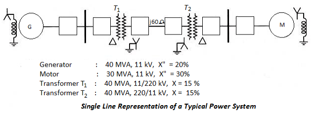
Single line representation of traditional energy device
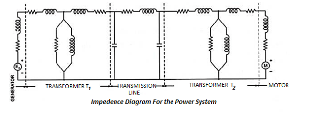
Impedance diagram illustration of a electricity device:
A in addition simplification from the single line diagram, with its symbols for the various additives, is to draw the diagram with impedances most effective.
The impedance diagram of the power device is proven in fig:
Impedance diagram for the power machine
In impedance diagram, every factor is represented by using its equivalent circuit, e.G., the synchronous generator at the generating station through a voltage supply in collection with a resistance and reactance, the transformer through its equal circuit and the transmission line by nominal π-equivalent circuit. Loads are assumed to be passive (no longer concerning rotating machines) and are represented with the aid of resistance and inductive reactance in collection. Neutral earthling impedances do now not seem in the diagram as balanced situations are assumed.
The impedance diagram shown in fig. 2.8 is known as positive sequence diagram due to the fact it is drawn for a balanced 3-phase device. Nonetheless any other opportunity would be to use 3 separate diagrams to symbolize the superb, negative and 0 sequence networks one by one. These three separate impedance diagrams are utilized in short circuit studies of unsymmetrical faults.
Reactance diagram representation of a power device:
The impedance diagram can similarly be simplified through making positive assumptions and decreased to simplified reactance diagram. Reactance diagram is drawn by way of neglecting effective resistance of generator armature, transformer winding resistance, transmission line resistance, line charging and the magnetizing circuit of transformers.
Reactance diagram of strength device is shown in fig:
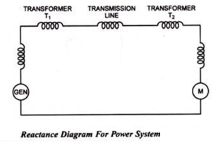
Reactance diagram for power gadget
Assumptions made for drawing reactance diagram deliver outcomes quite accurate for many power gadget studies, which includes short circuit research etc., as winding resistances inclusive of the line resistances are quite small in comparison with leakage reactance and shunt course which incorporates line charging and transformer magnetizing circuit offer a very excessive parallel impedance with fault.
In preferred it's far to be stated that if the resistance is less than one-third of the reactance, and resistance is omitted, the mistake added will now not be greater than five%. If, but, the resistance is of the order of 1-half of that of reactance and resistance is overlooked mistakes up to 12% can be introduced. With the aid of “errors” it is supposed that calculations will bring about values higher than is genuinely the case being acquired and in a few instances, lead to the purchase of protective equipment with a higher rating than required.
Sequence networks of power systems are very useful for computing unsymmetrical faults at special factors of a strength gadget network. The information of positive- sequence community is vital for load-studies on power systems. If the stability research involve unsymmetrical faults, then bad- and 0-sequence networks are required also.
A energy machine community includes synchronous machines, transformers and lines. The use of these, complete series networks of a power gadget may be without difficulty drawn. The high-quality-series network is drawn through inspecting one line diagram of the electricity gadget. In reality, the single line reactance diagram, as employed for calculation of symmetrical fault cutting-edge, is the tremendous-collection diagram of the power device.
The poor-collection community is pretty just like fantastic-sequence community—best turbines or rotating machines may additionally have one-of-a-kind sequence impedances and the bad-sequence community does now not include any voltage supply. The bad-collection impedances for transmission traces and transformers are similar to the high quality-sequence impedances.
In lots of cases only one collection network is drawn for tremendous- and negative-series representation. The reference bus for positive- and poor-series networks is the machine impartial. Any impedance connected among a impartial and floor isn't blanketed in the fantastic- and poor-series networks as neither of these series currents can glide through such an impedance.
0-sequence sub-networks for specific factors of a strength device can be easily mixed to form entire 0-series network. The zero-series community does not include any voltage supply. Any impedance blanketed in generator or transformer neutral will become 3 times its cost in a 0-series community. Special care needs to be taken in connecting the zero-collection impedance of transformer.
All of the collection impedances are expressed in in keeping with-unit values and cited the identical base mva and base kv.
The system for drawing sequence networks is illustrated through the subsequent example:
Example:
Draw the series networks for the energy gadget proven in fig. Three.18:
Energy machine network
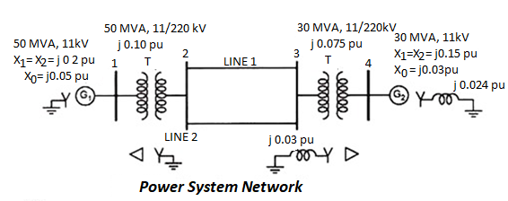
Solution:
Let base mva for entire device be 50 mva, base kv for generator facet 11 kv and transmission side 220 kv.
In line with unit reactances of generator g1 –
X1 = x2 = j zero.2 pu
And x0 = j zero.05 pu …(given)
In line with unit reactances of generator g2 –
X1 = x2 = [j 0.15 x (50/30)] = j zero.25 pu
And x0 = [j 0.03 x (50/30)] = j 0.05 pu
Per unit reactances of transformer t1 –
X1 = x2 = x0 = j zero.10 pu
According to unit reactances of transformer t2 –
X1 = x2 = x0 = [j 0.075 x (50/30)] = j 0. One hundred twenty five pu
In keeping with unit reactances of transmission line 1 –
X1 = x2 = 0.1 pu …(given)
Assuming 0-collection reactance of transmission line three.5 times of its superb-collection reactance –
X0 = zero.35 pu
Per unit reactances of transmission line 2 –
X1 = x2 = j 0.12 pu (given)
X0 = j 0.12 x 3.5 = j 0.42 pu
The neural reactance of j zero.024 and j zero.03 comes out to be [j 0.024 x 950/30)] i.E., zero.Four pu and [j 0.03 x (50/30)] i.E., j zero.05 pu.
These neutral reactances seem as 3 x j zero.04 i.E., j 0.12 pu and three x j 0.05 i.E., j zero.15 pu inside the zero sequence networks.
The advantageous-, negative- and- zero sequence networks are shown in figs. 3.19 (a), three.19 (b) and three.19 (c) respectively:
High quality-, poor- and zero collection networks
Before making use of proper electrical protection system, it's miles necessary to have via understanding of the situations of electrical electricity gadget at some point of faults. The knowledge of electrical fault circumstance is needed to set up proper extraordinary defensive relays in one of a kind places of electrical strength gadget.
Facts regarding values of maximum and minimum fault currents, voltages underneath the ones faults in significance and phase relation with respect to the currents at distinctive parts of power device, to be gathered for correct software of protection relay device in the ones different components of the electric strength device. Accumulating the records from exceptional parameters of the system is commonly called electrical fault calculation.
Fault calculation widely approach calculation of fault cutting-edge in any electric power gadget. There are mainly three steps for calculating faults in a device.
Desire of impedance rotations.
- Reduction of complex electric electricity gadget network to single equivalent impedance.
- Electrical fault currents and voltages calculation by way of the usage of symmetrical aspect theory.
- Impedance notation of electrical electricity gadget
Impedance notation of electrical electricity gadget
If we take a look at any electrical electricity gadget, we are able to find, those are several voltage tiers. As an example, think a standard energy system wherein electric electricity is generated at 6.6 kv then that 132 kv electricity is transmitted to terminal substation where it is stepped all the way down to 33 kv and eleven kv ranges and this 11 kv stage may also similarly step down to 0.Four kv.
Therefore, from this example it's far clean that a equal energy gadget community can also have distinct voltage degrees. So calculation of fault at any place of the stated system becomes a good deal difficult and complicated it attempt to calculate impedance of various components of the device consistent with their voltage stage.
This difficulty may be avoided if we calculate impedance of different a part of the machine in reference to a single base price. This method is known as impedance notation of energy system. In different wards, before electrical fault calculation, the gadget parameters, need to be stated base portions and represented as uniform device of impedance in either ohmic, percentage, or per unit values.
Electric energy and voltage are commonly taken as base portions. In three section system, 3 phase energy in mva or kva is taken as base energy and line to line voltage in kv is taken as base voltage. The base impedance of the gadget can be calculated from those base energy and base voltage, as follows,

Per unit is an impedance cost of any machine is nothing but the radio of actual impedance of the device to the bottom impedance value.

Percent impedance price can be calculated via multiplying one hundred with consistent with unit value.

Again it is from time to time required to transform in keeping with unit values noted new base values for simplifying extraordinary electric fault calculations. In that case,

The selection of impedance notation relies upon upon the complicity of the system. Generally base voltage of a gadget is so selected that it calls for minimal range of transfers.
Assume, one system as a big wide variety of 132 kv over head strains, few numbers of 33 kv strains and only a few variety of eleven kv lines. The base voltage of the gadget may be chosen either as 132 kv or 33 kv or 11 kv, but right here the first-class base voltages 132 kv, as it calls for minimum quantity of transfer all through fault calculation.
- Network reduction
After choosing the perfect impedance notation, the following step is to reduce community to a single impedance. For this primary we have to convert the impedance of all turbines, traces, cables, transformer to a common base fee. Then we prepare a schematic diagram of electrical electricity system displaying the impedance cited identical base price of all those turbines, strains, cables and transformers.
The network then decreased to a common equal single impedance by using using famous person/delta transformations. Separate impedance diagrams need to be organized for high-quality, negative and 0 sequence networks.
There phase faults are precise on account that they are balanced i.E. Symmetrical in 3 phase, and can be calculated from the single phase nice series impedance diagram. Therefore three phase fault cutting-edge is received by way of,
Wherein, i f is the total three section fault contemporary, v is the section to neutral voltage z 1 is the full high-quality series impedance of the machine; assuming that in the calculation, impedance are represented in ohms on a voltage base.
- Symmetrical component analysis
The above fault calculation is made on assumption of three section balanced system. The calculation is made for one phase handiest because the current and voltage situations are equal in all three stages.
Whilst real faults arise in electrical power machine, which include phase to earth fault, phase to phase fault and double phase to earth fault, the device becomes unbalanced approach, the situations of voltages and currents in all levels are now not symmetrical. Such faults are solved with the aid of symmetrical element analysis.
Generally 3 section vector diagram can be changed by way of three units of balanced vectors. One has contrary or bad section rotation, 2nd has effective phase rotation and remaining one is co-phasal. Meaning those vectors sets are defined as positive negative and zero sequence, respectively.
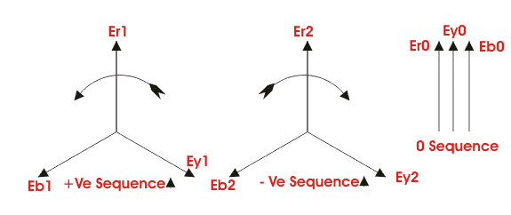
The equation among phase and series quantities are,


Therefore,


In which all quantities are referred to the reference phase r.
Similarly a hard and fast of equations may be written for collection currents also. From, voltage and contemporary equations, one could easily decide the sequence impedance of the device.
The development of symmetrical component analysis depends upon the truth that in balanced device of impedance, collection currents can provide upward push only to voltage drops of the identical collection. As soon as the collection networks are to be had, those can be transformed to single equal impedance.
Allow us to take into account z1, z2 and z0 are the impedance of the gadget to the float of effective, bad and 0 series contemporary respectively.
For earth fault

Phase to phase faults


Double phase to earth faults


3 phase faults

If fault current in any precise branch of the community is needed, the equal can be calculated after combining the series components flowing in that branch. This involves the distribution of collection components currents as decided with the aid of solving the above equations, of their respective community consistent with their relative impedance. Voltages it any point of the community also can be determine once the collection factor currents and series impedance of each department are recognised.
Series impedance
Positive sequence impedance
The impedance provided via the gadget to the go with the flow of high-quality collection modern is known as tremendous collection impedance.
Negative sequence impedance
The impedance supplied by using the gadget to the waft of poor collection cutting-edge is called poor series impedance.
Zero sequence impedance
The impedance offered by using the device to the drift of zero collection current is referred to as zero sequence impedance.
In preceding fault calculation, z1, z2 and z0 are wonderful, poor and 0 collection impedance respectively. The collection impedance varies with the form of strength system components under consideration:-
In static and balanced strength device additives like transformer and lines, the collection impedance supplied by means of the device are the same for effective and terrible sequence currents. In different words, the tremendous sequence impedance and bad collection impedance are equal for transformers and electricity lines.
However in case of rotating machines the superb and bad series impedance are extraordinary.
The challenge of zero sequence impedance values is a more complex one. That is because the three zero series current at any factor in a electrical electricity system, being in phase, do not sum to 0 however must return via the neutral and /or earth.
In 3 section transformer and system fluxes because of 0 series additives do now not sum to 0 in the yoke or discipline gadget. The impedance very broadly depending upon the physical arrangement of the magnetic circuits and winding.
The reactance of transmission lines of 0 series currents can be about three to 5 instances the wonderful series current, the lighter cost being for lines without earth wires.
This is because the spacing between the go and return(i.E. Neutral and/or earth) is so much greater than for tremendous and bad sequence currents which return (balance) within the 3 phase conductor agencies.
The 0 collection reactance of a device is compounded of leakage and winding reactance, and a small aspect because of winding balance (relies upon on winding tritch).
The zero series reactance of transformers depends each on winding connections and upon the development of the center.
In neutral grounding device, the neutral of the gadget or rotating device or transformer is connected to the ground. The impartial grounding is an essential factor of energy system layout because the performance of the gadget regarding quick circuits, stability, protection, and many others., is substantially suffering from the circumstance of the impartial. A 3 segment gadget can be operated in two possible ways
- With ungrounded neutral
- With a grounded impartial
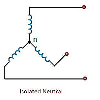
Ungrounded neutral machine
In an ungrounded neutral machine, the impartial isn't connected to the grounded. In other words, the neutral is isolated from the ground. Therefore, this machine is likewise regarded the remoted neutral machine or unfastened impartial machine proven in the figure beneath.
Grounded system:
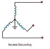
In impartial grounding system, the neutral of the machine is attached to the floor. Because of the troubles related to ungrounded neutral systems, the neutrals are grounded in most of the excessive-voltage systems.
Some of the advantages of impartial grounding are as follows
- Voltages of stages are constrained to the line-to-ground voltages.
- Surge voltage due to arcing grounds is removed.
- The overvoltage’s because of lightning discharged to ground.
- It affords more safety to employees and device.
- It affords progressed service reliability.
Methods of neutral grounding:
The methods commonly used for grounding the device impartial are
- Stable grounding (or powerful grounding)
- Resistance grounding
- Reactance grounding
- Peterson-coil grounding (or resonant groundings)
The selection of the form of grounding relies upon on the size of the unit, gadget voltage and safety scheme to be used.
References:
[1] J. Grainger and W. D. Stevenson, “Power System Analysis”, McGraw Hill Education,
1994.
[2] O. I. Elgerd, “Electric Energy Systems Theory”, McGraw Hill Education, 1995.
[3] D. P. Kothari and I. J. Nagrath, “Modern Power System Analysis”, McGraw Hill
Education, 4th Edition, 2011.
[4] B. M. Weedy, B. J. Cory, N. Jenkins, J. Ekanayake and G. Strbac, “Electric Power
Systems”, Wiley, 5th Edition, 2012.
[5] C.L. Wadhwa, “Electrical Power Systems”, New Age International Publishers, 6th
Edition.
[6] A. R. Bergen and V. Vittal, “Power System Analysis”, Pearson Education Inc, 1999.