Module 03
Operational Amplifiers
Schematic Symbol
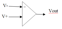
V+ : voltage at inverting input
V- : voltage at non-inverting input
A : voltage gain of op-amp
Characteristics of ideal op-amp
An ideal op-amp is a differential input, single output device.
It has the following characteristics:
Inverting Amplifier
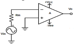
Fig : inverting op-amp (Ref: 1)
V1 = 0V and V2 = Vin
- Vout = A( - Vin )
- where, A is the voltage gain of op-amp.
Non-Inverting Amplifier
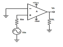
Fig : Non inverting amplifier (Ref: 1)
V1 = Vin and V2 = 0V
Vout = AVin
where, A is the voltage gain of op-amp.
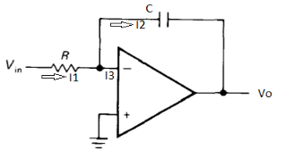
Fig: Integrator

Ignoring I3 we have, I3 ≈ 0
So, I1 ≈ I2.


However, V = 0 because gain A is very large

Integrating both sides we get


 + Q
+ Q
Where Q is the integration constant and is proportional to Vo at t = 0 sec .
Therefore, voltage Vo is directly proportional to Vin and inversely proportional to constant RC.
Frequency response of basic integrator circuit is given by,
 ( for 0 db gain)
Differentiator
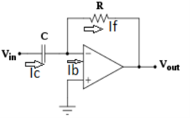
Fig. : Differentiator

Since Ib = 0 then,
Ic ≈ If

Since Gain A is very large hence, V1 = 0

Or 
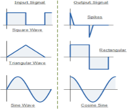
Fig.: Input and output waveform of differentiator (Ref. 1)
 ( for 0 db gain)
Summing Amplifier
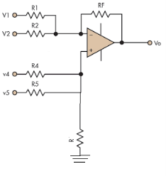
Fig. : Summing amplifier (Ref: 1)


Hence,


Similarly,

So, the resultant output voltage by all the 4 input voltages is given by,
Vo = V01 + V02 + V04 +V05
Vo = -V1 – V2 +V4 + V5
The output voltage Vo is equivalent to the sum all input voltages applied at both the terminals.
Numerical 1:
In a summing amplifier, if R = 1kΩ, Va = +3V, Vb = +8V, Vc = +9V, Vd = +5V and supply voltage is ±15V. Find the output voltage Vo.
Solution:
Vo = Sum of all input voltages applied at both the terminals
Vo = Va + Vb + Vc +Vd
Vo = -3 -8 +9 +5
Vo = +3V
Numerical 2:
Find the output voltage for the given circuit diagram if Rf = 5kΩ.
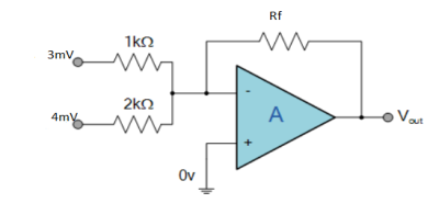
Solution :
We know,
Gain (Av) = =
= 
Hence,
Av1 = 
Av2 = 
Now, Output voltage Vo = Sum of the two amplified input signals
Vo = Av1 x V1 + Av2 x V2
Vo =(-5 x 3) + ( -2.5x 4) mV
Vo = -25mV
As the above output voltage is negative hence it is an inverting amplifier.
References:
1. Electronic Devices Circuit Theory - by Rober L. Boylestad 11th Edition, Pearson Publication, 2014
2. Microelectronic Circuits by A. S. Sedra and Kenneth C. Smith 7th Edition, Oxford University Press. 2017
3. Digital Design by M. Morris Mano, 5th Edition, Pearson Publication, 2016.