Module 4
Electrical Machines
I Ø transformers and electrostatics
Acc to input supply : I phase and  phase
phase
Acc to construction : core and shell type
Acc to 0/P : step up and step down
Construction of transformers (study only for MCQs)
Material used for core is (silicon steel) it is used for its (high permeability) and (low magnetic reluctance)  magnetic field produced is very strong
The core is formed of (stacks of laminated thin steel sheets) which are electrically isolated from each other. They are typically (0.35 to 0.5 mm thick)
We can used 2 ‘L’ shaped sheets or 2  shaped sheets for laminations
Construction and types
L.V. = low voltage H.V. = high voltage are mounted on same limb to minimum leakage .
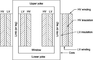
L.V. Winding placed inside and H.V. winding placed outside with (proper insulation between the winding as it is easy to insulated L.V. winding) than H.V. winding.
2. Sandwiched
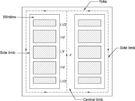
The H.V. and L.V. winding are divided into no. of small coils and there small windings are interleaved.
(the top and bottom winding are L.V. coils because they are close to core)
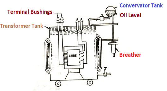
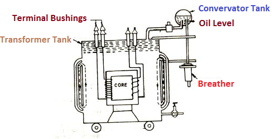
(To increase cooling surface are tubes or fins are provided)
However during contraction outside air can have moisture which will deteriorate the insulating properly of oil.
There is pipe connecting rain tank and conservator. On the pipe a protective device called Buccholz Relay is mounted.
When the Transformer is about to be faulty and draw range current the oil becomes very hot and decompose.
During this process different types of gases are liberated.(The Bucchoz Relay get operated by these gases) and gives an alarm to the operator. ɡȴ the fault continues to persist then there lay will trip off main circuit breaker to protect the Transformer.
An explosion Vent or relief value is the bent up pipe filled on the main tank.
(The explosion vent consist of aluminium of oil ) when the T/F becomes faulty the cooling oil get decomposed and various types of gases are liberated
(ɡȴ the gas pressure exodus certain level then the aluminium of oil (diagram) in explosion vent will burst) to release pressure. The will save main tank from getting damaged.
(Symbol and principal of operation)
It is a static device which can transfer electrical energy from one ac circuit to another ac circuit without change in frequency
It can increase or decrease the voltage but with corresponding decrease or increase in current
It works on Principle 
“Mutual Induction”
A major application of transformer is to increase voltage before transmitting electrical energy over a long distance through conductors and to again reduce voltage at place where it is to be used.
Symbol
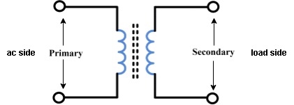
The winding which is connected to supply is called primary side
2. Secondary winding : (load side) for MCQs
The winding which is connected to load is called as secondary winding
It works on principle of mutual Induction ie “when 2 coil are inductively coupled and if current in one coil is changed uniformly then an emf get induced in another coil”


Core Diagram
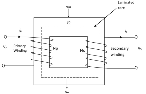
Shell Diagram:
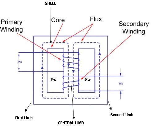
2 limbs
2. single magnetic circuit 2. Double magnetic ckt.
3. Winding encircles the core 3. Core encircles the winding
4. One window 4. Two window
5. Cylindrical type winding is used 5. Sandwich type is used
6. Easy to repair 6. Not easy repair
7. Preferred for Low voltage application 7. Preferred for high voltage application
8. Provides better cooling since winding 8. Does not provide effective cooling as
Are uniformly distributed on 2 limbs the winding are surrounding core.
4.1.1 Phasor diagram and performance testing
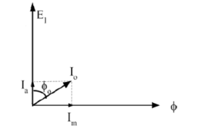
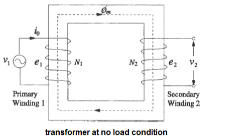
When the transformer is connected to the AC source, an electrical current pass in the primary winding and this current called No load current (Io).
This current causes a production of variable magnetic flux.
This magnetic flux cuts both the primary and the secondary winding and generates in each of them an opposite Electro Motive Force (E.M.F) proportional to the number of turns and the rate of change in the flux of time. And the No load current is divided into two compounds Ia, Im
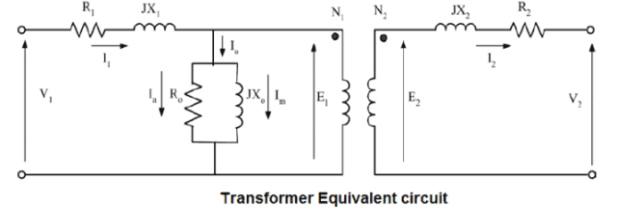
Ia: is the cause of iron loss
Im: is the cause of magnetizing circuit
Such that :
Ia = Io * cosφo
Im = Io * sinφo
Φo: the angle between current Io and voltage for primary side
Power of transformer at no load condition: Because the primary winding has physical resistance (R1) and inductive reactance (X1), the current of the load causes a voltage drop at the terminals of the primary winding shown in the following relationship
 =
=  +
+  *
* 
Z1 = [ R1 2 + X1 2] ½
At no load condition, the output power of transformer is equal to “Zero” and therefore the power withdrawn from the source (input power) is consumed in the loss of iron and copper So, we can neglect the losses of copper because of the small primary current and the absence of current in the secondary.
Po = V1 * Io * cosφo
This iron loss is consumed in the resistance of the magnetic circuit Ro and shown at the following relationship :
Ro = (V1/ Ia) = (V1/ Io * cosφo)
Also we can calculate reactance Xo from following relationship :
Xo = (V1/ Im) = (V1/ Io * sinφo)
So, We notice that the current (Io) is passed in the case of “on load ” or “without load” and also the iron loss is fixed as long as the transformer is connected to the rated operating voltage.
How to draw phasor diagram of transformer at no load condition:
If we assume that the voltage wave V1 is a sine wave, the current (Im) causing the magnetic flux is 90 degrees lagging and therefore the flux is also lagging at the same angle due to the flow of current in the inductive reactance
So,


 =
=  +
+  *
* 
Z1 = [ R1 2 + X1 2] ½
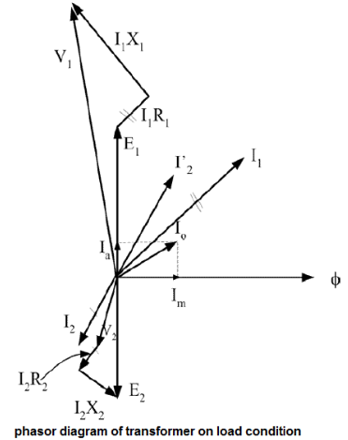
Phasor diagram of transformer on load condition:
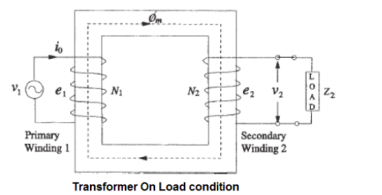
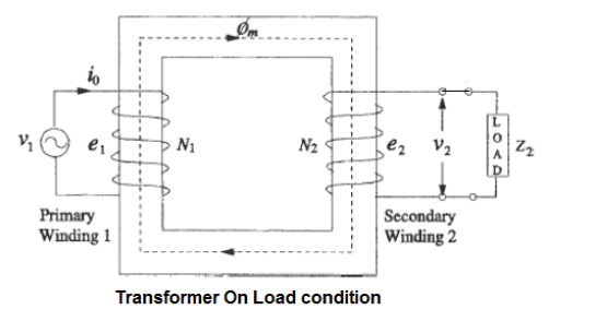
When a load is connected to the terminals of the secondary winding (Z2) , an electrical current passes in secondary side called the secondary winding current (I2) due to the impedance of the load. This current causes a magnetic flux in the iron core. this value of magnetic flux depends on the current of I2 So, This flux must be opposite by another counter flux in the primary winding.
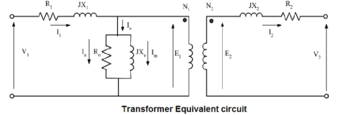
So, at loading condition the total current of the load (I2), I2 = (V2/Z2) is the total current which drawn by the load from the source so we can represent the phasor diagram of transformer as follows :
4.1.2 Induction Motors (Three Phase): Basic Principles
Consider- 3Ф slip ring I.M
Cut section diagram:-
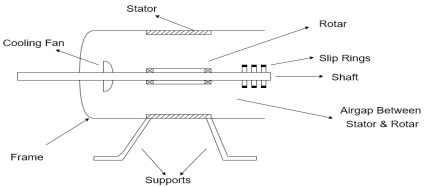
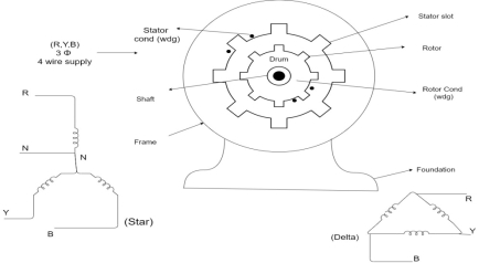
The induction motor has following important parts:-
Principle of operation of induction motor:

Types of induction motor:
Two main types depending upon the rotor
Induction motor are also available in 1Ф supply i.e.
1. Resistance split phase induction motor
2. Capacitor start induction motor
3. Capacitor start capacitor run induction motor
4. 1Ф induction motor i.e. A.C series motors
5. Shaded pole induction motor
Torque equation of induction motor:-
Torque produced in induction motor depends upon the following factors
1.The rotor power factors ( CosФ) under running condition
2.The rotor current under running condition
3. The part of RMF which induces EMF in rotor wdgi.e. flux (Ф)
We can mathematically say that,
 , As per DC (M) equation
But in case of induction motor
Suffix 1 -> used for stator/stator parts (qty)
Suffix 2-> used for rotor/rotor parts(qty)
Therefore,  ----(1)
 = flux that induces the EMF in rotor
 = rotor current under running condition
 = P.F of rotor
But, stator vtg
 also i.e
 ----(2)
Transformation ratio i.e. given by 
Therefore,
 and hence
 also
also
 at slip ’S’ is given by
And also  at slip ‘S’ is
  =S.
=S.
Hence  in equation can be replaced by
i.e.  U
U
 =
= ----(3)----(
 )
)
4 =
= ------(4)
Substract (3) and (4) into (1) equation we get,


 (N-m) , Torque equation of I.M.


At starting condition slip S=1
So, 
4.1.3 Rotating Magnetic Field
Rotating magnetic field is magnetic field which rotates in space about some point or axis. The North and South poles continuously rotates with a specific speed, called synchronous speed. All poly phase electrical machines are associated with rotating magnetic field in the air gap. Therefore, an understanding of rotating magnetic field produced by poly phase winding is very important to analyze and understand the principle and operation of electrical machine viz. Synchronous Machine and Induction Machine.
Condition for Generation of Rotating Magnetic Field
When a balanced poly phase current flows in the balanced poly phase winding, a rotating magnetic field is produced. The necessary condition for generation of rotating magnetic field is that “the time angle displacement between the currents and space angle displacement between the winding axes must be equal.”
Let us consider an example for better understanding of the above mentioned condition. In the figure below, three coils a, b and c with their magnetic axis coincident are excited by three phase balanced current Imsinωt, Imsin(ωt-120°) and Imsin(ωt+120°).
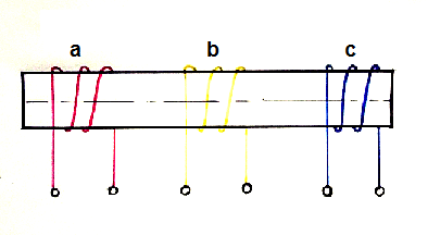
In this case, the time angle displacement between the currents is 120 degree but the space angle displacement between the winding axes zero. Therefore, rotating magnetic field will not be produced.
4.1.4 Equivalent circuit
The equivalent circuit of any machine shows the various parameter of the machine such as its Ohmic losses and also other losses.
The losses are modelled just by inductor and resistor . The copper losses are occurred in the windings so the winding resistance is taken into account. Also, the winding has inductance for which there is a voltage drop due to inductive reactance and also a term called power factor comes into the picture.
Here, R1 is the winding resistance of the stator.
X1 is the inductance of the stator winding.
Rc is the core loss component.
XM is the magnetizing reactance of the winding.
R2/s is the power of the rotor, which includes output mechanical power and copper loss of rotor.
If we draw the circuit with referred to the stator then the circuit will look like-

Here all the other parameters are same except-
R2’ is the rotor winding resistance with referred to stator winding.
X2’ is the rotor winding inductance with referred to stator winding.
R2(1 – s) / s is the resistance which shows the power which is converted to mechanical power output or useful power. The power dissipated in that resistor is the useful power output or shaft power.
4.1.5 Phasor diagram
Two Conditions for production of Rotating Magnetic field :

The three phase currents flow simultaneously through the windings and are displaced from each other by 120 degree electrical. Each alternating phase current produces its own flux which is sinusoidal. So all three fluxes are sinusoidal and are separated from each other by 120 degree. If the phase sequence of the windings is R-Y-B, then mathematical equations for the instantaneous values of the three fluxes ΦR, ΦB, ΦY can be written as, (The flux ΦR is taken as reference phasor) :
ΦR = Φm sin (ωt) = Φm sin θ
ΦY = Φm sin (ωt – 120∘) = Φm sin( θ – 120∘)
ΦB = Φm sin (ωt – 240∘) = Φm sin( θ – 240∘)
As windings are identical and supply is balanced, the magnitude of each flux is . Due to phase sequence R-Y-B, flux ΦY lags behind ΦR by 120 degree and ΦB lags ΦY by 120 degree. So ΦB ultimately lags ΦR by 240 degree.
ΦR = Φm sin(0∘) = 0
ΦY = Φm sin(-120∘) = – 0.866 Φm
ΦB = Φm sin(-240∘) = + 0.866 Φm
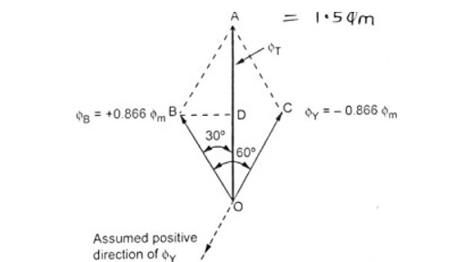
The phasor addition is shown in the figure. BD is drawn perpendicular from B on ΦT. It bisects ΦT.
OD = DA = ΦT / 2
In triangle OBD, angle BOD = 30∘
cos(30∘) = OD / OB = (ΦT / 2) / 0.866Φm
⇒ ΦT = 2 × 0.866 Φm × cos(30∘) = 1.5 Φm
So magnitude of ΦT is 1.5 Φm and its position is vertically upwards at θ = 0∘.
ΦR = Φm sin(60∘) = + 0.866 Φm
ΦY = Φm sin(-60∘) = – 0.866 Φm
ΦB = Φm sin(-180∘) = 0

So ΦR is positive and ΦY is negative and hence drawing in appropriate directions we phasor diagram as shown in figure.
Doing the same construction, drawing perpendicular from B on ΦT at D we get the same results.
ΦT = 1.5 Φm
REPORT THIS AD
REPORT THIS AD
But it can be seen that though its magnitude is 1.5 Φm it has rotated through 60∘ in space, in clockwise direction, from its previous position.
ΦR = Φm sin(120∘) = + 0.866 Φm
ΦY = Φm sin(0∘) = 0
ΦB = Φm sin(-120∘) = – 0.866 Φm

After doing the same construction as before it can be proved again that,
ΦT = 1.5 Φm
But it can be seen that though its magnitude is 1.5 Φm it has rotated through 120∘ in space, in clockwise direction, from its 1st position θ = 0∘.
ΦR = Φm sin(180∘) = 0
ΦY = Φm sin(60∘) = + 0.866 Φm
ΦB = Φm sin(-160∘) = – 0.866 Φm
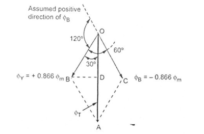
Magnitude of net flux remains same, if further rotated through 60∘ from its previous position in clockwise direction.
4.1.6 Torque-Speed Characteristics Basics of DC machines
Torque equation of a D.C. motor
The turning all twisting force about an exists is called torque.
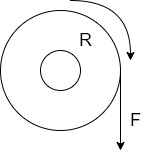
Consider A wheel of radius R meters coated upon circumferential force F Newton as shown in figure (a)
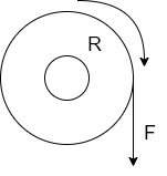
The wheel is rotating at a speed of N r.p.m. then its angular speed is
W =  rad/sec
So work done in one revolution is
W=F×distance travelled in one revolution
= F×  Joules
P=power developed=
= (F×R) ×
P= T×W watts
Where T=torque in Nm and w = angular speed in rad/sec
Let  the gross torque developed by the armature of the motor. It is also called armature torque.
The gross mechanical power developed in the armature is  as seen from the power equation.
So if speed of the motor is N r.p.m then
Power in armature=armature torque×w i.e.  .
.
But  in a motor is given by


This is the torque equation of D.C. motor
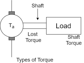
Types of torque in the motor

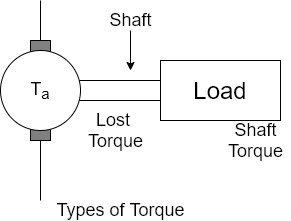
the torque which is available at the shaft for doing the useful work is known as Load torque or shaft torque denoted as

The shaft torque magnitude is always less than the armature torque (
The speed of the motor remains same all along the shaft say N r.p.m. Then the product of shaft torque  and the angular speed w rad/sec is called power available at the shaft i.e. net output of the motor. The maximum power a motor can deliver to the load safety is called output rating of a motor. Generally it is expressed in H.P. it is called H.P rotating of a motor.
Net o/p of motor=Pout= w
w
No load condition of the motor
On no load the load requirement is absent  =0
=0
This does not mean that motor is at half. The motor can rotate at No r.p.m on no load.
The motor draws on armature current of 

Where  is back e.m.f on no load proportional to speed
Now armature torque  for a motor is

As flux is present and armature current is is present, Hence  i.e. armature torque exist on no load.
 but on no load,
 =0
=0

So on no load motor produces a torque  which satisfies the friction, windage and iron losses of the motor.
Power developed ( =friction, windage and iron losses
Where  =back emf on no load
And  =armature current drawn on no load
This component of stray losses i.e.  practically assumed to be constant though the load on the motor is changed from 0 to the fall capacity of the motor.
1) A 4 pole D.C. motor takes a 50A armature current. The armature has lab connected 480 conductors. The flux per Pole is 20 mWb . Calculate the gross torque developed by the armature of the motor.
 =20mWb=


 Nm
Nm
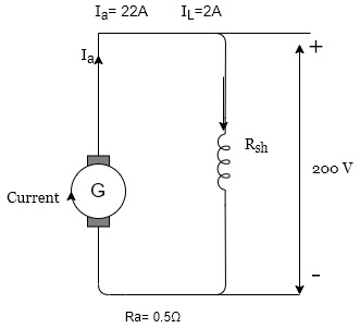
The field current in a D.C. shunt machine is 2A and the line current is 20A at 200V. Calculate the
As a Generator

And line current=20A
These characteristics can be derived from above two characteristics
Motor characteristics
This graph is similar to speed armature current characteristics as torque is proportional to the armature current this curve shows that the speed almost remains constant torque changes from no load to full load conditions.

Characteristics of DC series motor
For the series motor the series field winding is carrying the entire armature current hence,

The torque in case of series motor is proportional to the square of the armature current this relation is parabolic in nature as shown in the figure
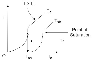
As load increases armature current increases and torque produced increases proportional to the square of the armature current upto a certain limit.
As the entire current passes through the series field there is a property of an electromagnet called saturation may occur.
Saturation means though the current through the winding increases the flux produced remains constant hands after saturation the characteristics take the shape of straight line is flux becomes constant as shown.
The difference between  is loss torque .
 shown in figure
Speed armature current characteristics
From the speed equation we get

As  in case of series motor
The values of  are so small that the effect of change in
  on the speed overrides effect of change in
  on the speed . Hence in the speed equation
  and can be assumed constant
So speed equation reduces to

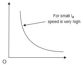
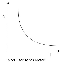
Speed armature current characteristics is rectangular hyperbola type as shown in figure
Speed torque characteristics
In case of series motors

Hence we can write 
Thus as torque increases when load increases the speed decreases.
On no load torque is very less and hence speed increases to dangerously high value.
Thus the nature of the speed torque characteristics is similar to the nature of the speed armature current characteristics.
Speed control of DC shunt motor
The set of for speed control of DC shunt motor using the flux control technique is shown in figure.
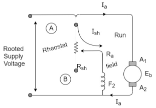
In order to change speed we have to change flux this can be achieved by changing the field current the field current can be changed by changing the value of rheostat R, connected in series with the field winding as shown in figure
See at the time of starting we need to run the motor slowly that means the clock should be maximum because

To obtain maximum Flux the field current should be maximum for this the value of rheostat(R) should be maximum.
Hence at the time of starting the variable point at rheostat is kept at point A and figure (a)
A rated constant supply voltage is applied to the set up so aerated field current will flow.
Hence a rated flux is produced which ultimately result in a rated speed of the motor.
How to very speed?
This speed can be varied by varying the field current as we increase the resistance R of the rheostat by sliding the movable contact from point A to b in figure be the field current decrease.
So the flux decreases this results increasing the motor speed
The variation in speed is shown graphically in figure
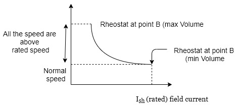
When the rheostat is at point A. The rated field current is supplied and motor rotates at its rated speed.
As R is increased the speed increases.
Note that we use this technique to control the motor speed above its rated value as shown in figure 2
Merits of the flux control methods


Demerits of flux control method
Rheostatic control or armature voltage control technique
The setup for the armature voltage control technique of speed control for DC shunt motor is shown in figure below
A rheostat R is connected in series with armature winding by varying the value of R we can vary the voltage that appears across the armature.
Since the speed N is directly proportional to armature voltage, it is possible to change the speed by changing the value of rheostat R.
The field winding is connected across the normal voltage v and the field current remains constant hence flux is constant and equal to its rated value.
Initially the sliding contact of the Rheostat is adjusted to be at point A. i.e. minimum value of R. The equivalent circuit for this situation is shown figure a
4.1.7 EMF Equation
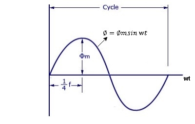
As primary winding excited by the a sinusoidal alternating voltage an alternating current flows in the winding producing an alternating varying flux Ø
Ø = Øm sin wt
As per Faradays Law of Electromagnetic Induction emf E1 is induced
E1 = N1 
E1 = N1  (Ø Sin wt)
= - N1 Øm w Cos wt
Sin (90-wt)
= - Sin (wt-90)
 E1 = N1 Øm w Sin (wt-90)
 w =
w = 
 E1 =
E1 =  N1 Ø m Sin (wt-90)
Max value of E1 = E max
Is when Sin (wt-90) =  1
1
E1 max =  N1 Ø m
Hence rms value of induced EMF in primary winding
E1 rms =  =
= 
 E1 = 4.44 F Ø m N1
 Similarly RMS value of induced EMF in secondary wdg Is
E2 = 4.44 F Ø m N2
4.1.8 Torque Equation
When armature conductors of a DC motor carry current in the presence of stator field flux, a mechanical torque is developed between the armature and the stator. Torque is given by the product of the force and the radius at which this force acts.
= (force × circumference × no. of revolutions) / time
= (F × 2πr × N) / 60 (Joules per second) .... eq. 2.1
But, F × r = T and 2πN/60 = angular velocity ω in radians per second. Putting these in the above equation 2.1
Net power developed in the armature = P = T × ω (Joules per second)
Armature torque (Ta)
Therefore, mechanical power = electrical power
That means, Ta × 2πN/60 = Eb.Ia
Ta = (PZ / 2πA) × Φ.Ia(N-m)
The term (PZ / 2πA) is practically constant for a DC machine. Thus, armature torque is directly proportional to the product of the flux and the armature current i.e. Ta ∝ Φ.Ia
Shaft Torque (Tsh)
Due to iron and friction losses in dc machine , the total developed armature torque is not available at the shaft of the machine. Some torque is lost, and therefore, shaft torque is always less than the armature torque.
Shaft torque of a DC motor is given as,
Tsh = output in watts / (2πN/60) ....(where, N is speed in RPM)
4.1.9 Methods of Excitation
There are three methods of excitation, and thus three main types of DC generators:
Permanent Magnet DC Generators – Field coils excited by permanent magnets
Separately Excited DC Generators – Field coils excited by some external source
Self -Excited DC generator – Field coils excited by the generator itself
Separately Excited DC Generator
These are the generators whose field magnets are energized by some external DC source, such as a battery.
A circuit diagram of separately excited DC generator is shown in the figure below. The symbols below are:
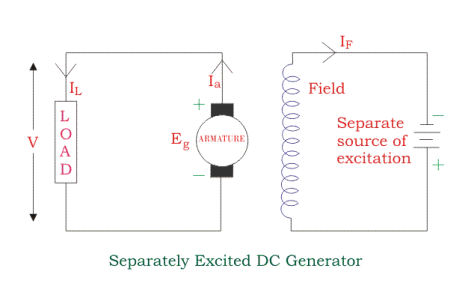
Voltage drop in the armature = Ia × Ra (R/sub>a is the armature resistance)
Let,
Ia = IL = I
Then,
Voltage across the load V = I Ra
Power generated is equal to
Pg = Eg X I
And power delivered to the external load is equal to
PL = V x I
Self Excited DC Generators
Self-excited DC generators are generators whose field magnets are energized by the current supplied by themselves. In these type of machines, field coils are internally connected with the armature.
Due to residual magnetism, some flux is always present in the poles. When the armature is rotated, some EMF is induced. Hence some induced current is produced. This small current flows through the field coil as well as the load and thereby strengthening the pole flux.
As the pole flux strengthened, it will produce more armature EMF, which cause the further increase of current through the field. This increased field current further raises armature EMF, and this cumulative phenomenon continues until the excitation reaches the rated value.
According to the position of the field coils,self excited DC generator may be classified as:
Series Wound Generator
In these type of generators, the field windings are connected in series with armature conductors, as shown in the figure below.
Whole current flows through the field coils as well as the load. As series field winding carries full load current it is designed with relatively few turns of thick wire. The electrical resistance of series field winding is therefore very low (nearly 0.5Ω ).
Here:
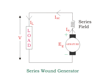
Then,
Ia = Isc = IL = I
Voltage across the load is equal to,
V = Eg – I (Ia x Ra)
Power generated is equal to,
Pg = Eg x I
Power delivered to the load is equal to,
PL = V x I
Shunt Wound DC Generators
In these type of DC generators, the field windings are connected in parallel with armature conductors, as shown in the figure below. In shunt wound generators the voltage in the field winding is same as the voltage across the terminal.
Here:
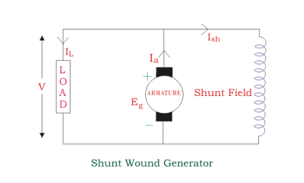
Here armature current Ia is dividing in two parts – one is shunt field current Ish, and another is load current IL.
So,
Ia = Ish + IL
The effective power across the load will be maximum when IL will be maximum. So, it is required to keep shunt field current as small as possible. For this purpose the resistance of the shunt field winding generally kept high (100 Ω) and large no of turns are used for the desired EMF.
Shunt field current is equal to,
Ish = V/ Rsh
Voltage across the load is equal to,
V = Eg – Ia Ra
Power generated is equal to,
Pg = Eg x Ia
Power delivered to the load is equal to,
PL = V x IL
References: