Unit 4
Mechanical Measurements
Concept of measurement:
Measurement, the process of associating numbers with physical quantities and phenomena. Measurement is fundamental to the sciences; to engineering, construction, and other technical fields; and to almost all everyday activities. For that reason the elements, conditions, limitations, and theoretical foundations of measurement have been much studied. See also measurement system for a comparison of different systems and the history of their development.
Measurements may be made by unaided human senses, in which case they are often called estimates, or, more commonly, by the use of instruments, which may range in complexity from simple rules for measuring lengths to highly sophisticated systems designed to detect and measure quantities entirely beyond the capabilities of the senses, such as radio waves from a distant star or the magnetic moment of a subatomic particle. (See instrumentation.)
Measurement begins with a definition of the quantity that is to be measured, and it always involves a comparison with some known quantity of the same kind. If the object or quantity to be measured is not accessible for direct comparison, it is converted or “transduced” into an analogous measurement signal. Since measurement always involves some interaction between the object and the observer or observing instrument, there is always an exchange of energy, which, although in everyday applications is negligible, can become considerable in some types of measurement and thereby limit accuracy.
According to the National Council of Teachers of Mathematics (2000), "Measurement is the assignment of a numerical value to an attribute of an object, such as the length of a pencil. At more-sophisticated levels, measurement involves assigning a number to a characteristic of a situation, as is done by the consumer price index." An early understanding of measurement begins when children simply compare one object to another. Which object is longer? Which one is shorter? At the other extreme, researchers struggle to find ways to quantify their most elusive variables. The example of the consumer price index illustrates that abstract variables are, in fact, human constructions. A major part of scientific and social progress is the invention of new tools to measure newly constructed variables.
To be able to assign a numerical value to an attribute of an object, we must first be able to identify the attribute, and then we must have some kind of unit against which to compare that attribute. Most often we need a measurement tool that supplies us with our units. If our units are smaller than the attribute in question, then our measurement is in terms of numbers (quantities) of those units. On the other hand, if our units are larger than the attribute in question, then our measurement is in terms of parts (partitions) of the unit. Most often measurement includes a quantity of whole units along with a part of a unit. The fractional part of a unit determines the precision with which we measure. Greater precision results from smaller partitions.
The units that we use to measure are most often standard units, which means that they are universally available and are the same size for all who use them. Sometimes we measure using nonstandard units, which means that we are using units that we have invented and that are unknown outside our local context. Either standard or nonstandard units may be used in the classroom, depending on the teachers' immediate objectives.
Types of Measurement:
Generally, there are three types of measurement:
(i) Direct; (ii) Indirect; and Relative.
Direct; to find the length and breadth of a table involves direct measurement and this is always accurate if the tool is valid.
Indirect; to know the quantity of heat contained by a substance involves indirect measurement for we have to first find out the temperature of the substance with the help of a thermometer and then we can calculate the heat contained by the substance.
Relative: To measure the intelligence of a boy involves relative measurement, for the score obtained by the boy in an intelligence test is compared with norms. It is obvious that psychological and educational measurements are relative.
Errors in measurements:
The measurement error is defined as the difference between the true or actual value and the measured value. The true value is the average of the infinite number of measurements, and the measured value is the precise value.
Types of Errors in Measurement
The error may arise from the different source and are usually classified into the following types. These types are
Gross Errors
Systematic Errors
Random Errors
1. Gross Errors
The gross error occurs because of the human mistakes. For examples consider the person using the instruments takes the wrong reading, or they can record the incorrect data. Such type of error comes under the gross error. The gross error can only be avoided by taking the reading carefully.
For example – The experimenter reads the 31.5ºC reading while the actual reading is 21.5Cº. This happens because of the oversights. The experimenter takes the wrong reading and because of which the error occurs in the measurement.
Such type of error is very common in the measurement. The complete elimination of such type of error is not possible. Some of the gross errors easily detected by the experimenter but some of them are difficult to find. Two methods can remove the gross error.
Two methods can remove the gross error. These methods are
2. Systematic Errors
The systematic errors are mainly classified into three categories.
(i) Instrumental Errors
These errors mainly arise due to the three main reasons.
(a) Inherent Shortcomings of Instruments – Such types of errors are inbuilt in instruments because of their mechanical structure. They may be due to manufacturing, calibration or operation of the device. These errors may cause the error to read too low or too high.
For example – If the instrument uses the weak spring then it gives the high value of measuring quantity. The error occurs in the instrument because of the friction or hysteresis loss.
(b) Misuse of Instrument – The error occurs in the instrument because of the fault of the operator. A good instrument used in an unintelligent way may give an enormous result.
For example – the misuse of the instrument may cause the failure to adjust the zero of instruments, poor initial adjustment, using lead to too high resistance. These improper practices may not cause permanent damage to the instrument, but all the same, they cause errors.
(c) Loading Effect – It is the most common type of error which is caused by the instrument in measurement work. For example, when the voltmeter is connected to the high resistance circuit it gives a misleading reading, and when it is connected to the low resistance circuit, it gives the dependable reading. This means the voltmeter has a loading effect on the circuit.
The error caused by the loading effect can be overcome by using the meters intelligently. For example, when measuring a low resistance by the ammeter-voltmeter method, a voltmeter having a very high value of resistance should be used.
(ii) Environmental Errors
These errors are due to the external condition of the measuring devices. Such types of errors mainly occur due to the effect of temperature, pressure, humidity, dust, vibration or because of the magnetic or electrostatic field. The corrective measures employed to eliminate or to reduce these undesirable effects are
(iii) Observational Errors
Such types of errors are due to the wrong observation of the reading. There are many sources of observational error. For example, the pointer of a voltmeter resets slightly above the surface of the scale. Thus an error occurs (because of parallax) unless the line of vision of the observer is exactly above the pointer. To minimise the parallax error highly accurate meters are provided with mirrored scales.
3. Random Errors
The error which is caused by the sudden change in the atmospheric condition, such type of error is called random error. These types of error remain even after the removal of the systematic error. Hence such type of error is also called residual error.
Different Measures of Error

TEMPERATURE MEASUREMENT:
Temperature is the measurement of heat (thermal energy) associated with the movement (kinetic energy) of the molecules of a substance. Thermal energy always flows from a warmer body to a cooler body. In this case, temperature is defined as an intrinsic property of matter that quantifies the ability of one body to transfer thermal energy to another body.
Temperature Scales
Several temperature scales have been developed to provide a standard for indicating the temperatures of substances. The most commonly used scales include the Fahrenheit, Celsius, Kelvin, and Rankine temperature scales. The Fahrenheit (·F) and Celsius (·C) scales are based on the freezing point and boiling point of water. The freezing point of a substance is the temperature at which it changes its physical state from a liquid to a solid. The boiling point is the temperature at which a substance changes from a liquid state to a gaseous state. To convert a Fahrenheit reading to its equivalent Celsius reading, the following equation is used.
·C = 5/9 (·F - 32)
In order to convert from Celsius to Fahrenheit, the following equation is used.
·F = 9/5 (·C) + 32
The Kelvin (K) and Rankine (·R) scales are typically used in engineering calculations and scientific research. They are based on a temperature called absolute zero. Absolute zero is a theoretical temperature where there is no thermal energy or molecular activity. Using absolute zero as a reference point, temperature values are assigned to the points at which various physical phenomena occur, such as the freezing and boiling points of water.
International Practical Temperature Scale
For ensuring an accurate and reproducible temperature measurement standard, the International Practical Temperature Scale (IPTS) was developed and adopted by the international standards community. The IPTS assigns the temperature numbers associated with certain reproducible conditions, or fixed points, for a variety of substances. These fixed points are used for calibrating temperature measuring instruments. They include the boiling point, freezing point, and triple point.
Temperature Measuring Devices
Temperature measuring devices are classified into two major groups, temperature sensors and absolute thermometers.
Sensors are classified according to their construction. Three of the most common types of temperature sensors are thermocouples, resistance temperature devices (RTDs), and filled systems. Typically, temperature indications are based on material properties such as the coefficient of expansion, temperature dependence of electrical resistance, thermoelectric power, and velocity of sound.
Calibrations for temperature sensors are specific to their material of construction. Temperature sensors that rely on material properties never have a linear relationship between the measurable property and temperature. The accuracy of absolute thermometers does not depend on the properties of the materials used in their construction.
The temperature of an object or substance can be calculated directly from measurements taken with an absolute thermometer. Types of absolute thermometers include the gas bulb thermometer, radiation pyrometer, noise thermometer, and acoustic interferometer. The gas bulb thermometer is the most commonly used. Temperature measuring devices can also be categorized according to the manner in which they respond to produce a temperature measurement. In general, the response will be either mechanical or electrical. Mechanical temperature devices respond to temperature by producing mechanical action or movement. Electrical temperature devices respond to temperature by producing or changing an electrical signal.
Temperature is defined as the energy level of matter which can be evidenced by some change in that matter. Temperature measuring sensors come in a wide variety and have one thing in common: they all measure temperature by sensing some change in a physical characteristic.
The seven basic types of temperature measurement sensors discussed here are thermocouples, resistive temperature devices (RTDs, thermistors), infrared radiators, bimetallic devices, liquid expansion devices, molecular change-of-state and silicon diodes.
1. Thermocouples
Thermocouples are voltage devices that indicate temperature measurement with a change in voltage. As temperature goes up, the output voltage of the thermocouple rises - not necessarily linearly.
Often the thermocouple is located inside a metal or ceramic shield that protects it from exposure to a variety of environments. Metal-sheathed thermocouples also are available with many types of outer coatings, such as Teflon, for trouble-free use in acids and strong caustic solutions.
2. Resistive Temperature Measuring Devices
Resistive temperature measuring devices also are electrical. Rather than using a voltage as the thermocouple does, they take advantage of another characteristic of matter which changes with temperature - its resistance. The two types of resistive devices we deal with at OMEGA Engineering, Inc., in Stamford, Conn., are metallic, resistive temperature devices (RTDs) and thermistors. In general, RTDs are more linear than are thermocouples. They increase in a positive direction, with resistance going up as temperature rises. On the other hand, the thermistor has an entirely different type of construction. It is an extremely nonlinear semi conductive device that will decrease in resistance as temperature rises.
3. Infrared Sensors
Infrared sensors are non-contacting sensors. As an example, if you hold up a typical infrared sensor to the front of your desk without contact, the sensor will tell you the temperature of the desk by virtue of its radiation–probably 68°F at normal room temperature.
In a non-contacting measurement of ice water, it will measure slightly under 0°C because of evaporation, which slightly lowers the expected temperature reading.
4. Bimetallic Devices
Bimetallic devices take advantage of the expansion of metals when they are heated. In these devices, two metals are bonded together and mechanically linked to a pointer. When heated, one side of the bimetallic strip will expand more than the other. And when geared properly to a pointer, the temperature measurement is indicated.
Advantages of bimetallic devices are portability and independence from a power supply. However, they are not usually quite as accurate as are electrical devices, and you cannot easily record the temperature value as with electrical devices like thermocouples or RTDs; but portability is a definite advantage for the right application.
5. Thermometers
Thermometers are well-known liquid expansion devices also used for temperature measurement. Generally speaking, they come in two main classifications: the mercury type and the organic, usually red, liquid type. The distinction between the two is notable, because mercury devices have certain limitations when it comes to how they can be safely transported or shipped.
For example, mercury is considered an environmental contaminant, so breakage can be hazardous. Be sure to check the current restrictions for air transportation of mercury products before shipping.
6. Change-of-state Sensors
Change-of-state temperature sensors measure just that– a change in the state of a material brought about by a change in temperature, as in a change from ice to water and then to steam. Commercially available devices of this type are in the form of labels, pellets, crayons, or lacquers.
For example, labels may be used on steam traps. When the trap needs adjustment, it becomes hot; then, the white dot on the label will indicate the temperature rise by turning black. The dot remains black, even if the temperature returns to normal.
7. Silicon Diode
The silicon diode sensor is a device that has been developed specifically for the cryogenic temperature range. Essentially, they are linear devices where the conductivity of the diode increases linearly in the low cryogenic regions.
Whatever sensor you select, it will not likely be operating by itself. Since most sensor choices overlap in temperature range and accuracy, selection of the sensor will depend on how it will be integrated into a system.
8. Radiation Pyrometers.
No contacting temperature measurement can be achieved through the use of radiation, or optical, pyrometers. The high temperature limits of radiation pyrometers exceed the limits of most other temperature sensors. Radiation pyrometers are capable of measuring temperatures to approximately 4000·C without touching the object being measured.
Factors Affecting Accuracy
There are several factors, of effects, that can cause steady state measurement errors. These effects include:
Pressure measurement:
Pressure is defined as force per unit area that a fluid exerts on its surroundings. Pressure, P, is a function of force, F, and area, A:
P = F/A
The SI unit for pressure is the Pascal (N/m2), but other common units of pressure include pounds per square inch (psi), atmospheres (atm), bars, and inches of mercury (in. Hg), millimeters of mercury (mm Hg), and torr.
A pressure measurement can be described as either static or dynamic. The pressure in cases with no motion is static pressure. Examples of static pressure include the pressure of the air inside a balloon or water inside a basin. Often, the motion of a fluid changes the force applied to its surroundings. For example, say the pressure of water in a hose with the nozzle closed is 40 pounds per square inch (force per unit area). If you open the nozzle, the pressure drops to a lower value as you pour out water. A thorough pressure measurement must note the circumstances under which it is made. Many factors including flow, compressibility of the fluid, and external forces can affect pressure.
Pressure measurement methods
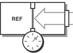
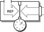
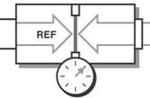
A pressure measurement can further be described by the type of measurement being performed. The three methods for measuring pressure are absolute, gauge, and differential. Absolute pressure is referenced to the pressure in a vacuum, whereas gauge and differential pressures are referenced to another pressure such as the ambient atmospheric pressure or pressure in an adjacent vessel.
Absolute Pressure | Gauge Pressure | Differential Pressure |
|
|
|
Figure. Pressure Sensor Diagrams for Different Measurement Methods
Absolute Pressure
The absolute measurement method is relative to 0 Pa, the static pressure in a vacuum. The pressure being measured is acted upon by atmospheric pressure in addition to the pressure of interest. Therefore, absolute pressure measurement includes the effects of atmospheric pressure. This type of measurement is well-suited for atmospheric pressures such as those used in altimeters or vacuum pressures. Often, the abbreviations Paa (Pascal’s absolute) or psia (pounds per square inch absolute) are used to describe absolute pressure.
Gauge Pressure
Gauge pressure is measured relative to ambient atmospheric pressure. This means that both the reference and the pressure of interest are acted upon by atmospheric pressures. Therefore, gauge pressure measurement excludes the effects of atmospheric pressure. These types of measurements include tire pressure and blood pressure measurements. Similar to absolute pressure, the abbreviations Pag (Pascal’s gauge) or psig (pounds per square inch gauge) are used to describe gauge pressure.
Differential Pressure
Differential pressure is similar to gauge pressure; however, the reference is another pressure point in the system rather than the ambient atmospheric pressure. You can use this method to maintain relative pressure between two vessels such as a compressor tank and an associated feed line. Also, the abbreviations Pad (Pascal’s differential) or PSID (pounds per square inch differential) are used to describe differential pressure.
How do pressure sensors work?
Different measurement conditions, ranges, and materials used in the construction of a sensor lead to a variety of pressure sensor designs. Often you can convert pressure to some intermediate form, such as displacement, by detecting the amount of deflection on a diaphragm positioned in line with the fluid. The sensor then converts this displacement into an electrical output such as voltage or current. Given the known area of the diaphragm, you can then calculate pressure. Pressure sensors are packaged with a scale that provides a method to convert to engineering units.
The three most universal types of pressure transducers are the bridge (strain gage based), variable capacitance, and piezoelectric.
1) Bridge-Based
All the pressure sensors, Wheatstone bridge (strain based) sensors are the most common because they offer solutions that meet varying accuracy, size, ruggedness, and cost constraints. Bridge-based sensors can measure absolute, gauge, or differential pressure in both high- and low-pressure applications. They use a strain gage to detect the deformity of a diaphragm subjected to the applied pressure.
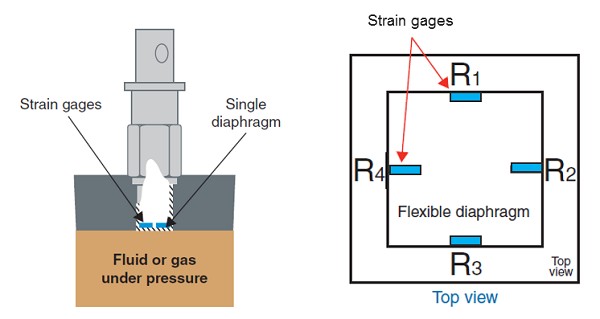
Figure Cross Section of a Typical Bridge-Based Pressure Sensor
When a change in pressure causes the diaphragm to deflect, a corresponding change in resistance is induced on the strain gage, which you can measure with a conditioned DAQ system. You can bond foil strain gages directly to a diaphragm or to an element that is connected mechanically to the diaphragm. Silicon strain gages are sometimes used as well. For this method, you etch resistors on a silicon-based substrate and use transmission fluid to transmit the pressure from the diaphragm to the substrate.
2) Capacitive Pressure Sensors
A variable capacitance pressure transducer measures the change in capacitance between a metal diaphragm and a fixed metal plate. The capacitance between two metal plates changes if the distance between these two plates changes due to applied pressure.
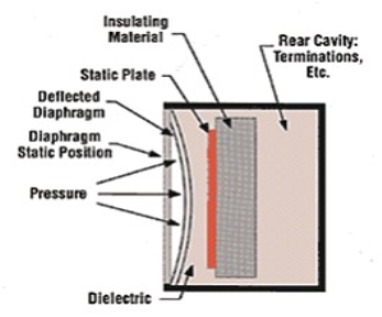
Figure Capacitance Pressure Transducer
3) Piezoelectric Pressure Sensors
Piezoelectric sensors rely on the electrical properties of quartz crystals rather than a resistive bridge transducer. These crystals generate an electrical charge when they are strained. Electrodes transfer the charge from the crystals to an amplifier built into the sensor. These sensors do not require an external excitation source, but they are susceptible to shock and vibration.
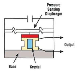
4) Conditioned Pressure Sensors
Sensors that include integrated circuitry, such as amplifiers, are referred to as amplified sensors. These types of sensors may be constructed using bridge-based, capacitive, or piezoelectric transducers. In the case of a bridge-based amplified sensor, the unit itself provides completion resistors and the amplification necessary to measure the pressure directly with a DAQ device. Though excitation must still be provided, the accuracy of the excitation is less important.
5) Optical Pressure Sensors
Pressure measurement using optical sensing has many benefits including noise immunity and isolation. Read Fundamentals of FBG Optical Sensing for more information about this method of measurement.
Velocity measurement:
The velocity of an object is the rate of change of its position with respect to a frame of reference, and is a function of time. Velocity is equivalent to a specification of an object's speed and direction of motion (e.g. 60 km/h to the north). Velocity is a fundamental concept in kinematics, the branch of classical mechanics that describes the motion of bodies.
The methods of measuring the velocity of liquids or gases can be classified into three main groups: kinematic, dynamic and physical.
In kinematic measurements, a specific volume, usually very small, is somehow marked in the fluid stream and the motion of this volume (mark) is registered by appropriate instruments. Dynamic methods make use of the interaction between the flow and a measuring probe or between the flow and electric or magnetic fields. The interaction can be hydrodynamic, thermodynamic or magneto hydrodynamic.
For physical measurements, various natural or artificially organized physical processes in the flow area under study, whose characteristics depend on velocity, are monitored.
The main advantage of kinematic methods of velocity measurements is their perfect character, and also their high space resolution. By these methods, we can find either the time the marked volume covers a given path, or the path length covered by it over a given time interval. The mark can differ from the surrounding fluid flow in temperature, density, charge, degree of ionization, luminous emittance, index of refraction, radioactivity, etc.
The marks can be created by impurities introduced into the fluid flow in small portions at regular intervals. The mark must follow the motion of the surrounding medium accurately. The motion of marks is distinguished by the method of their registration, into non-optical and optical kinematic methods. In the probe non-optical method which traces thermal no uniformities, a probe consisting of three filaments located in parallel plates used. The thermal trace is registered by two receiving wires located a distance 1 from the central wire. By registering the time Δt between the pulse heat emitted from the central wire and the thermal response of the receiving wire, we can determine the velocity u = l/Δt. Depending on which receiving wire receives a thermal pulse, we can define the direction of flow.
Marks consisting of regions of increased ion content are also widely used. To create ion marks, a spark or a corona discharge or an optical breakdown under the action of high-pulse laser radiation is used. In tracing by radioactive isotopes, the marks are created by injecting radioactive substances into the fluid flow; the times of passing selected locations by the marks are registered with the help of ionizing-radiation detectors.
Optical kinematic methods use cine and still photography to follow the motion of marks. Three main types of photography are used: cine photography, still photography with stroboscopic lighting and photo tracing. In cine photography, to determine the velocity, successive frames are aligned and the distance between the corresponding positions of the mark is measured. In the stroboscopic visualization method, several positions of the mark are registered on a single frame (a discontinuous track), which correspond to its motion between successive light pulses. Two components of the instantaneous velocity vector are determined by the distance between the particle positions. Typical of the marks used are 3-5 mm aluminum powder particles or small bubbles of gas generated electrolytic ally in the circuit of the experimental plant. Of vital importance in this method is the accuracy of measurement of the time intervals between the flashes.
In the photo tracing method, the motion of the mark is recorded by projecting the image of the mark through a diaphragm (in the form of a thin slit oriented along the fluid flow) onto a film located on a drum rotating at a certain speed. The mark image leaves a trace on the film whose trajectory is determined by adding the two vectors: the vector of mark motion and the vector of film motion. The slope angle of a tangent to this trajectory is proportional to the velocity of mark motion. Further information on the photographic technique is given in the article on Tracer Methods.
Laser Doppler anemometers can also be classified as kinematic techniques (see Anemometers, Laser Doppler).
Among the dynamic methods the most generally employed are, because of the simplicity of the corresponding instruments, the methods based on hydrodynamic interaction between the primary converter and the fluid flow. The Pitot tube is used most often (see Pitot Tube) whose function is based on the velocity dependence of the stagnation pressure ahead of a blunt body placed in the flow.
The operating principle of fiber-optic velocity converters is based on the deflection of a sensing element, in the simplest case, made in the form of a cantilever beam of diameter D and length L and placed in the fluid flow between the receiving and sending light pipe, depends on the velocity of fluid flowing around it. The change in the amount of light supplied to a receiving light-pipe is measured by a photo detector.
The upper limit of the range of velocities measured umax is limited by the value of Re = umax D/ν  50 and the frequency response is limited by the natural frequency f0 which depends on the material, diameter and length of the sensing element. However, by varying L and D, we can change the velocities over a wide range. Depending on the fluid in which measurements of umax are made, the dimensions of the sensing elements vary within the limits of 5
  D
D  50 μm, 0.25
  L
L  2.5 mm.
The tachometric methods use the kinetic energy of flow. Typical anemometers using this principle consist of a hydrometric current meter with several semi-spherical cups or an impeller with blades situated at an angle of attack to the direction of flow (see Anemometer, Vane).
The physical methods of velocity measurements are, as a rule, indirect. This category includes sputter-con methods, which use the dependence of the parameters of an electric discharge on velocity; ionization methods which depend on a field of concentrated ions, produced by a radioactive isotope in the moving medium on the fluid flow velocity; the electro diffusion method which uses the influence of flow on electrode-diffusion processes; the hot-wire or hot-film anemometer; magnet to acoustic methods.
The hot-wire method is derived from the dependence of convective heat transfer of the sensing element on the velocity of the incoming flow of medium under study (see Hot-wire and Hot-film Anemometer). Its main advantage is that the primary converter has a high frequency response, which allows us to use it for measuring turbulent characteristics of the flow.
The electro diffusion method of investigation of velocity fields is based on measuring the current of ions diffusing towards the cathode and discharging on it. The dissolved substances in the electrolyte must ensure the electrochemical reaction occurring on electrodes. Two types of electrolytes are most often used: ferrocyanidic, consisting of the solution of potassium ferri and ferrocyanide K3Fe(CN)6, K4Fe(CN)6, respectively, with concentration 10−3 − 5 × 10² mole/1) and of caustic sodium NaOH (with concentration 0.5-2 mole/1) in water; triodine, consisting the iodide solution I2 (10−4 − 10−2 mole/1) and potassium iodide KI (0.1-0.5 mole/1) in water. Platinum is used as the cathode in such systems. In velocity measurement, a sensor which is made of a glass capillary tube 30-40 μm in diameter with a platinum wire (d = 15-20 μm) soldered into it is used. The sensing element (the cathode) is the wire end facing the flow, and the device casing is the anode. The dependence between the current in the circuit and the velocity is described by the relation I = A + B  , where A and B are transducer constants defined in calibration tests.
The magneto hydrodynamic methods are based on the effects of dynamic interaction between the moving ionized gas or electrolyte and the magnetic field. The conducting medium, moving in a transverse magnetic field, produces an electric force E between the two probes placed at a distance L in the fluid flow, proportional to the magnetic field intensity H and to the flow velocity u: E = μ  . The disadvantage of the method is that it can only be used to measure a velocity averaged over the flow section, nevertheless it has found use in investigating hot and rarefied plasma media.
Among direct methods the most abundant are the acoustic, radiolocation and optical methods. In using acoustic methods for determining the velocity of the medium, we can measure either the scattering of a cluster of ultrasound waves by the fluid flow perpendicular to the cluster axis, or the Doppler shift of the frequency of ultrasound scattered by the moving medium, or the time of travel of acoustic oscillations through a moving medium. These methods have found application in studying the flows in the atmosphere and in the ocean, where the requirements for the locality of measurement are less stringent than in laboratory model experiments. To carry out precision experiments with high space and time resolution, optical methods are used—the most refined method used is laser Doppler anemometry. (see Anemometers, Laser Doppler). Laser Doppler anemometry depends on scattering from small particles in the flow and can also be considered a kinematic method (see above).
For measuring the mean-mass velocity of flows, differential pressure flow meters, Rota meters, volumetric turbine, vortices, magnetic induction, thermal, optical and other flow meters are used in which we can define the mass velocity  = m = M/S as the flow rate M measured of the substance and by the known section of the flow S.
Flow strain:
The force exerted by the fluid flow on the sensors is measured using strain gauges. Multidirectional fluid flow measurement has been made possible by vectorial addition of the orthogonal flow components. The fluid speed and direction are generated irrespective of each other.
Electrical resistance strain gauges are used as the force measuring device for the first version of the flow meter. These strain gauges are bonded to the four longitudinal surfaces of a square-sectioned, elastic, rubber cantilever having a drag element attached to its free end. An attempt has been made to optimise the shape and dimensions of the elastic beam to obtain a constant drag co-efficient over a wide flow range. Calibration of the electrical strain gauge flow sensor has been performed in a wind tunnel to measure air flow. The sensor has a repeatability of 0.02%, linearity within 2% and a resolution of 0.43 m/s. The most noteworthy feature of the flow sensor is its quick response time of 50 milliseconds. The sensor is able to generate a measurement of flow direction in two dimensions with a resolution of 3.6". Preliminary measurements in a water tank enabled the speed of water to be measured with a resolution of 0.02 m/s over a range from 0 to 0.4 m/s.
An optical fibre strain sensor has been designed and developed by inserting grooves into a multimode plastic optical fibre. As the fibre bends, the variation in the angle of the grooves causes an intensity modulation of the light transmitted through the fibre. A mathematical model has been developed which has been experimentally verified in the laboratory.
The electrical strain gauge was replaced by the fibre optic strain gauge in the second version of the flow sensor. Two dimensional flow measurements were made possible by attaching two such optical fibre strain gauges on the adjacent sides of the square sectioned rubber beam. The optical fibre flow sensor was successfully calibrated in a wind tunnel to generate both the magnitude and direction of the velocity of air. The flow sensor had a repeatability of 0.3% and measured the wind velocity up to 30 M/s with a magnitude resolution of 1.3 m/s and a direction resolution of 5.9'.
The third version of the flow sensor has used the grooved optical fibre strain sensor by itself without the rubber beam to measure the fluid flow. Wind tunnel calibration has been performed to measure two dimensional wind flows up to 35 m/s with a resolution of 0.96 m/s.
Force and torque measurement:
A force is defined as the reaction between two bodies. This reaction may be in the form of a tensile force (pull) or it may be a compressive force (push). Force is represented mathematically as a vector and has a point of application. Therefore the measurement of force involves the determination of its magnitude as well as its direction. The measurement of force may be done by any of the two methods.
i) Direct method: This involves a direct comparison with a known gravitational force on a standard mass example by a physical balance.
ii) ii) Indirect method: This involves the measurement of the effect of force on a body. For example.
a) Measurement of acceleration of a body of known mass which is subjected to force.
b) Measurement of resultant effect (deformation) when the force is applied to an elastic member.
A Force Gauge is measuring instrument used across all industries to measure the force during a push or pull test. Applications exist in research and development, laboratory, quality, production and field environment. There are two kinds of force gauges today: mechanical and digital force gauges.
A digital force gauge is basically a handheld instrument that contains a load cell, electronic part, software and a display. A load cell is an electronic device that is used to convert a force into an electrical signal. Through a mechanical arrangement, the force being sensed deforms a strain gauge. The strain gauge converts the deformation (strain) to electrical signals. The software and electronics of the force gauge converts the voltage of the load cell into a force value that is displayed on the instrument.
Test units of force measurements are most commonly newton’s or pounds. The peak force is the most common result in force testing applications. It is used to determine if a part is good or not. Some examples of force measurement: door latch, quality of spring, wire testing, strength but most complicated tests can be performed like peeling, friction, texture.
Digital force gauges use strain gauge technology to measure forces. The principle is as follows :
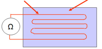
The strain gauge A strain gauge is composed of a resistive track and a deformable support. | |
Resistive track | Deformable body |
| |
Body deformation | |
| |
| |
| |
The Wheatstone Bridge
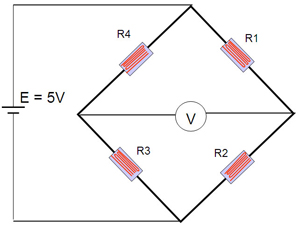
To measure the change in force, the change in resistance of the strain gauges is measured. To carry out this measurement, we use an electrical arrangement called a Wheatstone bridge as shown opposite. This circuit is in fact composed of 4 strain gauges placed in parallel in order to have a better linearity of the measurement.
Powered under constant voltage, the variation of the strain gauges varies the voltage measured by the Voltmeter on the diagram above. The value measured by V is proportional to the variation of the strain gauges according to the following formula:
V = (E x (R1 / (R1 + R4)) - E x (R2 / (R2 + R3))
Torque Measurement
Torque can be divided into two major categories, either static or dynamic. The methods used to measure torque can be further divided into two more categories, either reaction or in-line. Understanding the type of torque to be measured, as well as the different types of torque sensors that are available, will have a profound impact on the accuracy of the resulting data, as well as the cost of the measurement.
In a discussion of static vs. dynamic torque, it is often easiest start with an understanding of the difference between a static and dynamic force. To put it simply, a dynamic force involves acceleration, were a static force does not.
The relationship between dynamic force and acceleration is described by Newton’s second law; F=ma (force equals mass times acceleration). The force required to stop your car with its substantial mass would a dynamic force, as the car must be decelerated. The force exerted by the brake caliper in order to stop that car would be a static force because there is no acceleration of the brake pads involved.
Torque is just a rotational force, or a force through a distance it is considered static if it has no angular acceleration. The torque exerted by a clock spring would be a static torque, since there is no rotation and hence no angular acceleration. The torque transmitted through a cars drive axle as it cruises down the highway (at a constant speed) would be an example of a rotating static torque, because even though there is rotation, at a constant speed there is no acceleration.
The torque produced by the car’s engine will be both static and dynamic, depending on where it is measured. If the torque is measured in the crankshaft, there will be large dynamic torque fluctuations as each cylinder fires and its piston rotates the crankshaft.
If the torque is measured in the drive shaft it will be nearly static because the rotational inertia of the flywheel and transmission will dampen the dynamic torque produced by the engine. The torque required to crank up the windows in a car would be an example of a static torque, even though there is a rotational acceleration involved, because both the acceleration and rotational inertia of the crank are very small and the resulting dynamic torque (Torque = rotational inertia x rotational acceleration) will be negligible when compared to the frictional forces involved in the window movement
Torque is measured by either sensing the actual shaft deflection caused by a twisting force, or by detecting the effects of this deflection. The surface of a shaft under torque will experience compression and tension. To measure torque, strain gage elements usually are mounted in pairs on the shaft, one gauge measuring the increase in length (in the direction in which the surface is under tension), the other measuring the decrease in length in the other direction.
Early torque sensors consisted of mechanical structures fitted with strain gages. Their high cost and low reliability kept them from gaining general industrial acceptance. Modern technology, however, has lowered the cost of making torque measurements, while quality controls on production have increased the need for accurate torque measurement.
Torque Applications
Applications for torque sensors include determining the amount of power an engine, motor, turbine, or other rotating device generates or consumes. In the industrial world, ISO 9000 and other quality control specifications are now requiring companies to measure torque during manufacturing, especially when fasteners are applied. Sensors make the required torque measurements automatically on screw and assembly machines, and can be added to hand tools. In both cases, the collected data can be accumulated on data loggers for quality control and reporting purposes.
Other industrial applications of torque sensors include measuring metal removal rates in machine tools; the calibration of torque tools and sensors; measuring peel forces, friction, and bottle cap torque; testing springs; and making biodynamic measurements.

