UNIT 2
OPTICS
INTERFERENCE
Interference in light waves occurs whenever two or more waves overlap at a given point.
TYPES OF INTERFERENCE
Interference of light waves can be either constructive interference or destructive interference.
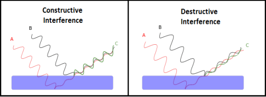
Figure 1
We know that the superposition of two mechanical waves can be constructive or destructive. In constructive interference, the amplitude of the resultant wave at a given position or time is greater than that of either individual wave, whereas in destructive interference, the resultant amplitude is less than that of either individual wave.
Light waves also interfere with each other. Fundamentally, all interference associated with light waves arises when the electromagnetic fields that constitute the individual waves combine.
If two light bulbs are placed side by side, no interference effects are observed because the light waves from one bulb are emitted independently of those from the other bulb. The emissions from the two light bulbs do not maintain a constant phase relationship with each other over time. Light waves from an ordinary source such as a light bulb undergo random phase changes in time intervals less than a nanosecond.
Therefore, the conditions for constructive interference, destructive interference, or some intermediate state are maintained only for such short time intervals. Because the eye cannot follow such rapid changes, no interference effects are observed. Such light sources are said to be incoherent.
COHERENT SOURCES
Two sources are said to be coherent when the waves emitted from them have the same frequency and constant phase difference.
Interference from such waves happen all the time, the randomly phased light waves constantly produce bright and dark fringes at every point. But, we cannot see them since they occur randomly. A point that has a dark fringe at one moment may have a bright fringe at the next moment. This cancels out the effect of the interference effect, and we see only an average brightness value. The interference is not said to be sustained since we cannot observe it.
Definition:- A predictable correlation of the amplitude and phase at any one point with other point is called coherence.

Figure 2
Two waves are said to be coherent, the waves must have
In case of convectional light, the property of coherence exhibits between a source and its virtual source where as in case of laser the property coherence exists between any two of more light waves.
There are two types of coherence
i) Temporal coherence
ii) Spatial coherence
TEMPORAL COHERENCE (OR LONGITUDINAL COHERENCE):-
The predictable correlation of amplitude and phase at one point on the wave train w .r. t another point on the same wave train, then the wave is said to be temporal coherence
To understand this, let us consider two points P1 and P2 on the same wave train, which is continuous as in shown in figure.
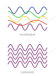
Figure 3
Suppose the phase and amplitude at any one point is known, then we can easily calculate the amplitude and phase for any other point on the same wave train by using the wave equation
y= a sin ( (ct-x))
Where ‘a’ is the amplitude of the wave and ‘x’ is the displacement of the wave at any instant of time‘t’.
SPATIAL COHERENCE (OR TRANSVERSE COHERENCE)
The predictable correlation of amplitude and phase at one point on the wave train w. r .t another point on a second wave, then the waves are said to be spatial coherence (or transverse coherence)

Figure 4
CONDITIONS OF INTERFERENCE
In a sustained interference pattern, the position of maximum and minimum intensity regions remains constant with time. To obtain the sustained interference, the following conditions are required:
FRESNEL’S BI-PRISM
The Fresnel double prism or biprism consists of two thin prisms joined at their bases, as shown in Figure 5. A single cylindrical wavefront impinges on both prisms. The top portion of the wavefront is refracted downward, and the lower segment is refracted upward. In theregion of superposition, interference occurs. Here, again, two virtual sources S1 and S2exist, separated by a distance a, which can be expressed in terms of the prism angle, where D>>d. The expression for the separation of the fringes is the same as before.

where (D = a + b) is distance of the sources from the eyepiece.
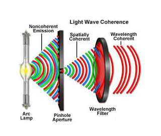
Figure5
Light from monochromatic source is made to fall on a thin slit mounted vertically on a rigid optical bench fitted with a scale. The biprism and the screen (in this case an eye piece) are also mounted vertically. The eye piece can be moved in the plane perpendicular to the axis of bench using a micrometer based translation stage.
Applications of Fresnel's Biprism
Fresnel biprism can be used to determine the wavelength of a light source (monochromatic), thickness of a thin transparent sheet/ thin film, refractive index of medium etc.
Determination of wave length of light
As expression for fringe width is

Biprism can be used to determine the wavelength of given monochromatic light using the expression.

Determination of fringe width β:
When the fringes are observed in the field view of the eyepiece, the vertical cross-wire is made to coincide with the centre of one of the bright fringes. the position of the eyepiece is read on the scale, say x°. The micrometer screw of the eyepiece is moved slowly and the number of the bright fringes N that pass across the cross-wire is counted. The position of the cross-wire is again read, say xN. The fringe width is then given by

Determination of ( d ):
The value of d can be determined as follows. The deviation δ produced in the path of a ray by a thin prism is given by
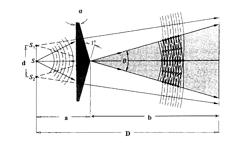
where α is the refracting angle of the prism. For the figure, it is seen δ=θ∕2. Since d is very small, we can also write d = aθ


Interference Fringes with white light:
In the biprism experiment if the slit is illuminated by white light the interference pattern consists of a central white fringe flanked on its both sides by a few coloured fringes and general illumination beyond the fringes. The central white fringe is the zero-order fringe.
With monochromatic light all the bright fringes are of the same colour and it is not possible to locate zero-order fringe. Therefore, in order to locate the zero-order fringe the biprism is to be illuminated by white light.
Lateral Displacement of Fringes
The biprism experiment can be used to determine the thickness of given thin sheet of transparent material such as glass or mica. If a thin transparent sheet is introduced in the path of one of the two interfering beams, the fringe system gets displaced towards the beam in whose path the sheet is introduced. By measuring of displacement, the thickness of the sheet can be determined.Suppose S1and S2are the virtual coherent monochromatic sources. The point O is equidistant from S1and S2, where we obtain the central bright fringe. Therefore, the optical path S1O=S2O. Let a transparent plate G of thickness t and refractive index n be introduced in the path of one of the beams(see figure 6). The optical path lengths S1O and S2O are now not equal and the central bright fringe shitsto P from O. The light waves from S1to P travel partly in air and partly in the sheet G: the distance travelled in air is (S1P –t) and that in the sheet is t.

Figure 6
The optical path
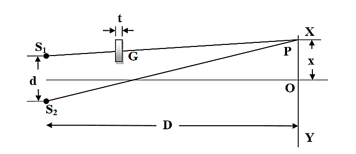
The optical path

The optical path difference at P is

since in the presence of the thin sheet, the optical path lengths S1P and S2P are equal and central zero fringe is obtained at P.

But according to the relation
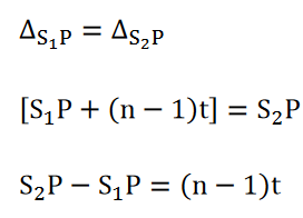
Where x is the lateral shift of the central fringe due to the introduction of the thin sheet.

Hence, the thickness of the sheet is

NEWTON’S RINGS
Newton’s Rings are the circular interference pattern first discovered by physicist Sir Isaac Newton in 1704. It is cosists of concentric bright and dark rings with the point of contact of lens and the glass plate as centre,
The fringes obtained by interference of light waves by using the following arrangement
When a Plano convex lens with large radius of curvature is placed on a plane glass plate such that its curved surface faces the glass plate, a wedge air film (of gradually increasing thickness) is formed between the lens and the glass plate. The thickness of the air film is zero at the point of contact and gradually increases away from the point of contact.
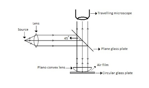
Figure7: Newton Ring Assembly
If monochromatic (means light with single wavelength) light is allowed to fall normally on the lens from a source 'S', then two reflected rays R1 (reflected from upper surface of the film) and R2 (reflected from lower surface of the air film) interfere to produce circular interference pattern. This interference pattern has concentric alternate bright and dark rings around the point of contact. This pattern is observed through traveling microscope.
MATHEMATICAL ANALYSIS OF NEWTON’S RING
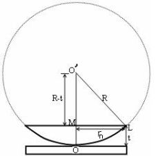
Figure8
(OL)2 =(O’M)2-(ML)2 ……….(1)
R2=(R-t)2 +rn2
R2=R2 +t2-2Rt +rn2
Radius is large as compared to the thickness
so t2 is neglected as t2<< R2
R2=R2 +-2Rt +rn2
2Rt =rn2
Thickness of the film t =rn2 /2R ……….(2)
THEORY OF FRINGES:
The effective path difference between the two reflected rays R1 and R2 for a wedge shaped film from equation
∆ = 2μtcos(r+θ) +λ/2 ……….(3)
If the light is incident normally on the lens,
r = 0 and near to point of contact θis small;
Therefore near point of contact, (r+θ) approaches to 0 and cos(r+θ)=cos0=1
Therefore
∆ = 2μt+λ/2 ……….(4)
Also At point of contact t = 0 therefore the effective path difference ∆ = λ/2
Which is odd multiple of λ/2 Therefore the Central fringe is dark.
BRIGHT FRINGE : CONDITION OF MAXIMA
For the condition of maxima the effective path difference
∆ = ±nλ
Using equation (4) ∆ = 2μt+λ/2 we have
2μt+λ/2= ±nλ
2μt = ± (2n-1)λ /2 ……….(5)
DIAMETER OF BRIGHT RINGS
we know by equation (2) t =rn2 /2R substitute in equation (5) we have
2μ (rn2 /2R) = ± (2n-1)λ /2
rn2 = ± (2n-1)λR /2μ
We know diameter D=2r and for nth fringe Dn=2rn
so we have Dn2=± 2(2n-1)λR /μ
Dn=
The medium enclosed between the lens and glass plate is if air therefore,  =1. The diameter of nth order bright fringe will be
D= n=0,1,2,3,4……. ……….(6)
The diameter of bright ring is proportional to square root of odd natural numbers
DARK FRINGE: CONDITION FOR MINIMA
For the condition of minima, the effective path difference
∆ =± (2n+1)λ /2
2μt+λ/2 =± (2n+1)λ /2
2μt= ±nλ ……….(7)
it is clear that for particular dark or bright fringe t should be constant.
Every fringe is the locus of points having equal thickness. Hence the fringes are circular in shape.
DIAMETER OF DARK RINGS
we know by equation (2) t =rn2 /2R substitute in equation (7) we have
2μ (rn2 /2R )=nλ
rn2=nλR/ μ
We know diameter D=2r and for nth fringe Dn=2rn
so we have Dn2= 4nλR/ μ
Dn= 
The medium enclosed between the lens and glass plate is if air therefore,  =1. The diameter of nth order bright fringe will be
Dn=  n=0,1,2,3,4……. ……….(8)
The diameter of dark ring is proportional to square root of natural numbers.
SPACING BETWEEN FRINGES
The Newton’s rings are not equally spaced because the diameter of ring does not increase in the same proportion as the order of ring and rings get closer and closer as ‘n’ increases.
For example the diameter of dark ring is given by Dn=  where n=0,1,2,3,4…….
D3 - D2 = -
-  = (
= ( -
- )
) = 0.635
D7 – D6 = -
-  = (
= ( -
- )
) = 0.392
D10– D9 = -
-  = (
= ( -
- )
) = 0.324
From above result we conclude that the fringe width reduces with increase in n.
APPLICATION OF NEWTON’S RING
The diameter of the nth order ring is calculated by subtracting the left and right side position of the microscope. As we know that the square of diameter of nth dark ring is

Therefore the square of diameter of (n+p)th ring is

Subtracting both the above equation ………...(9)
Therefore
 .............(10)
2. Determination of Refractive Index of liquid
In order to determine the refractive index of liquid the Newton’s ring experiment is first performed for the air medium and the difference in the square of the diameter of (n+p)th and nth dark ring is found as discussed above.  ………….(11)
After this few drops of liquid of μrefractive index is placed on the glass plate. The plano-convex lens is then placed on the glass plate, as a result a film of liquid is formed between the lens and the plate.
The difference in the square of the diameter of (n+p)th and nth dark ring is again calculated in the same manner for the liquid medium.
 …..….(12)
Dividing equation 2.29 by 2.30, we get
 …….….(13)
3. Newton’s ring with white light
If the monochromatic source is replaced by the white light, dark and bright fringes are not produced. Because the diameter of the rings depends upon wavelength and it is proportional to the square root of wavelength.
If If the monochromatic source is replaced by the white light superposition of rings take place due to different wavelength. Few coloured rings are seen around dark centre later illumination is seen in the field of view. As shown in below figure.
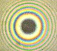
Figure9
Example: In a Newton’s rings experiment the diameter of the 15th ring was found to be 0.59 cm and that of the 5th ring is 0.336 cm. If the radius of curvature of the lens is 100 cm, find the wave length of the light.
Solution:
The given data are
Diameter of Newton’s 15th ring (D15) = 0.59 cm = 0.59×10⁻² m
Diameter of Newton’s 5th ring (D5) = 0.336 cm = 0.336 × 10⁻² m
Radius of curvature of lens (R) = 100 cm = 1 m
Wave length of light (λ) = ?
Here m is difference between rings = 15-5=10
λ = D2n+m - D2n / 4mR
λ = (0.59×10⁻² )2- (0.336 × 10⁻²)2 / 4 x 10 x 1
λ = 0.3481 x10⁻⁴ – 0.112896 x10⁻⁴ / 40
λ =0.00588 x 10⁻⁴ m
λ =5880 x 10-10 m
λ =5880Å
Huygens' Principle
In 1678 Huygens proposed a model where each point on a wavefront may be regarded as a source of waves expanding from that point.
Every point on a wavefront is a source of wavelets that spread out in the forward direction at the same speed as the wave itself. The new wavefront is a line tangent to all of the wavelets.
So Huygens’s Principle states that every point on a wavefront is a source of wavelets, which spread forward at the same speed.

Figure 10
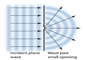
The expanding waves may be demonstrated in a ripple tank by sending plane waves toward a barrier with a small opening. If waves approaching a beach strike a barrier with a small opening, the waves may be seen to expand from the opening.
Huygens-Fresnel Theory:
According to Huygens’s wave theory of light, each progressive wave produces secondary waves, the envelope of which forms the secondary wave front.
In figure 11 (a). S is a source of monochromatic light and MN is a small aperture. XY is the screen placed in the path of light. AB is the illuminated portion of the screen and above A and below B is the region of the geometrical shadow. Considering MN as the primary wave front. According to Huygens’s construction, if secondary wave fronts are drawn, one would expect encroachment of light in the geometrical shadow. Thus, the shadows formed by small obstacles are not sharp. This bending of light round the edges of an obstacle or the encroachment of light withinthe geometrical shadow is known as diffraction. Similarly, if an opaque obstacle MN is placed in the path of light [Figure 11 (b)], there should be illumination in the geometrical shadow region AB also. But the illumination in the geometrical shadow of an obstacle is not commonly observed because the light sources are not point sources and secondly the obstacles used are of very large size compared to the wavelength of light. If a shadow of an obstacle is cast by an extended source, say a frosted electric bulb, light from every point on the surface of the bulb forms its own diffraction pattern (bright and dark diffraction bands) and these overlap such that no single pattern can be identified. The term diffraction is referred to such problems in which one considers the resultant effect produced by a limited portion of a wave front.
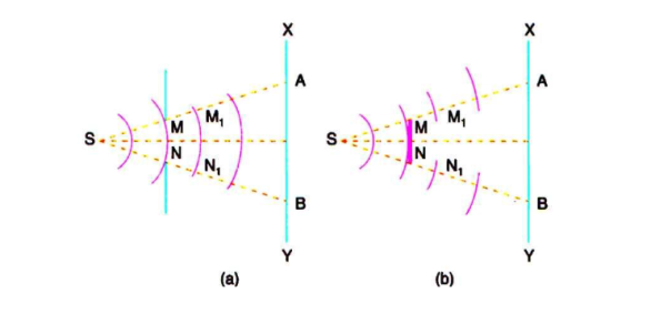
Figure 11
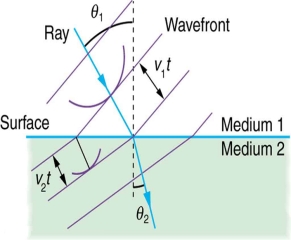
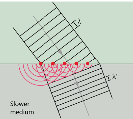
Huygens' principle provides a convenient way to visualize refraction. If points on the wavefront at the boundary of a different medium serve as sources for the propagating light, one can see why the direction of the light propagation changes.
The law of refraction can be explained by applying Huygens’s principle to a wavefront passing from one medium to another (see Figure 12). Each wavelet in the figure was emitted when the wavefront crossed the interface between the media. Since the speed of light is smaller in the second medium, the waves do not travel as far in a given time, and the new wavefront changes direction as shown. This explains why a ray changes direction to become closer to the perpendicular when light slows down.
|
|
(a) | (b) |
Figure 12
If we pass light through smaller openings, often called slits, we can use Huygens’s principle to see that light bends as sound does. The bending of a wave around the edges of an opening or an obstacle is called diffraction.
Diffraction is a wave characteristic and occurs for all types of waves. If diffraction is observed for some phenomenon, it is evidence that the phenomenon is a wave. Thus the horizontal diffraction of the laser beam after it passes through slits is evidence that light is a wave.
Diffraction phenomena are part of our common experience. The luminous border that surrounds the profile of a mountain just before the sun rises behind it, the lightstreaks that one sees while looking at a strong source of light with half shut eyes and the colored spectra (arranged in the form of a cross) that one sees while viewing a distant source of light through a fine piece of cloth are all examples of diffraction effects.Augustine Jean Fresnel in 1815, combined in a striking manner Huygens' wavelets with the principle of interference and could satisfactorily explain the bending of light round obstacles and also the rectilinear propagation of light.
The phenomenon of interference may be grouped into two categories:
Fresnel Diffraction | Fraunhoffer diffraction |
1If the source of light and screen is at a finite distance from the obstacle, then the diffraction called Fresnel diffraction. | 1 If the source of light and screen is at infinite distance from the obstacle then the diffraction is called Fraunhoffer diffraction. |
2 The corresponding rays are not parallel. | 2 The corresponding rays are not parallel. |
3 The wavefronts falling on the obstacle are not plane. | 3 The wavefronts falling on the obstacle are planes. |
4 No convex lens is needed to converge spherical wavefronts. | 4 Plane diffracting wavefronts are converged by means of a convex lens to produce diffraction pattern. |
5 Fresnel diffraction patterns on flat surfaces. | 5 Fraunhoffer diffraction patterns on spherical surfaces. |
6 Diffraction patternsChange as we propagate them further ‘downstream’ of the source of scattering. | 6 Diffraction patternsShape and intensity of a Fraunhoffer diffraction pattern stay constant. |
7 To obtain Fresnel diffraction, zone plates are used. | 7 To obtain Fraunhoffer diffraction, the single-double plane diffraction grafting is used. |
8 Diffraction pattern move along the corresponding shift in the object. | 8 Diffraction pattern remains in a fixed position. |
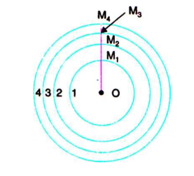
ABCD is a plane wave front perpendicular to the plane of the paper [Figure 13(a)] and P is an external point at a distance b perpendicular to ABCD. To find the resultant intensity at P due to the wave front ABCD, Fresnel's method consists in dividing the wave front into a number of half period elements or zones called Fresnel's zones and to find the effect of all the zones at the point P.
If spheres are constructed with P as centre and radii equal to b+λ/2. b+2λ/2. b+3 λ/2etc..they will cut out circular areas of radii OM1, OM2,OM3, etc.. on the wave front. These circular zones are called half period zones or half period elements.
Each zone differs from its neighbour by a phase difference of π or path difference of λ /2. Thus the secondary waves starting from the point O and M1and reaching P will have a phase difference of π or a path difference λ /2. A Fresnel half period zone with respect to an actual point P is a thin annular zone of the primary wave front in which the secondary waves from any two corresponding points of neighbouring zones differ in path by λ /2.
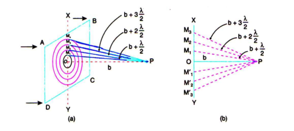
Figure 13
In Figure 13 (b) O is the pole of the wave front XY with reference to the external point P. OP is perpendicular to XY.
In Figure 14, 1.2.3 etc.are the half period zones constructed on the primary wave front XY. OM1 is the radius of the first zone. OM2 is the radius of the second zone and so on. P is the point at which the resultant intensity has to be calculated.
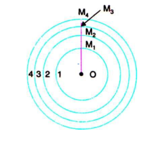
Figure 14

and

The area of the first half period zone is

.…..(1)
As λ is small, λ2 term is neglected. The radius of the first half period zone is,

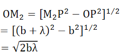
The radius of the second half period zone is,
 The area of the second half period zone

.…..(2)
Thus, the area of each half period zone is equal to πbλ.
Also the radii of the 1st, 2nd, 3td, etc. half period zones are ,
,  ,
, etc. Therefore, the radii are proportional to the square roots of the natural numbers. However, it should be remembered that the areas of the zones are not constant but are dependent on
(i) λ, the wavelength of light and
(ii) b, the distance of the point from the wave front.
The area of the zone increases with increase in the wavelength of light and with increase in the distance of the point P from the wave front.
As discussed in Fresnel's Assumptions the effect at a point will depend on
(i) the distance of P from the wave front,
(ii) the area of the zone and
(iii) the obliquity factor.
Here, the area of each zone is the same. The secondary waves reaching the point P are continuously out of phase and in phase with reference to the central or the first half period zone.
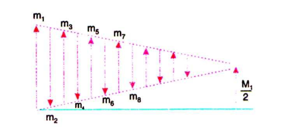
Let m1, m2, m3, etc. represent the amplitudes of vibration of the ether particles at P due to secondary waves from the 1st, 2nd, 3td, etc. half period zones (see Figure 15). As we consider the zones outwards from O, the obliquity increases and hence the quantities m1, m2, m3, etc. are of continuously decreasing order. Thus, m1is slightly greater than m2; m2is slightly greater than m3and so on. Due to the phase difference of π between any two consecutive zones, if the displacements of the ether particles due to odd numbered zones are in the positive direction, then due to the even numbered zones the displacement will be in the negative direction at the same instant. As the amplitudes are of gradually decreasing magnitude, the amplitude of vibration at P due to any zone can be approximately taken as the mean of the amplitudes due to the zones preceding and succeeding it.

The resultant amplitude at P, at any instant is given by,

If n is even, the last quantity is -mn.
If the whole wave front ABCD is unobstructed, the number of half period zones that can be constructed with reference to the point P is infinite i.e. n →∞. As the amplitudes are of gradually diminishing order, mn and mn-1, tend to be zero.Therefore, the resultant amplitude at P due to the whole wave front
A =  ………….(3)
The intensity at a point is proportional to the square of the amplitude.
I =  ………….(4)
Thus, the intensity at P is only one-fourth of that due to the first half period zone alone. Here, only half the area of the first half period zone is effective in producing the illumination atthe point P. A small obstacle of the size of half the area of the first half period zone placed at will screen the effect of the whole wave front and the intensity at P due to the rest of the wave front will be zero. While considering the rectilinear propagation of light, the size of the obstacle used is far greater than the area of the first half period zone and hence the bending effect of light round corners (diffraction effects) cannot be noticed.
In the case of sound waves, the wavelengths are far greater than the wavelength of light, and hence the area of the first half period zone for a plane wave front of sound is very large. If the effect of sound at a point beyond an obstacle is to be shadowed, an obstacle of very large size has to be used to get no sound effect. if the size of the obstacles placed in the path of light is comparable to the wavelength of light, then it is possible to observe illumination in the region of the geometrical shadow also. Thus, rectilinear propagation of light is only approximately true.
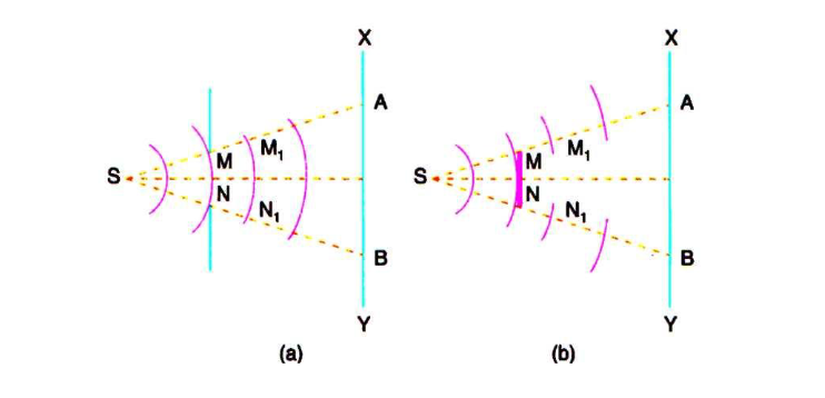
Figure 15
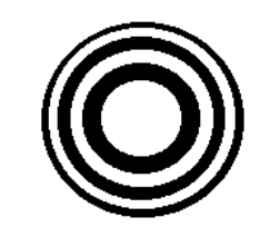
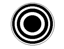
A zone plate is an optical device, which works on the principle of Fresnel’s zone. InFresnel’s zones, the effect at a point due to alternate zones cancels each other. If the effect ofeither even or odd zones is blocked at that point, then the net effect due to alternate zoneshaving a path difference of has a maximum value. A plate, which allows only one set ofalternate zones of the wavefront to pass through it, is called a zone plate.
The radius of the zones is proportional to , where n = 1, 2, 3, etc. This property isused in the construction of a zone plate. On a drawing sheet, concentric circles are drawnwith the radii proportional to square root of natural numbers as shown in the following figure (16). The alternate zones are painted black. A photograph of the pattern is taken. We get ondeveloped negative a reduced pattern. This negative forms the zone plate. In this platealternate zones are transparent and allow light and the remaining alternate zones act asopaque region. There are two types of zone plates
(1)Positive zone plate and
(2) Negativezone plate as shown in figure (16 a) & (16 b).
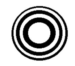
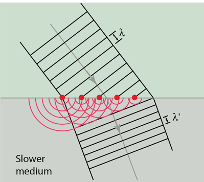
Figure (16 a) Positive zone plate Figure (16 b) Negative zone plate
Figure 16
THEORY OF ZONE PLATE
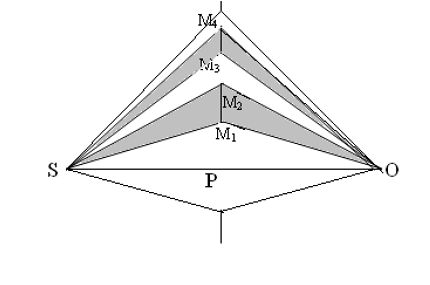
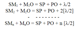
Let AB be an imaginary transparent plate perpendicular to the plane of the paper as shown in figure (17). Let ‘S’ be a point source of monochromatic light giving out spherical wave of wavelength ‘λ’. Draw SP perpendicular to the plane AB and produce it up to ‘O’. Let us assume that we want to find out the resultant effect at the point “O” on the screen placed perpendicular to the plane of the paper. With ‘P’ as centre, imagine the plate AB to be divided into circular half period zones with radii equal to PM1, PM2, PM3, etc., such that;
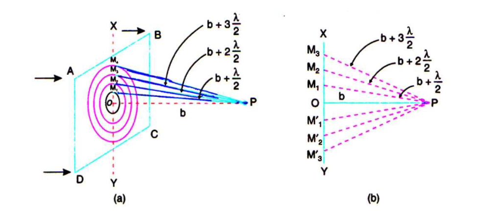
Figure 17
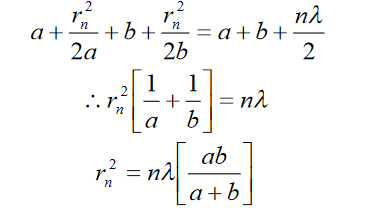
To determine the radius rn of the nth circle, consider the relation,

Let SP = a, PO = b, then we can write,
 ……….(1)
‘rn’ is very small compared to ‘a’ and hence by applying binomial theorem and neglecting the square and higher order term, we get the above equation.
Similarly,
 ……….(2)
Substituting for SMn and MnO, we get,
 ……….(3)
Since a, b and are constants,
 ……….(4)
It follows that the external radii of the various zones for given values of a and b are proportional to the square root of natural numbers.
Area of nth zone

……….(5)
Area of nth zone is independent of the order ‘n’. This means that for the given positions of the point source ‘S’ and its image ‘O’, the area of all the zones remains practically constant. But, as the amplitude at ‘O’ m1, m2, m3, etc., due to various zones decrease very slightly with the order of the zones and are alternately in opposite phase, the resultant amplitude is given by,
 ……….(6)
If monochromatic light from ‘S’ is allowed to fall on this zone plate and the emergentlight is received on a screen, then for a certain value of ‘b’, the hypothetical half-periodelements of the incident wavefront may coincide with the actual elemental areas of the plate.In such a case if even numbered elements are made opaque, then the resultant amplitude isgiven by,
A =m1 + m3 +m5 +…… ……….(7)
This value is many times greater than that due to all the zones. This means that a zone plate has the focusing action. Under these conditions, ‘O’ can be said to be the image of ‘S’. Equation (4) can be arranged in the following form.
 ……….(8)
Comparing equation (8) with the lens formula,
 ……….(9)
We have
 ……….(10)
Equation (10) gives the value of primary or first order focal length of the zone plate.
MULTIPLE FOCI OF A ZONE PLATE
When a =, the focal length of the zone plate is equal to ‘b’, and hence
 ……… (11)
For this focal length each actual zone of the plate contains one half-period elementand the focal point O1 is called the first order focal point, the intensity of the image ismaximum being proportional to .
.
If each zone contains three half-period elements with respect to some other point ‘O2’, nearer to the plate, then the resultant intensity at O2 is given by,
The rays transmitted through each successive transparent zone have a mean pathdifference of 3. Hence, O2 is known as the third order focal point.As the first transparent zone contains three half-period elements all of equal area, we can write,
Hence, the second focal length of the zone plate is given by,
Similarly, we can show that the third focal length of the zone plate is given by,

In general, the focal length of various foci of the zone plate can be given by the formula,

Where, p = 0, 1, 2, 3, etc.
Comparison between a zone plate and a convex lens
Zone plate | Convex lens |
1) Zone plate works on the phenomenon of diffraction | (1) Convex lens works on the phenomenon of refraction of light. |
(2) Odd zone transparent plate produces real image on the opposite side of the plate. | (2) Convex lens produces real image of the object on the other side of the lens |
(3) It shows chromatic aberration as the focal length depends on the wavelength | (3) It shows chromatic aberration as the focal length depends on the wavelength |
(4) For a given wavelength, zone plate has different focal lengths given by equation.
| (4) A convex lens has a single focal length for a given wavelength given by the formula.
|
(5)Intensity of the image decreases with the order of focal length | (5) Intensity does not depend on the focal length. |
(6)In a zone plate, the red focus is nearer the plate than the violet focus, hence,fr fv | (6) In a lens the violet focus is nearer than the red focus, hence, fv fr |
Diffraction
When the light falls on the obstacle whose size is comparable with the wavelength of light then the light bends around the obstacle and enters in the geometrical shadow. This bending of light is called diffraction.
FRAUNHOFFER DIFFRACTION AT SINGLE SLIT
The adjacent figure represents a narrow slit AB of width ‘e’. Let a plane wavefront of monochromatic light of wavelength ' ' is incident on the slit. Let the diffracted light be focused by means of a convex lens on a screen. According to Huygen Fresnel, every point of the wavefront in the plane of the slit is a source of secondary wavelets. The secondary wavelets traveling normally to the slit i.e., along OP0are brought to focus at -+
azP0by the lens. Thus P0is a bright central image. The secondary wavelets traveling at an angle ' ' are focused at a point P1on the screen.
The intensity at the point P1is either minimum or maximum and depends upon the path difference between the secondary waves originating from the corresponding points of the wavefront.
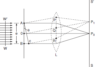
Figure 18
Theory:
In order to find out the intensity at P1, draw a perpendicular AC on BR.
The path difference between secondary wavelets from A and B in direction θ is BC i.e,

So, the phase difference,


Let us consider that the width of the slit is divided into ‘n’ equal parts and the amplitude of the wave from each part is ‘a’.
So, the phase difference between two consecutive points
 ........... (1)
Then the resultant amplitude R is calculated by using the method of vector addition of amplitudes
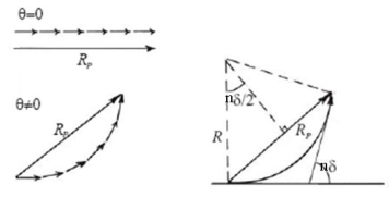
Figure 19
The resultant amplitude of n number of waves having same amplitude 'a' and having common phase difference of ' ' is
' is
 ................... (2)
Substituting the value of  in equation (2)
R = a  ................... (3)
Substituting =
=  .esinθ in equation (3)


As  is small value; sin
R = n
andna = A
Therefore
R =A ................... (4)
Therefore, the Intensity is given by
I =R2 = A2  ................... (5)
Case (i): Principal Maximum:
Eqn (4) takes maximum value for
 = 0
= 0
 =
=  .esinθ = 0
sinθ = 0 or θ=0
The condition
The condition θ=0 means that this maximum is formed by the secondary wavelets which travel normally to the slit along OP0and focus at P0. This maximum is known as “Principal maximum”.
Intensity of Principal maxima


Therefore
Imax= R2max = A2
Case (ii): Minimum Intensity positions:
Equation (3) takes minimum values for sin The values of '
 ' which satisfy sin
 are
are


 where
where ………...(6)
In the above equation (6) n = 0is not applicable because corresponds to principal maximum. Therefore, the positions according to equation (6) are on either side of the principal maximum.
Case (iii): Secondary maximum:
In addition to principal maximum at  = 0, there are weak secondary maxima between minima positions. The positions of these weak secondary maxima can be obtained with the rule of finding maxima and minima of a given function in calculus. So, differentiating equation (5) and equating to zero, we have
 =
=  (A2
(A2  ) =0
) =0
 = 2A2
= 2A2 (
( )(
)( =0
=0
A2  0;
0;  =0
=0
Because  =0 correspond to minima positions
 =0
=0
 ………... (7)
The values of ' ' satisfying the equation (7) are obtained graphically by plotting the curves
  and
and  on the same graph.
The points of intersection of the two curves gives the values of  which satisfy equation (7).
The points of intersections are

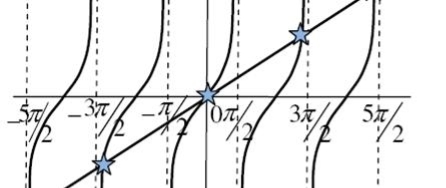
Figure20
But  , gives principal maximum, substituting the values of
  in equation (5), we get


and so on.
From the above expressions, Imax, I1, I2,I3… it is evident that most of the incident light is concentrated at the principal maximum.
INTENSITY DISTRIBUTION GRAPH
A graph showing the variation of intensity with ' ' is as shown in the adjacent figure
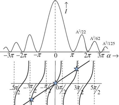
Figure21
