Unit - 3
Analog signal transmission and reception
- It is a process through which audio, video, image or text information is added to an electrical or optical carrier signal that is to be transmitted over a telecommunication or electronic medium.
- It enables the transfer of information on an electrical signal to a receiver that is capable of demodulating the signal to extract the blended information.
- It is primarily used in telecommunication technologies that require the transmission of data via electrical signals.
- It is considered the backbone of data communication as it enables the use of electrical and optical signals as information carriers.
- This is done by altering the periodic waveform or the carrier.
- This comprises of its amplitude, frequency and phase.
- Modulation has three different types:
- Amplitude Modulation (AM): Amplitude of the carrier is modulated.
- Frequency Modulation (FM): Frequency of the carrier is modulated.
- Phase Modulation (PM): Phase of the carrier is modulated.
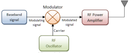
Fig.1: Modulation
Demodulation (downward frequency translation)
- It is the process of extracting the original information-carrying signal from a modulated carrier wave.
- A demodulator is an electronic circuit that is mainly used to recover the information from the modulated carrier wave.
- There are different types of demodulators.
- The output signal via demodulator may be sound, images or binary data.
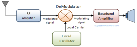
Fig.2: Demodulation
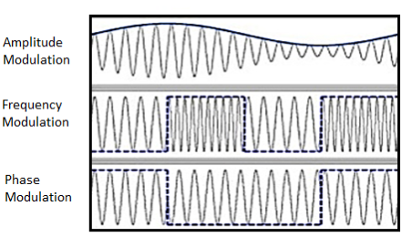
Fig.3: Demodulated Output
Necessity of Modulation: -
1>. Antenna height reduces
2>. Avoids mixing of signal
3>. Increases the range of communication [ In Kilometres]
4>. Multiplexing of signals is possible
5>. Improves quality of reception of signal.
1>. Antenna height Reduces: - Antenna theory specifies that the height of the antenna required for radiation of radio waves is a function of wavelength of the frequency fed at the i/p of the antenna. Antenna height must be multiple of (d/4),
Where ‘d’ is the wavelength.
d = speed of light / frequency of signal
d = c / f = 3 x 10⁸ / f
e.g.: Consider the voice as analog baseband signal with f = 4 KHz
d = 3 x 10⁸ / 4 x 10³
d = 75 x 103 m
d = 75 km
Height of antenna required is d / 4
= 75 km / 4 = 18.75 km
Q. Practically you cannot build the antenna of 18.7 km height. Consider this voice signal of 4 kHz frequency is used to modulate the carrier signal of 2 MHz frequency.
F = 2 MHz
D = c / f = 3 x 10⁸ / 2 x 106 = 150 m
Minimum height of antenna required = d / 4 = 150 / 4 = 37.5 m
Therefore, antenna height required for radio communication reduces from 75 km to 37.5 meters due to modulation.
2>. Increase range of communication: - The frequency of baseband signal is low. At low frequency the signal radiation from antenna is poor or weak. Due to this reason the signal gets attenuated and can’t travel long distance when it is transmitted.
Attenuation of the transmitted signal reduces when the frequency is increased.
Thus, modulation increases the frequency of the signal to be radiated. Thus, increase in frequency increases the range of communication.
Key Takeaways:
- Modulation increases the frequency of the signal to be radiated.
- Antenna height must be multiple of (d/4).
- Demodulation is the process of extracting the original information-carrying signal from a modulated carrier wave.
- Modulation is a process through which audio, video, image or text information is added to an electrical or optical carrier signal that is to be transmitted over a telecommunication or electronic medium.
The amplitude of the carrier signal varies in accordance with the instantaneous amplitude of the modulating signal. That is the amplitude of the carrier signal containing no information varies as per the amplitude of the signal containing information, at each instant.
Consider the following diagram
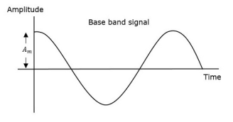
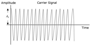
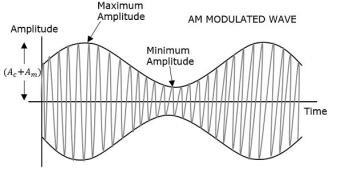
Fig.4: Amplitude Modulation
The first figure shows the modulating wave, which is the message signal. The next one is the carrier wave, which is a high frequency signal and contains no information. While, the last one is the resultant modulated wave.
It can be observed that the positive and negative peaks of the carrier wave are interconnected with an imaginary line. This line helps recreating the exact shape of the modulating signal. This imaginary line on the carrier wave is called as Envelope. It is the same as that of the message signal.
Therefore, we can say that Amplitude Modulation is the process of changing the amplitude of a relatively high frequency carrier signal in accordance with the amplitude of the modulating signal (Information). The carrier amplitude varies linearly by the modulating signal which usually consists of a range of audio frequencies. The frequency of the carrier is not affected.
The various forms of Amplitude Modulation are:
- Conventional Amplitude Modulation Full AM or Double Sideband Large carrier modulation (DSBLC) /Double Sideband Full Carrier (DSBFC)
- Double Sideband Suppressed carrier (DSBSC) modulation.
- Single Sideband (SSB) modulation
Generation of double side band (DSB) with carrier
DSBFC (Double Side Band Full Wave Carrier)
Time-Domain Representation
Let the modulating signal be,
m(t)=Am cos (2πfmt) --------------(1)
And the carrier signal be,
c(t)=Ac cos(2πfct) c(t) ---------------(2)
Where, Am and Ac are the amplitude of the modulating signal and the carrier signal respectively.
Fm and fc are the frequency of the modulating signal and the carrier signal respectively.
Then, the equation of Amplitude Modulated wave will be
s(t)= [Ac+ Am cos(2πfmt)] cos(2πfct) -------------------------- (3)
s(t) = [ Ac cos(2πfct) + Ac Am cos(2πfmt). Cos(2πfct)] ---------(4)
s(t) = Ac [1 + Am/Ac cos(2πfmt)] cos(2πfct) ----------- (5)
Here the modulation index µ = Am/Ac.
s(t) = Ac [1 + µ cos(2πfmt)] cos(2πfct) -------------- (6)
Modulation index
Let Amax and Amin be the maximum and minimum amplitudes of the modulated wave.
We will get the maximum amplitude of the modulated wave, when cos(2πfmt)
Is 1.
That is Amax=Ac + Am
We will get the minimum amplitude of the modulated wave, when cos(2πfmt)
Is -1.
That is Amin = Ac - Am
Amax + Amin = Ac + Am + Ac –Am = 2Ac
Ac = Amax + Amin/2
Similarly, Amax – Amin = Ac + Am – Ac +Am = 2Am
Am = Amax – Amin /2
Therefore
µ = Amax + Amin
Amax - Amin
Bandwidth:
Bandwidth is the difference between the highest and lowest frequencies of the signal.
BW = fmax – fmin
s(t) = Ac [1+ μcos(2πfmt)] cos(2πfct)
s(t) = Ac cos(2πfct) + Ac μcos(2πfmt) cos(2πfct)
s(t) = Ac cos(2πfct) + Ac μ/2 cos 2π (fc + fm) t + Ac μ/2 cos 2π (fc - fm) t
Hence, the amplitude modulated wave has three frequencies.
- Carrier frequency fc
- Upper sideband frequency fc+fm
- And lower sideband frequency fc−fm
Here, fmax=fc+fm and fmin=fc−fm
BW=fc+fm−(fc−fm)
BW=fc+fm−(fc−fm)
BW=2fm
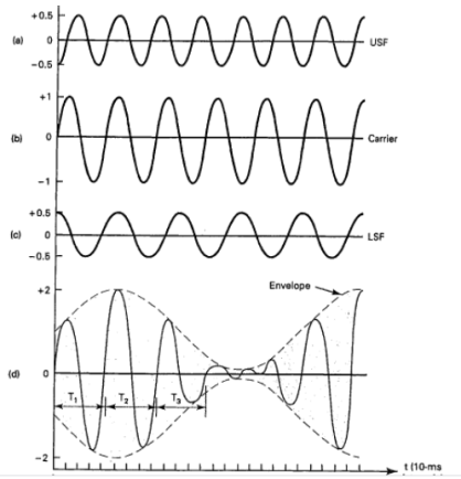
Fig.6: DSBFC
Power Calculation of AM
Consider the following equation of amplitude modulated wave.
s(t)=Ac cos(2πfct) +Acμ 2 cos[2π(fc+fm) t] + Acμ 2cos[2π(fc−fm) t] -------(1)
Power of AM wave is equal to the sum of powers of carrier, upper sideband, and lower sideband frequency components.
Pt=Pc+ PUSB+ PLSB
We know that the standard formula for power is
P = vrms 2 / R = (vm /  ) 2 /2
Where,
Vrms is the rms value of cos signal.
Vm is the peak value of cos signal.
The powers of the carrier, the upper and lower sideband is given by
Carrier power
Pc=(Ac/√2)2/R=Ac2/2R
Upper sideband power
PUSB=(Acμ/2√2)2/R= Ac2 μ2/ 8R
Similarly, for lower sideband power same as that of the upper side band power.
PLSB=(Acμ/2√2)2 /R
PLSB=Ac2μ2/R
Now, let us add these three powers in order to get the power of AM wave.
Pt=Ac2 /2R+Ac2μ2 /8R+Ac2μ2/8R
Pt= Ac2 /2R [ 1+μ2 /4+μ2 /4]
Pt=Pc (1+ μ 2/2 )
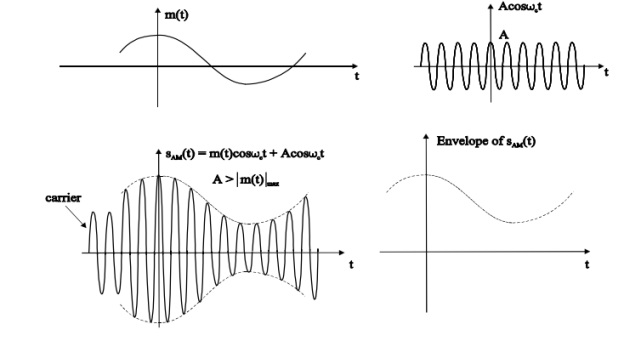
Fig.7: DSBFC
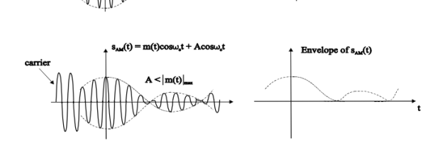
Fig.8: DSBFC
Problems
A modulating signal m(t)=10cos(2π×103t) m(t) is amplitude modulated with a carrier signal c(t)=50cos(2π×105t). Find the modulation index, the carrier power, and the power required for transmitting AM wave.
Solution
Given, the equation of modulating signal as
m(t)=10 cos(2π×103t) m(t)
We know the standard equation of modulating signal as
m(t)=Am cos(2πfmt) m(t)
By comparing the above two equations, we will get
Am=10 volts
And Frequency of modulating signal as
Fm=103Hz=1KHz
Given, the equation of carrier signal is
c(t)=50 cos(2π×105t))
The standard equation of carrier signal is
c(t)=Ac cos(2πfct) c(t)
By comparing these two equations, we will get
Amplitude of carrier signal as Ac=50 volts
And Frequency of carrier signal as fc=105Hz=100KHz
We know the formula for modulation index as
μ=Am/Ac
μ=10/50=0.2
Therefore, the value of modulation index is 0.2 and percentage of modulation is 20%.
The formula for Carrier power, Pc
Pc=Ac2 /2R
Assume R=1ΩR=1Ω and substitute Ac value in the above formula.
Pc= (50)2/2(1) =1250W
Therefore, the Carrier power, Pc is 1250 watts.
We know the formula for power required for transmitting AM wave is
Pt=Pc(1+μ2/2)
Pt=1250(1+(0.2)22) =1275W
Therefore, the power required for transmitting AM wave is 1275 watts.
Key Takeaways:
- Power of AM wave is equal to the sum of powers of carrier, upper sideband, and lower sideband frequency components.
Pt=Pc+ PUSB+ PLSB
2. Bandwidth is the difference between the highest and lowest frequencies of the signal.
BW = fmax – fmin
3. Modulation index is given by µ = Amax + Amin
Amax - Amin
Double side band with suppressed carrier (DSB-SC) and Single side band with suppressed carrier
DSBSC (Double Side Band Suppressed Carrier)
In DSBC modulation, the modulated wave consists of only the upper and lower side bands. Transmitted power is saved through the suppression of the carrier wave, but the channel bandwidth requirement is the same.
DSBSC modulators make use of the multiplying action in which the modulating signal multiplies the carrier wave. In this system, the carrier component is eliminated and both upper and lower side bands are transmitted. As the carrier component is suppressed, the power required for transmission is less than that of AM.
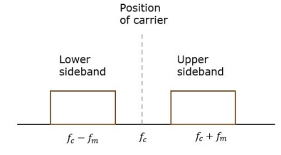
Fig.9: Position of carrier
Carrier is suppressed and base band is allowed for transmission.
If m(t) = Am cos(2πfmt) is the modulating signal and c(t) = Ac cos(2πfct) is the carrier signal then DSBSC wave s(t) is given by
s(t) = c(t) m(t) ------------------- (1)
s(t) =Am cos(2πfmt) Ac cos(2πfct) -------- (2)
s(t) = Am Ac cos(2πfmt) cos(2πfct) ------- (3)
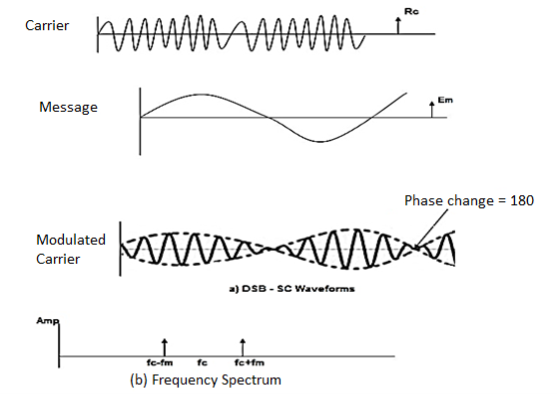
Fig.10: DSBSC
The figure shows the waveform and the frequency spectrum.
The envelope of a DSBSC modulated signal is therefore different from the message signal and the Fourier transform of s(t) is given by
S(f) = Ac/2[ M(f-fc) + M (f + fc)]
When base band signal m(t) is limited to interval –W<fc<W we find the spectrum S(f) of the DSBSC wave s(t) as shown in the figure. We see that there is a change in the scaling factor, the modulation process translates the spectrum of the base band signal by fc. The transmission bandwidth is same as AM.
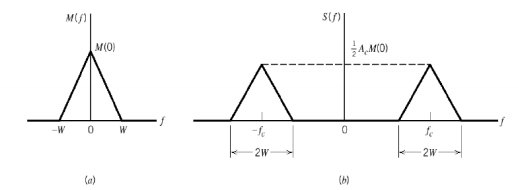
Fig.11: DSBSC transmission bandwidth
Bandwidth of DSBSC Wave
We know the formula for bandwidth (BW) is
BW=fmax−fmin
Consider the equation of DSBSC modulated wave.
s(t)=AmAccos(2πfmt) cos(2πfct) s(t)
s(t)=AmAc2cos[2π(fc+fm) t] +AmAc2cos[2π(fc−fm) t]
The DSBSC modulated wave has only two frequencies. So, the maximum and minimum frequencies are fc+ fm and fc− fm respectively.
i.e., fmax=fc+fm and fmin=fc−fm
BW=fc+fm−(fc−fm)
BW = 2fm
Thus, the bandwidth of DSBSC wave is same as that of AM wave and it is equal to twice the frequency of the modulating signal.
Power of DSBSC Wave
Consider the following equation of DSBSC modulated wave.
s(t)=AmAc2cos[2π(fc+fm) t] +AmAc2cos[2π(fc−fm) t]
Power of DSBSC wave is equal to the sum of powers of upper sideband and lower sideband frequency components.
Pt=PUSB+PLSB
We know the standard formula for power of cos signal is
P=vrms2 /R=(vm√2)2 /R
First, let us find the powers of upper sideband and lower sideband one by one.
Upper sideband power
PUSB=(AmAc/2√2)2/R=Am2Ac2 / 8R
Similarly, we will get the lower sideband power same as that of upper sideband power.
PLSB=Am2Ac2/8R
Now, let us add these two sideband powers in order to get the power of DSBSC wave.
Pt=Am2Ac2 /8R+Am2Ac2/8R
Pt=Am2Ac2 /4R
Therefore, the power required for transmitting DSBSC wave is equal to the power of both the sidebands.
Generation of DSBSC Waves:
Balanced Modulator (Product Modulator)
A balanced modulator consists of two standard amplitude modulators arranged in a balanced configuration so as to suppress the carrier wave as shown in the following block diagram. It is assumed that the AM modulators are identical, except for the sign reversal of the modulating wave applied to the input of one of them. Thus, the output of the two modulators may be expressed as,
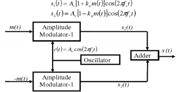
Fig.12: Balanced Modulator
Subtracting s2(t) from s1(t) we get
s(t) = s1(t) – s2(t)
s(t) = 2 ka m(t) cos(2πfct)
Hence, except for the scaling factor 2ka, the balanced modulator output is equal to the product of the modulating wave and the carrier.
Ring Modulator
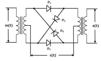
Fig.13: Ring Modulator
Operation
- In this diagram, the four diodes D1, D2, D3 and D4 are connected in the ring structure. Hence, this modulator is called as the ring modulator.
- Two center tapped transformers are used in this diagram. The message signal m(t) is applied to the input transformer, whereas, the carrier signals c(t) is applied between the two center tapped transformers.
- During the positive half cycle of the carrier signal, the diodes D1 and D3 are switched ON and the other two diodes D2 and D4 are switched OFF.
- In this case, the message signal is multiplied by +1.
- During the negative half cycle of the carrier signal, the diodes D2 and D4 are switched ON and the other two diodes D1 and D3 are switched OFF.
- In this case, the message signal is multiplied by -1. This results in 1800 phase shift in the resulting DSBSC wave.
From the above analysis, we can say that the four diodes D1, D2, D3 and D4 are controlled by the carrier signal.
If the carrier is a square wave, then the Fourier series representation of c(t) is given by
c(t) = 4 / π  n-1 / 2n -1 cos[2πfct(2n−1)]
We will get DSBSC wave s(t) which is just the product of the carrier signal c(t)) and the message signal m(t) i.e.,
s(t) = 4 / π  n-1 / 2n -1 cos[2πfct(2n−1)] m(t)
The ring modulator.
DSBSC modulators are known as product modulators as they produce the output, which is the product of two input signals.
Balanced Modulator using Non-linear resistance
- The DSBSC generation using balanced modulator based on nonlinear resistance characteristics of diode is shown in the figure below.
- The diode in the balanced modulator uses the nonlinear resistance property for producing modulated signals.
- Carrier voltage is applied in phase at both the diodes, while modulating voltage appears 180° out of phase at the diode inputs as they are at opposite ends of a center- tapped transformer.
- The modulated output currents of the two diodes are combined in the center tapped primary of the output transformer, which then gets subtracted.
- The output of the balanced modulator contains two sidebands and sum of the harmonic components.
As indicated in the Figure, the input voltage at diode D1 is vc+vm and input voltage at diode D2 is vc−vm.
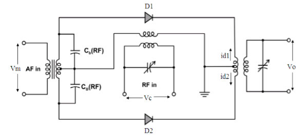
Fig.14: Balanced Modulator using Non-linear resistance
The primary current of the output transformer is i1=id1−id2.
Where,
Id1=a+ b(vc+vm) + c(vc+vm)2
Id2=a+ b(vc−vm) +c(vc−vm)2
Thus, we get,
i1= id1−id2=2bvm+4cvmvc
The modulating and carrier voltage are represented as,
vm=Vmsinωmt and vc=Vcsinωct
Substituting for vm and vc and simplifying, we get,
i1=2bVmsinωmt+4cmVc/2cos(ωc−ωm)t−4cmVc/2cos(ωc+ωm)t
The output voltage v0 is proportional to primary current i1 and assume constant of proportionality as α, which can be expressed as,
v0=αi1=2αbVmsinωmt+4αcmVc/2cos(ωc−ωm)t−4αcmVc/2cos(ωc+ωm)t
Let P=2αbVmP and Q=2αcmVc2.
Thus, we have,
v0=Psinωmt+2Qcos(ωc−ωm)t−2Qcos(ωc+ωm)t
The above equation shows that carrier has been cancelled out, leaving only two
Sidebands and the modulating frequencies from the output is eliminated by the tuning of the output transformer, which results in the below equation of the generated DSBSC wave.
v0=2Qcos(ωc−ωm)t−2Qcos(ωc+ωm)t
Switching Modulator
.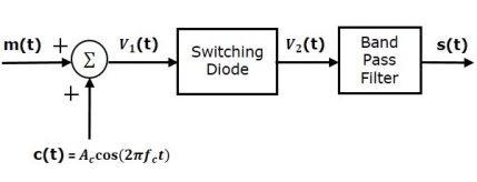
Fig.15 Switching Modulator
Switching modulator is similar to the square law modulator. The only difference is that in the square law modulator, the diode is operated in a non-linear mode, whereas, in the switching modulator, the diode has to operate as an ideal switch.
Let the modulating and carrier signals be denoted as m(t) and c(t)=Accos(2πfct). These two signals are applied as inputs to the summer (adder) block. Summer block produces an output, which is the addition of modulating and carrier signals. Mathematically, we can write it as
V1(t)=m(t)+c(t)=m(t)+Accos(2πfct)
This signal V1(t) is applied as an input of diode.
Assume, the magnitude of the modulating signal is very small when compared to the amplitude of carrier signal Ac. So, the diode’s ON and OFF action is controlled by carrier signal c(t). This means, the diode will be forward biased when c(t)>0 and it will be reverse biased when c(t)<0.
Therefore, the output of the diode is
V2(t)={V1(t)0 if c(t)>0
0 c(t) <0
We can approximate this as
V2(t)=V1(t)x(t)
Where, x(t) is a periodic pulse train with time period T=1fc

The Fourier series representation of this periodic pulse train is
x(t)=1/ 2+2π  n -1 / 2n-1 cos(2π(2n-1) fc(t)) ---------------------(1)
= ½ + 2/π cos(2πfct) -2 / 3 π cos(6πfct) + ………… ----------------(2)
Substituting V1(t) and x(t) we get
V2(t) = [m(t) + Ac cos(2πfct)] [½ + 2/π cos(2πfct) -2 / 3 π cos(6πfct) + …………] ---------------------------------------(3)
V2(t) = Ac/2 (1+ 4/πAc) m(t) cos(2πfct) + m(t)/2 + 2Ac/π cos (2πfct)- 2m(t)/3π cos (6 πfct)- 2A/3π cos(2πfct) cos(6πfct) + ………………………….
The 1st term of the above equation represents the desired AM wave and the remaining terms are unwanted terms. Thus, with the help of band pass filter, we can pass only AM wave and eliminate the remaining terms.
Therefore, the output of switching modulator is
s(t)=Ac2(1+(4π/Ac) m(t)) cos(2πfct)
We know the standard equation of AM wave is
s(t)=Ac[1+kam(t)] cos(2πfct) s(t)
Where, ka is the amplitude sensitivity.
By comparing the output of the switching modulator with the standard equation of AM wave, we will get the scaling factor as 0.5 and amplitude sensitivity ka as 4π/Ac.
SSB-SC
The process of suppressing one of the sidebands along with the carrier and transmitting a single sideband is called as Single Sideband Suppressed Carrier system or simply SSBSC. It is plotted as shown in the following figure.
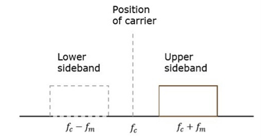
Fig.16 SSB
Carrier and sideband are suppressed and single sideband is allowed for transmission.
Let us consider the
Modulating signal
m(t)=Amcos(2πfmt)
Carrier signal
c(t)=Accos(2πfct)
Mathematically, we can represent the equation of SSB-SC wave as
s(t)=AmAc2cos[2π(fc+fm) t] for the upper sideband
Or
s(t)= AmAc2cos[2π(fc−fm) t] for the lower sideband
Bandwidth of SSB-SC Wave
We know that the DSB-SC modulated wave contains two sidebands and its bandwidth is 2fm. Since the SSB-SC modulated wave contains only one sideband, its bandwidth is half of the bandwidth of DSBSC modulated wave.
i.e., Bandwidth of SSBSC modulated wave =2fm/2=fm
Therefore, the bandwidth of SSB-SC modulated wave is fm and it is equal to the frequency of the modulating signal.
Power Calculations of SSB-SC Wave
Consider the following equation of SSBSC modulated wave.
s(t)=AmAc/2 cos[2π(fc+fm) t] for the upper sideband
Or
s(t)=AmAc/2 cos[2π(fc−fm) t] for the lower sideband
Power of SSB-SC wave is equal to the power of any one sideband frequency components.
Pt=PUSB=PLSB
We know power
P=vrms2 / R
=(vm/√2)2 / R
In this case, the power of the upper sideband is
PUSB=(AmAc/2√2)2 / R = Am2Ac2 /8R.
Similarly, for lower sideband power.
PLSB=Am2Ac2 / 8R
Therefore, the power of SSB-SC wave is
Pt=Am2Ac2 / 8R
Advantages
- Bandwidth or spectrum space occupied is lesser than AM and DSBSC waves.
- Transmission of more number of signals is allowed.
- Power is saved.
- High power signal can be transmitted.
- Less amount of noise is present.
- Signal fading is less likely to occur.
Disadvantages
- The generation and detection of SSBSC wave is a complex process.
- The quality of the signal gets affected unless the SSB transmitter and receiver have an excellent frequency stability.
Applications
- Power saving requirements and low bandwidth requirements.
- In land, air, and maritime mobile communications.
- Point-to-point communications.
- Radio communications.
- Television, telemetry, and radar communications.
- Military communications, such as amateur radio, etc.
Generation of SSB-SC
We can generate SSBSC wave using the following two methods.
- Frequency discrimination method
- Phase discrimination method
Frequency Discrimination Method
In this method the DSB signal is passed through band pass filter to generate SSB signal.
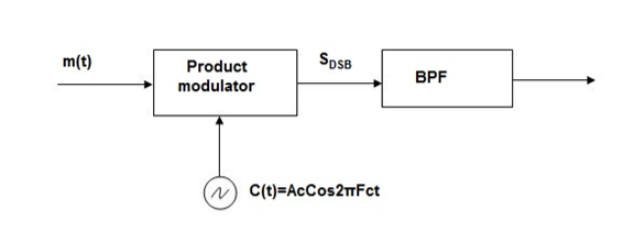
Fig.17 Frequency Discrimination method
The center frequency of the band pass signal decides whether USB or LSB signal is generated.
Suppose we want to transmit USB then using band pass filter with center frequency fc + w/2 we obtain the desired result as shown in the figure.
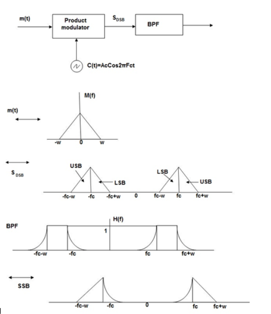
Fig.18: Resultant output
Phase Discriminated Method:
Consider the following block diagram of SSB-SC modulator using phase discrimination method.
.
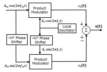
Fig.19 Phase Discriminated Method
- It consists of two product modulators, two −900 phase shifters, one local oscillator and one summer block.
- The product modulator produces an output, which is the product of two inputs.
- The −900 phase shifter produces an output, which has a phase lag of −900 with respect to the input.
- The local oscillator is used to generate the carrier signal.
- Summer block produces an output, which is either the sum of two inputs or the difference of two inputs based on the polarity of inputs.
The modulating signal
m(t) = Amcos(2πfmt) -----------------(1)
The carrier signal
c(t) = Accos(2πfct) -----------------------(2)
Which are directly applied as inputs to the upper product modulator. So, the upper product
Modulator produces an output, which is the product of these two inputs.
The output of upper product modulator is
s1(t)=AmAc cos(2πfmt) cos(2πfct) --------------------(3)
s1(t)=AmAc/2{cos[2π(fc+fm) t] +cos[2π(fc−fm) t]} -----------(4)
The modulating signal Am cos(2πfmt) and the carrier signal Ac cos(2πfct) are phase shifted by −900 before applying as inputs to the lower product modulator. So, the lower product modulator produces an output, which is the product of these two inputs.
The output of lower product modulator is
s2(t)=AmAc cos(2πfmt−900) cos(2πfct−900) ---------------(5)
s2(t)=AmAc sin(2πfmt) sin(2πfct) -------------------(6)
s2(t)=AmAc/2{cos[2π(fc−fm) t] −cos[2π(fc+fm) t]} ----------(7)
Add s1(t) and s2(t) in order to get the SSB-SC modulated wave s(t) having a lower sideband.
s(t)=AmAc/2{cos[2π(fc+fm) t] +cos[2π(fc−fm) t]} +AmAc/2{cos[2π(fc−fm) t] −cos[2π(fc+fm) t]} ----------------------------------(8)
s(t)=AmAc cos[2π(fc−fm) t] ------------------------(9)
Subtract s2(t) from s1(t) in order to get the SSBSC modulated wave s(t) having an upper sideband.
s(t)=AmAc/2{cos[2π(fc+fm) t] +cos[2π(fc−fm) t]} −AmAc/2{cos[2π(fc−fm) t] −cos[2π(fc+fm) t]} ---------------------------------------------------------(10)
s(t)=AmAc cos[2π(fc+fm) t] --------------------------(11)
Hence, by properly choosing the polarities of inputs at summer block, we will get SSB-SC wave having an upper sideband or a lower sideband.
Key Takeaways:
- We can generate SSBSC wave using the following two methods.
- Frequency discrimination method
- Phase discrimination method
2. The power of SSB-SC wave is Pt=Am2Ac2 / 8R
3. The process of suppressing one of the sidebands along with the carrier and transmitting a single sideband is called as Single Sideband Suppressed Carrier system or simply SSBSC.
4. The power of DSB-SC wave is Pt=Am2Ac2 /4R
5. In DSBC modulation, the modulated wave consists of only the upper and lower side bands. Transmitted power is saved through the suppression of the carrier wave, but the channel bandwidth requirement is the same.
Another type of modulation in continuous-wave modulation is Angle Modulation.
Angle Modulation is the process in which the frequency or the phase of the carrier
Signal varies according to the message signal.
The standard equation of the angle modulated wave is
s(t)=Ac cosθi(t)-------------------(1)
Where,
Ac is the amplitude of the modulated wave, which is the same as the amplitude of the carrier signal
θi(t) is the angle of the modulated wave
Angle modulation is further divided into frequency modulation and phase modulation.
- Frequency Modulation is the process of varying the frequency of the carrier signal linearly with the message signal.
- Phase Modulation is the process of varying the phase of the carrier signal linearly with the message signal.
3. Phase Modulation
In frequency modulation, the frequency of the carrier varies whereas, in Phase Modulation (PM), the phase of the carrier signal varies in accordance with the instantaneous amplitude of the modulating signal.
So, in phase modulation, the amplitude and the frequency of the carrier signal remains constant.
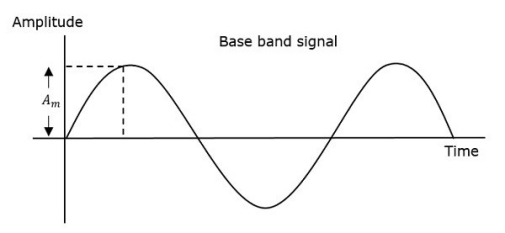
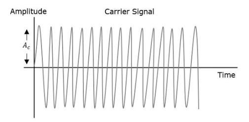
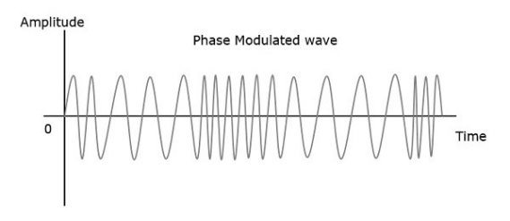
Fig 20 Angle Modulation
The phase of the modulated wave has infinite points, where the phase shift in a wave can take place. The instantaneous amplitude of the modulating signal changes the phase of the carrier signal. When the amplitude is positive, the phase changes in one direction and if the amplitude is negative, the phase changes in the opposite direction.
Representation
The equation for instantaneous phase ϕi in phase modulation is
ϕi=kpm(t)----------------------(1)
Where,
- Kp is the phase sensitivity
- m(t) is the message signal
The standard equation of angle modulated wave is
s(t)=Ac cos(2πfct+ϕi) ---------------------------------(2)
Substitute, ϕi value in the above equation.
s(t)=Ac cos(2πfct+kpm(t)) -----------------------------------(3)
This is the equation of PM wave.
If the modulating signal,
m(t)=Am cos(2πfmt) --------------------------------(4)
Then the equation of PM wave will be
s(t)=Ac cos(2πfct+βcos(2πfmt)) -----------------------------------(5)
Where,
- β = modulation index = Δϕ=kpAm
- Δϕ is phase deviation
Phase modulation is used in mobile communication systems, while frequency modulation is used mainly for FM broadcasting.
Bessel Function and its Mathematical Analysis
Time – Domain Expression:
Since the FM wave is a nonlinear function of the modulating wave, the frequency modulation is a nonlinear process.
Let us consider a single-tone sinusoidal message signal defined by
n(t) = An cos(2nƒnt) -----------------------(1)
The instantaneous frequency is
ƒ(t) = ƒc+kƒAn cos(2nƒnt) -----------------------(2)
= ƒc+∆ƒ cos(2nƒnt) -----------------------------(3)
∆ƒ = kƒAn
 = 2 πfct + 2πKf
  m cos (2 πfmt) dt -------------------(4)
= 2 πfct + 2πKf Am / 2πfm sin(2πfmt) --------------------(5)
= 2 πfct + Kf Am/fm sin(2πfmt) ------------------------(6)
= 2 πfct + β f sin(2πfmt) ---------------------------(7)
Where β = ∆ƒ/fm = Kf Am/fm = modulation index.
Therefore, the single-tone FM wave is expressed by
FM(t) = Ac cos[2nƒct + þƒ sin(2nƒnt)] ------------------------------(8)
This is the desired time-domain expression of the single-tone FM wave
Similarly, single-tone phase modulated wave may be determined where
PM(t) = Ac cos[2nƒct + kp An cos(2nƒnt)] -------------------------(9)
Or, PM(t) = Ac cos[2nƒct +þp cos(2nƒnt)] --------------------------(10)
þp = kpAn ---------------------------(11)
The frequency deviation of the single-tone PM wave is
FM(t) = Ac cos[2 πfct + β f sin(2πfmt)]-----------------(12)
Frequency Modulation
In amplitude modulation, the amplitude of the carrier signal varies, whereas in Frequency Modulation (FM), the frequency of the carrier signal varies in accordance with the instantaneous amplitude of the modulating signal.
Hence, in frequency modulation, the amplitude and the phase of the carrier signal remains constant.
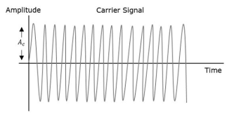
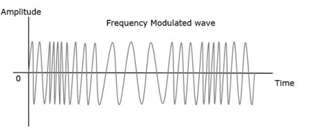
Fig 21 Frequency Modulation
- The frequency fi of the information signal controls the rate at which the carrier frequency increases and decreases. As with AM, fi must be less than fc. The amplitude of the carrier remains constant throughout this process.
- When the information voltage reaches its maximum value then the change in frequency of the carrier will have also reached its maximum deviation above the nominal value.
- Similarly, when the information reaches a minimum, the carrier will be at its lowest frequency below the nominal carrier frequency value.
- When the information signal is zero, then no deviation of the carrier will occur. The maximum change that can occur to the carrier from its base value fc is called the fc. This sets the dynamic range i.e. voltage frequency deviation, of the transmission. The dynamic range is the ratio of the largest and smallest analogue information signals that can be transmitted.
Representation:
The equation for instantaneous frequency fi in FM modulation is
Fi=fc+kfm(t)------------------------(1)
Where,
Fc is the carrier frequency
Kt is the frequency sensitivity
m(t) is the message signal
We know the relationship between angular frequency ωi and angle θi(t) as
ωi=dθi(t)/dt -------------------------(2)
2πfi=dθi(t)dt-------------------------(3)
θi(t)=2π  i dt -------------------------(4)
Substitute, fi value in the above equation.
θi(t)=2π  +k fm(t))dt-----------------(5)
θi(t)=2πfct+2πkf  (t)dt --------------------(6)
This is the equation of FM wave.
If the modulating signal is m(t)=Am cos(2πfmt) then the equation of FM wave will be
s(t)=Ac cos(2πfct+βsin(2πfmt))-------------------(1)
Where,
β = modulation index =Δf/fm=kfAm/fm----------------------(2)
The difference between FM modulated frequency which is the instantaneous frequency and normal carrier frequency is termed as Frequency Deviation. It is denoted by Δf which is equal to the product of kf and Am.
FM can be divided into Narrowband FM and Wideband FM based on the values of modulation index β.
Problem:
A sinusoidal modulating waveform of amplitude 5 V and a frequency of 2 KHz is applied to FM generator, which has a frequency sensitivity of 40 Hz/volt. Calculate the frequency deviation, modulation index, and bandwidth.
Solution
Given,
The amplitude of modulating signal, Am=5V
Frequency of modulating signal, fm=2KHzf
Frequency sensitivity, kf=40Hz/volt
We know the formula for Frequency deviation as
Δf=kfAm --------------------(1)
Substitute kf and Am values in the above formula.
Δf=40×5=200Hz ----------------------(2)
Therefore, frequency deviation, Δf is 200Hz
The formula for modulation index is
β=Δf fm
Substitute Δf and fm values in the above formula.
β=200 x2×1000=0.1
Here, the value of modulation index, β is 0.1, which is less than one. Hence, it is Narrow Band FM.
The formula for Bandwidth of Narrow Band FM is the same as that of AM wave.
BW=2fm
Substitute fm value in the above formula.
BW=2×2K=4KHz
Therefore, the bandwidth of Narrow Band FM wave is 4KHz.
Problem 2
An FM wave is given by s(t)=20cos(8π×106t+9sin(2π×103t)) + 9 sin(2π×103t)). Calculate the frequency deviation, bandwidth and power of FM wave.
Solution
Given, the equation of an FM wave as
s(t)=20cos(8π×106t+9sin(2π×103t))-------------------------------(1)
We know the standard equation of an FM wave as
s(t)=Ac cos(2πfct+βsin(2πfmt))---------------------------------------(2)
We will get the following values by comparing the above two equations.
Amplitude of the carrier signal, Ac=20V
Frequency of the carrier signal, fc=4×10⁶Hz
Frequency of the message signal, fm=1×10³Hz=1KHz
Modulation index, β=9
Here, the value of modulation index is greater than one. Hence, it is Wide Band FM.
We know the formula for modulation index as
β=Δf .fm
Rearrange the above equation as follows.
Δf=β/fm
Substitute β and fm values in the above equation.
Δ=9×1K=9KHz
Therefore, frequency deviation, Δf is 9KHz.
The formula for Bandwidth of Wide Band FM wave is
BW=2(β+1)fm
Substitute β and fm values in the above formula.
BW=2(9+1)1K=20KHz
Therefore, the bandwidth of Wide Band FM wave is 20KHz
Formula for power of FM wave is
Pc=Ac2 /2R
Assume, R=1ΩR=1Ω and substitute Ac value in the above equation.
P= (20)2 /2(1) =200W
Therefore, the power of FM wave is 200.
Frequency Spectrum and Eigen value
A spectrum represents the relative amounts of different frequency components in any signal. Its like the display on the graphic-equalizer in your stereo which has leds showing the relative amounts of bass, midrange and treble.
These correspond directly to increasing frequencies. In technical terms, the sines and cosines form a complete set of functions, also known as a basis in the infinite-dimensional vector space of real-valued functions (gag reflex).
Given that any signal can be thought to be made up of sinusoidal signals, the spectrum then represents the "recipe card" of how to make the signal from sinusoids.
Example: 1 part of 50 Hz and 2 parts of 200 Hz. Pure sinusoids have the simplest spectrum of all, just one component:

In this example, the carrier has 8 Hz and so the spectrum has a single component with value 1.0 at 8 Hz
The FM spectrum is considerably more complicated. The spectrum of a simple FM signal looks like:

The carrier is now 65 Hz, the modulating signal is a pure 5 Hz tone, and the modulation index is 2. What we see are multiple side-bands are the spikes other than the carrier frequency separated by the modulating frequency, 5 Hz.
There are roughly 3 side-bands on either side of the carrier. The shape of the spectrum may be explained using a simple heterodyne argument: when you mix the three frequencies (fc, fm and Df) together you get the sum and difference frequencies.
The largest combination is fc + fm + Df, and the smallest is fc - fm - Df. Since Df = b fm, the frequency varies (b + 1) fm above and below the carrier.
A more realistic example is to use an audio spectrum to provide the modulation:

In this example, the information signal varies between 1 and 11 Hz. The carrier is at 65 Hz and the modulation index is 2. The individual side-band spikes are replaced by a more-or-less continuous spectrum. However, the extent of the side-bands is limited approximately to (b + 1) fm above and below.
Here, that would be 33 Hz above and below, making the bandwidth about 66 Hz. We see the side-bands extend from 35 to 90 Hz, so out observed bandwidth is 65 Hz.
FM Performance
Bandwidth
As we have already shown, the bandwidth of a FM signal may be predicted using:
BW = 2 (b + 1) fm
Where b is the modulation index and
fm is the maximum modulating frequency used.
The bandwidth of an FM signal has a more complicated dependency than in the AM case.
In FM, both the modulation index and the modulating frequency affect the bandwidth. As the information is made stronger, the bandwidth also grows.
Efficiency
The efficiency of a signal is the power in the side-bands as a fraction of the total. In FM signals, because of the considerable side-bands produced, the efficiency is generally high.
The side-band structure is fairly complicated, but it is safe to say that the efficiency is generally improved by making the modulation index larger.
Noise
Noise generally is spread uniformly across the spectrum (the so-called white noise, meaning wide spectrum). The amplitude of the noise varies randomly at these frequencies.
FM systems are inherently immune to random noise. In order for the noise to interfere, it would have to modulate the frequency somehow.
But the noise is distributed uniformly in frequency and varies mostly in amplitude. As a result, there is virtually no interference picked up in the FM receiver.
FM is sometimes called "static free, " referring to its superior immunity to random noise.
Narrowband FM
Features of Narrowband FM.
- This frequency modulation has a small bandwidth when compared to wideband FM.
- The modulation index ββ is small, i.e., less than 1.
- Its spectrum consists of the carrier, the upper sideband and the lower sideband.
- This is used in mobile communications such as police wireless, ambulances, taxicabs, etc.
Wideband FM
Features of Wideband FM.
- This frequency modulation has infinite bandwidth.
- The modulation index ββ is large, i.e., higher than 1.
- Its spectrum consists of a carrier and infinite number of sidebands, which are located around it.
- This is used in entertainment, broadcasting applications such as FM radio, TV, etc.
Spectral Analysis of Single-Tone FM Wave
The above Eq. Can be written as
fM(t) = Re{Ac e j2nƒct e jþ sin(2nƒnt) }
For simplicity, the modulation index of FM is considered as þ instead of þƒ
Since sin(2nƒnt) is periodic with fundamental period T = 1⁄ƒn, the complex exponential e jþ sin(2nƒnt) is also periodic with the same fundamental period.
Therefore, this complex exponential can be expanded in Fourier series representation as where the Fourier series coefficients cn are obtained as
e j β sin(2πfmt) =  n ej2πnfmt ------------------------------------------(1)
Where the Fourier series coefficients cn are obtained as
Cn = 1/ T  j β sin(2πfmt) . e - j2πnfmt dt --------------------------------(2)
Let 2πfmt = x which reduces to
Cn = 1/ 2π  j β sin(x) e –jnx dx ----------------------------------(3)
= 1/ 2π  j( β sin(x) –nx) dx -------------------------------------(4)
This is known as nth order Bessel function of the first kind denoted by J n ( β) . Therefore
Cn= J n ( β) which can be written as
e j β sin(2πfmt) =  n ( β) e j2πfmt ---------------------------- (5)
Therefore
SFM(t) = Re { Ac  n ( β) e j2πfmt e j2nƒct }
= Ac  n ( β) cos[2π(fc+nfm)t] ---------------------------------(6)
Generation of FM
FM waves are normally generated by two methods:
- Indirect method
- Direct method.
Indirect Method (Armstrong Method) of FM Generation
In this method, narrow-band FM wave is generated first by using phase modulator and then the wideband FM with desired frequency deviation is obtained by using frequency multipliers.
s(t) = Ac cos[2π fct + 2 π Kf  ] --------------------(1)
s(t) = Ac cos(2π fct) cos[(t)] – Ac sin(2π fct) sin [[(t)]-----------------(2)
The above equation is the expression for narrow band FM wave . In this case
Cos [(t)]  1 and sin[[(t)]
  1
1
s(t) = Ac cos(2π fct) – Ac sin(2π fct) [(t)] -----------------------(3)
s(t) = Ac cos(2π fct) – 2 Ac kf sin(2π fct)  --------------------(4)
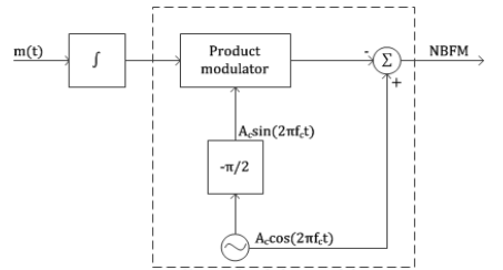
Fig 22 Narrow band phase modulator
Narrow Band FM Generator
- The frequency deviation ∆ƒ is very small in narrow-band FM wave. To produce wideband FM, we have to increase the value of ∆ƒ to a desired level.
- This is achieved by means of one or multiple frequency multipliers.
- A frequency multiplier consists of a nonlinear device and a bandpass filter. The nth order nonlinear device produces a dc component and n number of frequency modulated waves with carrier frequencies ƒc, 2ƒc, … nƒc and frequency deviations ∆ƒ, 2∆ƒ, … n∆ƒ, respectively.
- If we want an FM wave with frequency deviation of 6∆ƒ, then we may use a 6th order nonlinear device or one 2nd order and one 3rd order nonlinear devices in cascade followed by a bandpass filter centered at 6ƒc.
- Usually, we may require very high value of frequency deviation. This automatically increases the carrier frequency by the same factor which may be higher than the required carrier frequency.
- We may shift the carrier frequency to the desired level by using mixer which does not change the frequency deviation.
- The narrowband FM has some distortion due to the approximation made in deriving the expression of narrowband FM from the general expression.
- This produces some amplitude modulation in the narrowband FM which is removed by using a limiter in frequency multiplier.
Direct Method of FM Generation
- In this method, the instantaneous frequency ƒ(t) of the carrier signal c(t) is varied directly with the instantaneous value of the modulating signal n(t).
- For this, an oscillator is used in which any one of the reactive components (either C or L) of the resonant network of the oscillator is varied linearly with n(t).
- We can use a varactor diode or a varicap as a voltage variable capacitor whose capacitance solely depends on the reverse-bias voltage applied across it.
- To vary such capacitance linearly with n(t), we have to reverse-bias the diode by the fixed DC voltage and operate within a small linear portion of the capacitance-voltage characteristic curve.
- The unmodulated fixed capacitance C0 is linearly varied by n(t) such that the resultant capacitance becomes C(t) = C0 − kn(t) where the constant k is the sensitivity of the varactor diode.
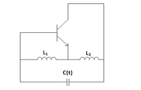
Fig 23 Hartley Oscillator
The figure shows the simplified diagram of the Hartley oscillator which is implemented as discussed above. The frequency of oscillation for such an oscillator is given by
f(t) = 1__________ --------------------(1)
2π [( 1 + L2) C(t)] 1/2
f(t) = 1__________ ------------------------------(2)
2π [( 1 + L2) C(t) (Co – km(t))] 1/2
f(t) = 1__________ -----------------------------------(3)
2π [( 1 + L2) C(t) (1 – km(t))] ½
Co
f(t) = fc(1 – km(t))] -½
Co
Where fc is the un modulated frequency of oscillation. Assuming,
k m(t)/C0 << 1
We have binomial expansion as
(1 – km(t)/Co) -1/2  1 + k m(t)/ 2C0 ------------------------------------------------(4)
f(t)  fc( 1 + km(t)/2Co)
= fc + k fc m(t) / 2Co ----------------------------------------------------(5)
f(t) fc + kf m(t) ----------------------------------------(6)
Kf = kfc/ 2Co -------------------------------------- (7)
Equation(7) is the frequency sensitivity of the modulator.
This equation is the required expression for the instantaneous frequency of an FM wave.
In this way, we can generate an FM wave by direct method. The main advantage of the direct method is that it produces sufficiently high frequency deviation, thus requiring little frequency multiplication.
But, it has poor frequency stability. A feedback scheme is used to stabilize the frequency in which the output frequency as compared with the constant frequency generated by highly stable crystal oscillator and the error signal is feedback to stabilize the frequency.
FM stereo transmitter
FM transmitter is taking the audio signal as an input and delivers FM wave to the antenna as an output to be transmitted.
The block diagram of FM transmitter is shown in the following figure.

Fig 24 FM transmitter
Working:
- The audio signal from the output of the microphone is sent to the pre-amplifier, which boosts the level of the modulating signal.
- This signal is passed to high pass filter, which acts as a pre-emphasis network to filter out the noise and improve the signal to noise ratio.
- This signal is passed to the FM modulator circuit.
- The oscillator circuit generates a high frequency carrier, which is sent to the modulator along with the modulating signal.
- Several stages of frequency multiplier are used to increase the operating frequency. Then, too the power of the signal is not enough to transmit.
Hence, a RF power amplifier is used at the end to increase the power of the modulated signal. This FM modulated output is finally passed to the antenna to be transmitted.
Requirements of a Receiver
The FM receiver receives FM wave and demodulates it by using the Frequency Discrimination method. Following are the requirements of FM receiver.
- It should be cost-effective.
- It should receive the corresponding modulated waves.
- The receiver should be able to tune and amplify the desired station.
- It should have an ability to reject the unwanted stations.
- Demodulation has to be done to all the station signals, irrespective of the carrier signal frequency.
For these requirements to be fulfilled, the tuner circuit and the mixer circuit should be very effective. The procedure of RF mixing is an interesting phenomenon.
RF Mixing
The RF mixing unit develops an Intermediate Frequency (IF) to which any received signal is converted, to process the signal effectively.
RF Mixer is an important stage in the receiver. Two signals of different frequencies are taken where one signal level affects the level of the other signal, to produce the resultant mixed output. The input signals and the resultant mixer output is illustrated in the following figures.
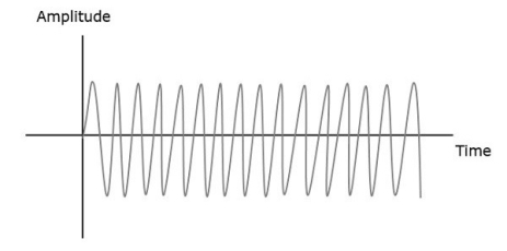
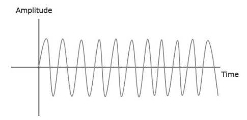
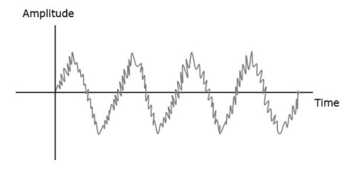
Let the first and second signal frequencies be f1 and f2. If these two signals are applied as inputs of RF mixer, then it produces an output signal, having frequencies of f1+f2 and f1−f2.
If it is observed in the frequency domain, the pattern looks like as shown the following figure.
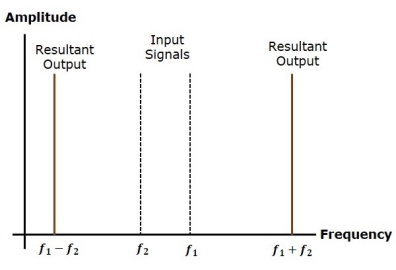
In this case, f1 is greater than f2. So, the resultant output has
Frequencies f1+f2 and f1−f2f
Similarly, if f2 is greater than f1, then the resultant output will have the frequencies f1+f2 and f1−f2
Two- way FM radio transmitter
Frequency modulation is used in a radio broadcast in the 88-108MHz VHF band. This bandwidth range is marked as FM on the band scales of radio receivers, and the devices that are able to receive such signals are called FM receivers.
The FM radio transmitter has a 200kHz wide channel. The maximum audio frequency transmitted in FM is 15 kHz as compared to 4.5 kHz in AM. This allows a much larger range of frequencies to be transferred in FM and thus the quality of FM transmission is significantly higher than of AM transmission.
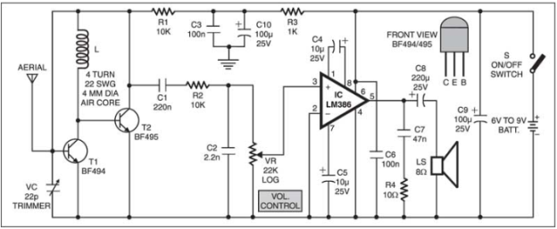
FM receiver circuit:
The simple FM receiver is as shown in the figure. The resonance frequency of this oscillator is set by trimmer VC to the frequency of the transmitting station that we wish to listen. That is, it has to be tuned between 88 and 108 MHz. The information signal is used in the transmitter to perform the modulation which is extracted on resistor R1 and fed to the audio amplifier over a 220nF coupling capacitor (C1).
Key takeaway
Amplitude Modulation | Frequency Modulation |
Bandwidth is very small | It requires much wider channel as required to AM |
The amplitude of AM varies depending on the modulation index | The amplitude of FM signal is constant independent on the depth of modulation |
Area of reception is large | Area of reception is small |
The average power in modulated wave is greater than carrier power | The average power in frequency modulated wave is same as that of un-modulated wave. |
More susceptible to noise interference and low signal to noise ratio | Noise can be easily minimized amplitude variations can be eliminated by using limiter |
Maximum value of modulation index is 1 | No restriction on modulation index. |
The satellite broadcast of television is major part of satellite communication. In 1999 the DSB-TV and video distribution were the major part of satellite communication. With technology now these DSB-TV and video distribution have become digital. They have small antenna and receiving system has very low cost. The 20-Msps QPSK signal is used in digital DBS-TV signals transmission. The 40-Mbps signal has data rate of 23-27 Mbps with remaining bits for error control and system operations.
Many errors correction and detection techniques are used in DBS-TV digital signals. The detected errors which remain after decoding of digital signal results in single word errors. The development of DBS-TV satellites with spot beam for local news broadcast has provided the higher satellite antenna gain needed for uplink from 0.5 m dishes.
Both DirectTV and Dish network offer internet access terminal with uplink capability. The satellite radio broadcast emerged in 2000 from three Sirius satellites in elliptical orbits and two XM satellites in GEO. The signals are transmitted in S band at 2.3GHz and are focused mainly in automobiles where the users are highest. To overcome signal blockage repeaters are used in cities.
Key takeaway
Both DirectTV and Dish network offer internet access terminal with uplink capability.
To overcome signal blockage repeaters are used in cities for radio transmission.
Examples
Q1) A modulating signal m(t)=10cos(2π×103t) is amplitude modulated with a carrier signal c(t)=50cos(2π×105t). Find the modulation index, the carrier power, and the power required for transmitting AM wave.
A1) Given, the equation of modulating signal as
m(t)=10cos(2π×103t)
We know the standard equation of modulating signal as
m(t)=Amcos(2πfmt)
Comparing both equations, we get
Amplitude of modulating signal as Am=10volts
And Frequency of modulating signal as fm=103Hz=1KHz
c(t)=50cos(2π×105t)
Comparing these two equations, we will get
Amplitude of carrier signal as Ac=50volts
And Frequency of carrier signal as fc=105Hz=100KHz
μ = Am/Ac
μ = 10/50 =0.2
The value of modulation index is 0.2
Carrier power, Pc
Pc=Ac2/2R
Let R=1ohm
Carrier power, Pc is 1250 watts.


Q2) The equation of amplitude wave is given by s(t)=20[1+0.8cos(2π×103t)] cos(4π×105t). Find the carrier power, the total sideband power, and the band width of AM wave.
A2) s(t)=20[1+0.8cos(2π×103t)] cos(4π×105t).
We can write above equation as
s(t)=20[1+0.8cos(2π×103t)] cos (4πx 2 x105t).

Amplitude of carrier signal as Ac=20volts
Modulation index as μ=0.8
Frequency of modulating signal as fm=103Hz=1KHz
Frequency of carrier signal as fc=2×10⁵Hz=200KHz
The formula for Carrier power, Pc
Pc=Ac2/2R
Pc = (20)2/2(1) = 200W
Total side band power is
PSB=Pcμ2/2
PSB=200× (0.8)2/2=64W
Total side band power is 64 watts.
We know the formula for bandwidth of AM wave is
BW=2fm
Substitute fm value in the above formula.
BW=2(1K) =2KHz
The bandwidth of AM wave is 2 KHz.
Q3) A carrier is phase modulated (PM) with frequency deviation of 10 kHz by a single tone frequency of 1 kHz. If the single tone frequency is increased to 2 kHz, assuming that phase deviation remains unchanged the bandwidth of the PM signal is
A3)
- In PM phase deviation,


- If the frequency
 is increased to 2 kHz and phase deviation remains unchanged.
 - The modulation index

- According to carsons rule
- Bandwidth =

Q4) Consider an FM signal  The maximum deviation of the instantaneous frequency from the carrier frequency is

Solution
- Given FM signal

- So instantaneous angle

- Instantaneous frequency
 ]
]

- We know that
- Instantaneous frequency

- Where


- Assume the given signal is of the form
- 1.
 [if carrier frequencies are same].
 - Then the given signal can be written in the form


- By applying the second condition we get [since frequencies are different in f

Q5) A device with input 𝑥(𝑡) and output 𝑦(𝑡) is characterized by: 𝑦(𝑡)=𝑥2 (𝑡). An FM signal with frequency deviation of 90 KHz and modulating signal bandwidth of 5 KHz is applied to this device. The bandwidth of the output signal is (a) 370 KHz (b) 190 KHz (c) 380 KHz (d) 95 KHz
A5) Frequency deviation Δ𝒇=𝟗𝟎𝑲𝑯𝒛
Modulating signal bandwidth = 5 KMz
When FM signal is applied to doubler frequency deviation doubles.
𝑩.𝑾 = 𝟐(Δ𝒇+𝒇𝒎) = 𝟐(𝟏𝟖𝟎+𝟓) =𝟑𝟕𝟎 𝑲𝑯z
Q6) An FM signal with a modulation index 9 is applied to a frequency tripler. The modulation index in the output signal will be (a) 0 (b) 3 (c) 9 (d) 27
A6) The frequency modulation index β is multiplied by n in n-times frequency multiplier. 𝑺𝒐, 𝜷′=𝟑×𝟗 = 27
Q7) A sinusoidal modulating waveform of amplitude 5 V and a frequency of 2 KHz is applied to FM generator, which has a frequency sensitivity of 40 Hz/volt. Calculate the frequency deviation, modulation index, and bandwidth.
A7) Given, the amplitude of modulating signal, Am=5V
Frequency of modulating signal, fm=2KHz
Frequency sensitivity, kf=40Hz/volt
We know the formula for Frequency deviation as
Δf=kfAm
Δf=40×5=200Hz
β=Δf/fm
β=200/(2×1000) = 0.1
The formula for Bandwidth of Narrow Band FM is the same as that of AM wave.
BW=2fm
BW=2×2K=4KHz
Q8) An FM wave is given by s(t)=20cos(8π×106t+9sin(2π×103t)). Calculate the frequency deviation, bandwidth, and power of FM wave.
A8) s(t)=20cos(8π×106t+9sin(2π×103t))
We know the standard equation of an FM wave as
s(t)=Accos(2πfct+βsin(2πfmt))
Amplitude of the carrier signal, Ac=20V
Frequency of the carrier signal, fc=4×10⁶Hz=4MHz
Frequency of the message signal, fm=1×10³Hz=1KHz
Modulation index, β=9
β=Δf/fm
Δf=9×1K=9KHz
The formula for Bandwidth of Wide Band FM wave is
BW=2(β+1)fm
BW=2(9+1)1K=20KHz
The bandwidth of Wide Band FM wave is 20KHz
Pc=Ac2/2R
P= (20)2/2(1) =200W
Therefore, the power of FM wave is 200watts.
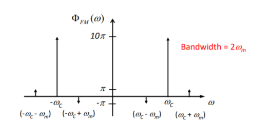
Q9) The message signal input to a modulator is m(t) = 4cos(2104 t) and the carrier is 10cos(108 t). If frequency modulation is performed with kf = 1000, verify that the modulated signal meets the criteria of being narrowband FM. Also, obtain an expression for its spectrum and sketch this spectrum.
A9) First we calculate the modulation index 


The corresponding expression for the spectrum becomes

Where  and
and 
Q10) For commercial FM radio, the audio message signal has a spectral range of 30 Hz to 15 kHz, and the FCC allows a frequency deviation of 75 kHz. Estimate the transmission bandwidth for commercial FM using Carson’s Rule.
A10) We know
β=Δf/fm = 75/15 =5
Using Carson's rule gives
BFM = 2(β+1)fm = 2(5+1)x15,000= 180kHz
The allowed bandwidth for commercial FM is 200 kHz.
References:
[1] John G.Proakis, M. Salehi, Communication Systems Engineering, 2nd ed. New Delhi, India. PHI Learning Private Limited, 2009.
[2] R.P Singh and S.D Sapre, Communication Systems Analog & Digital, 2nd ed. New Delhi, India. Tata McGraw Hill Education Private Limited, 2009.