Unit - 5
Two Port Network and Network Functions

Fig. Port networks
The above network is a 2-port network with input port having voltage V1 and current I1 and output port with voltage V2 and current I2.

Fig. port network
The above network is a 1 port network with one port having voltage V1 and current I1.
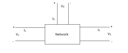
Fig. port network
z-parameter  open circuit impedance
y-parameter  short circuit admittance
h-parameter  hybrid parameter
g-parameter  inverse hybrid parameter
ABCD-parameter  transmission parameter
A’B’C’D’ parameter  inverse transmission
s-parameter  scattering
used for very high frequency application
A) One port Network:
The one port network can be represented as shown below. it has only one port i.e., input port or only output port.

Fig. one port networks
1) Driving point impedance at input port
Z11(S) = V1(S) / I1(S)
2) Driving point impedance at output port
Z22(S) = V2(S) / I2(S)
3) Driving point admittance at input port
Y11(S) = I2(S) / V2(S)
4) Driving point admittance at output port
Y22(S) = I2(S) / V2(S)
After studying above equations, it can be clearly that
Z11(S) = 1 / Y11(S) And Z22(S)=1/Y22(S)
B) Two Port Network:
The network as the name says has two one input and other output port.

Fig Two port network
1)Transfer Function impedance Z11(S) = V2(S) / I1(S)
2) Transfer admittance function Y12(S) = I2(S) / V1(S)
3) Current ratio transfer function Y12(S) = I2(S) / I1(S)
4)Voltage ration transfer function G12(S) / V2(S) / V1(S)
Key takeaway
Driving point impedance at input port
Z11(S) = V1(S) / I1(S)
Transfer Function impedance for two port networks
Z11(S) = V2(S) / I1(S)
Transfer admittance function Y12(S) = I2(S) / V1(S)
Current ratio transfer function Y12(S) = I2(S) / I1(S)
Voltage ration transfer function G12(S) / V2(S) / V1(S)
Q1) For the network shown below 1) show that with port 2) open the driving point input impedance 1π) b) find the voltage, ratio transfer function 1/2 for the two-port network.
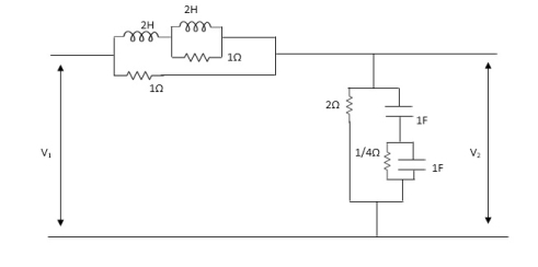
Solution: From above network we take L.T
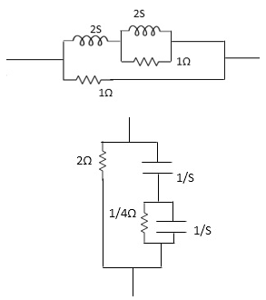
Fig. Laplace Transform for above circuit
Reducing 4 we gel,
Z1= (25+25*1 / 25+1) *1
25+25*1 / 25+1*1
Z1=4S2+45/452+65+1
Z2=(1/4S/1/4+1/5+1/5) *2=1/45/1/4+1/3+1/5+2
=2(5+5+4) / 5+5+4+25(5+4) = 2(25+4)/252+10S+4
Z2=25+4/252+10+4
Applying KVL, in the circuit
V1=I1Z1+I, Z2 -----------1
V2= I1Z2 ...............2
.: V1=I1Z1+V
V1 / I1= (Z1+Z2) (from----1)
Dividing equation 2 by 1
G12=Z 2 / Z1+Z2
calculating z11 we have,
Z11=Z1+Z2
Z11 = 4S2+4S / 4S2+6S+1 * 2S+4/S2+SS+2
=(4S2+4S) (S2+SS+2) +(2S+4) (4S2+6S+1) / (4S2+6S+1) (S2+SS+2)
Z11=4S4+20S3+8S2+4S3+20S2+8S+8S3+12S2+25+16S2+4 /(4S2+6S+1) (S2+SS+2)
= (4S4+32S3+5652+345+4 / (4S2+6S+1) (S2+SS+2)
G12= Z2 / Z1+Z2
= (2S+4) / (S2+SS+2) / (4S+32S3+56S2+34S+4) / (4S2+6S+1) (S2+SS+)
G12= (2S+4) (4S2+6S+1) / 4S4+32S3+56S2+34S+4
Poles and Zeros
Let us consider the following transfer function

a, b- coefficient with are real and positive
Features of poles and zero of network function.
a) The network function is described by poles and zeros.
b) The zeros of the network exist for the complex frequencies where N(s)=0
c) The poles of the network exist for the complex frequencies where N(s)=o
d)The number of poles is equal to number of zeros considering types poles and zeros which at infinity.
e) when n>m, poles at infinity has degree(n-m)
f) When m>n, zeros at infinity with degree (m-n)
g) The time variation response of the network is determined through the poles.
h) The magnitude of response is determined by poles and zeros of the network function.
i) If q(s) =0, is the characteristics equation of N(S).
J) Capacitor is represented as (ʊ)=1/cs so, for
S = 0, It behaves open circuits
S= behaves as short circuit
k) For inductor z(s) = Ls
so, for s= 0 It behaves short circuit
s = It behaves as given circuits
Key takeaway
The zeros of the network exist for the complex frequencies where N(s)=0
The poles of the network exist for the complex frequencies where N(s)=o
Que) For the network shown, find driving point input impedance. plot the pole zero pattern for each as well.

Fig (i) Circuit Diagram Fig (ii) Circuit Diagram
Solution From Fig 7(1) taking L.T we have
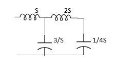
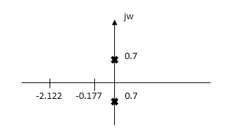
Fig. Laplace for Fig (i) with roots
Z11= 1+ 1 /S/3+1/25+1/1/4S
=1+ 1/ 5/3+1/6S
=1+ 18S/6S2+3
Z11=6S2+3+18S/ 6S2+3 =2S2+6S+2/2S2+1
Zeros of equations are taking lt. of circuit b)
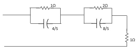
Fig. Laplace for Fig (ii)
Z11= 1*4/5
=1+4/5+2.8/3/2+8/5+1
=4/5+4 + 16/ 25+8+1
= 4/5+4+8/5+4+1
=s+12+4/ (5+4)
Z11= S+16/(S+4)
For zeros of system
s+16=0
s=-16
for poles of system
s+4=0
s=-4
Relationship of Two-Part Variables
Condition for Reciprocity and Symmetry
Sr No. | Parameter | Reciprocity | Symmetry |
1. | Z Parameter | Z12 = Z21 | Z11= Z22 |
2. | Y Parameter | Y12 = Y21 | Y12 = Y21 |
3. | h Parameter | h12 = h21 | Δ = 1 |
4. | ABCD Parameter | AD-BC = 1 | A = D |
5. | Inverse h Parameter | g12 = g21 | Δ = 1 |
6. | Inverse Transmission | A1D1 – B1 C1= 1 | A1 = D1 |
Relation between Two- Port Parameters: -
Δ = X11 X22 – X12 X21, ΔT = AD – BC
| [z] | [y] | [h] | [T] |
[z] | Z11 Z12 | y22 – y12
| Δh – h12
| A – ΔT
|
Z21 Z22 | y21 – y11
| -h21 h
| 1 D
| |
|
|
|
|
|
[y] | Z22 -Z12
| y11 y12 | 1 -h12
| D – ΔT
|
-Z21 Z11
| y21 y22 | h21 Δn
| -1 A
| |
|
|
|
|
|
[h] | Δz Z12
| 1 -y12
| h11 h12 | B ΔT
|
-Z21 -1
| y21 Δy
| H21 h22 | -1 C
| |
[T] | Z21 ΔZ
| -y22 -1
| -Δh -h11
| A B |
1 Z22
| -Δy -y11
| -h22 -1
| C D |
Open circuit impedance parameters
Z-parameter:
v1 = Z11I1 + Z12I2
v2 = Z11I1 + Z22I2
 =
= 
Z11 =  I2=0
I2=0
Z12 =  I1=0
I1=0
Z21 =  I2=0
I2=0
Z22 =  I1=0
I1=0
 I1 and I2 are excitations at ports 1 & 2 respectively.
 V1 and V2 are the responses at ports 1 and 2 respectively.
Equivalent circuit:
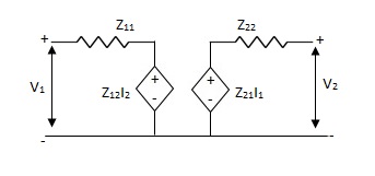
Fig Equivalent z-parameter circuit
Symmetry:
 I2=0 =
 I1 = 0
Z11 = Z22
Reciprocal two-port N/W:
 I2=0=
I2=0=  I1=0
I1=0
Z12 = Z21
I1& I2 should be independent
Que 1.
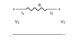
Find Z-parameter
Solution: I1 = -I2
Current dependent so Z-parameter doesn’t exist
Que 2.
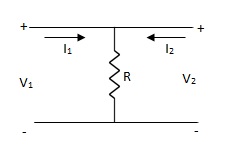
Find z-parameter
Solution: V1 =R (I1 + I2)
V2 = R (I1 + I2)
Z11 = Z12 = Z21 = Z22 = R
Que 3.
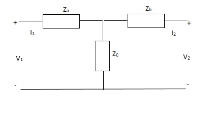
Solution: V1 = I1Za + I1Zc + I2Zc
= (Za + Zc) I1 + ZcI2
V2 = I2Zb + I2Zc + I1Zc
= (Zb + Zc) I1 + ZcI1
Z11 = (Za + Zc)
Z12 = Zc = Z21
Z22 = (Zb + Zc)
Que 4.
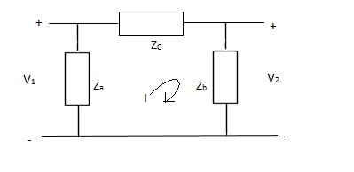
Solution: V1 = Za (I1 - I)
(I - I1) Za+ IZc+ Zb (I + I2) = 0
I (Za + Zb + Zc) – I1Za + I2Zb = 0
I = 
V1 = ZaI1 - Za
=  I1 + I2
V2 = Zb (I2 + I)
= ZbI2 + Zb
=  I2 + I2
Z11 = 
Z12 = Z21 = 
Z22 = 
Can be solved by Y-A conversion
Que 1.
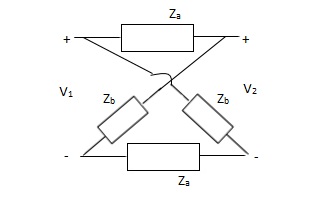
Solution:
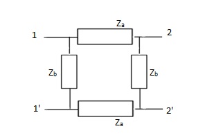
Z11 =  I2=0
I2=0
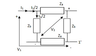
V1 -  (Za + Zb) = 0
 = Z11 =
Z21 =  I2=0
I2=0
V2 -  Zb +
Zb + Za = 0
 =
= 
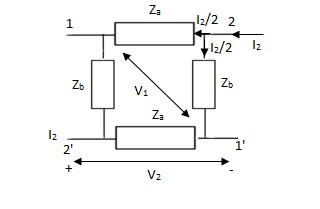
Z12 = 
Z22 = 
Que 2.
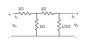
Find Z21?
Solution: Z21 =  I2=0
I2=0
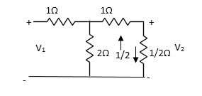
I1/2 = 
=  I1
I1
V2 =  I1/2
I1/2
=  ×
×  I1
I1
=  I1
I1
Z21 =  I2 = 0 =
  I1 Ω
I1 Ω
Short circuit Admittance parameters
Y-parameter: -
I1 = Y11V1 + Y12V2
I2 = Y21V1 + Y22V2

Y11 =  V2=0
V2=0
Y12 =  V1=0
V1=0
Y21 =  V2=0
V2=0
Y22 =  V1=0
V1=0
V1& V2 should be independent
Equivalent circuit: -
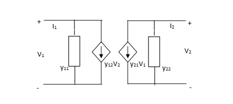
Fig. Equivalent Y-parameter circuit
Symmetrical two-port N/W: -
 I2 = 0 =
  I1=0
I1=0
Y12 = Y22
Reciprocal two-port N/W: -
 I1=0 =
 I2 = 0
Y12 = Y21
Que 1. Find overall Y-parameter?
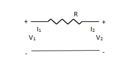

Solution: V1 – I1R – V2 = 0
V1 – V2 = I1R
I1 =  V1 -
V1 -  V2
V2
V2 = I2R + V1
I2 = -  V1 +
V1 +  V2
V2
Y11 = 
Y12 = Y21 = 
Y22 = 
Que 2. Find overall Y-parameter
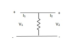
Solution: Y-parameter does not exist as V1 = V2
Que 3. Find overall Y-parameter?
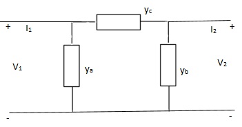
Solution: I1 = V1Ya + (V1 – V2) Yc
I1 = (Ya + Yc) V1 - YcV2
I2 = V2Yb + (V2 – V1) Yc
I1 = (Yb + Yc) V2 - YcV1
Y11 = Yb + Yc
Y12 = Y21 = - Yc
Y22 = Yb + Yc
Que 4. Find overall Y-parameter?
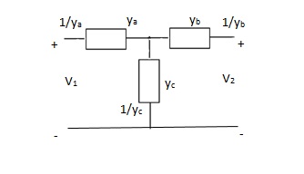
Solution:
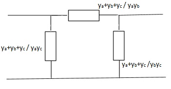
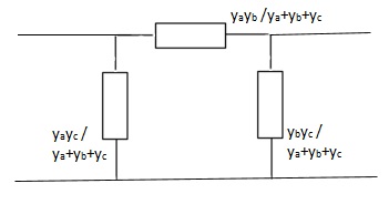

Transmission parameter [ABCD]
V1 = AV2 - BI2
I1 = CV2 - DI2

A =  I2=0
I2=0
B =  V2=0
V2=0
C =  -I2=0
-I2=0
D =  V2=0
V2=0
Symmetrical two-port N/W: -
 I2 = 0 =
  I1=0
I1=0
A = D
Reciprocal two-port N/W: -
 I1=0 =
 I2 = 0
AD – BC = 1
Que 1. Find all the Transmission parameters?
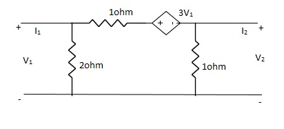
Solution:
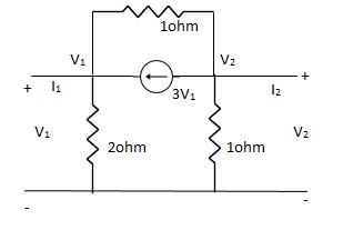
-3V1 – I1 +  +
+  = 0
= 0
 +
+  = I1
= I1
 V1 – V2 = I1
 V1 = V2 + I1
V1= V2-
V2-  I1----------------(1)
I2 = 3V1 + V2 + V2 – V1
I2 = 2V1 + 2V2
2V1 = I2 - 2V2
2V1 = - 2V2 + I2
V1 = -V2 +  I2 ----------------(2)
A = -1
B = 
From (1) & (2)
-V2 +  I2 =
I2 =  I1 -
I1 -  V2
V2
 V2 - V2 +
  I2 =
I2 =  I1
I1
 I1 =
I1 =  V2 + V2 -
  I2
I2
I1 =  V2 -
V2 -  I2
I2
C = 
D = 
Que 2. Find all the Transmission parameters?
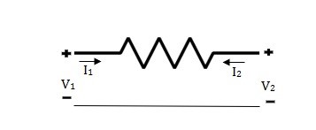
Solution: V1 = RI1 + V2 ----------------(1)
I2R = V2 – V1
I2 =  V2 -
V2 -  V1
V1
I2R = V2 – V1
V1 = I2R - V2 --------------------(2)
A = 1
B = R
From (2) in (1)
V2 - I2R = V2 + RI1
I2 = -I1
C = 0
D = 1
Que 3. Find all the Transmission parameters?
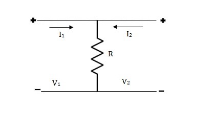
Solution: V1 = R (I1 + I2)
V2 = R (I1 + I2)
V1 = V2 + 0I2
A = 1
B = 0
V2 = RI1 + RI2
RI1= V2 - RI2
I1 =  V2 – I2
C =  , D = 1
Hybrid Parameter
H-parameter: -
V1 = h11I1 + h12V2
I2 = h21I1 + h22V2
Equivalent circuit for H-parameter:
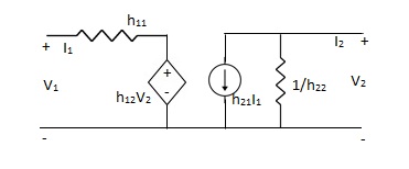
Fig 12 Equivalent circuit for H-parameter
h11 =  V2=0
V2=0
h12 =  I1=0
I1=0
h21 =  V2=0
V2=0
h22 =  I1=0
I1=0
Symmetrical two-port N/W: -
 I2 = 0 =
  I1=0
I1=0
∆h = 0
Reciprocal two-port N/W: -
 I1=0 =
 I2 = 0
h12 = h21
Que 4. Find all h-parameter?
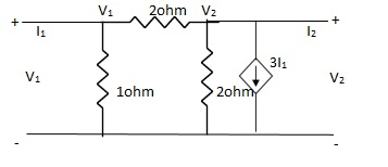
Solution: +
+  = I1
= I1
 V1 -
V1 -  = I1
= I1
 V1 =
V1 =  + I1
+ I1
V1 = +
+  I1
I1
-  + 3I1 = I2
3I1 + V2 = I2
= I2
From (1)
I2 = 3I1 + V2 –  [
[ I1 +
I1 +  V2]
V2]
I2 =  I1 +
I1 +  V2
V2
h11 = 
h12 = 
h21 = 
h22 = 
Series connection
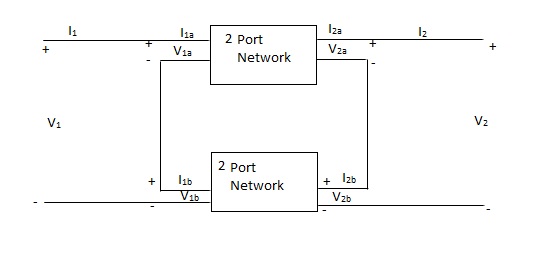
V1 = V1a +V1b
I1 = I1a = I1b
V2 = V2a +V2b
I2 = I2a = I2b
 =
= 
 =
= 
 =
= 
Parallel connection
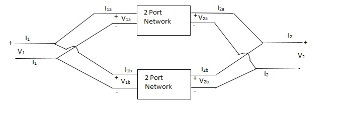
V1 = V1a = V1b
 =
= 
 =
= 
 =
= 
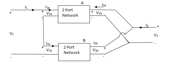
Series parallel connection
I1 = I1a = I1b
V1 = V1a +V1b
If two 2-ports are connected in series parallel then overall h-parameter is sum of individual h-parameter
 =
= 
Parallel series connection
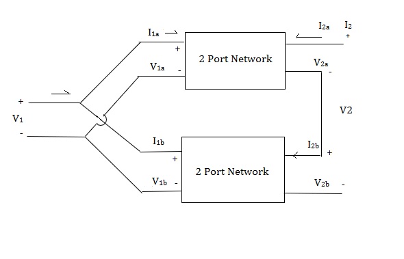
 =
= 
Cascade connection

V1 = V1a, V2a = V1b, V2 = V2b
I1 = I1a, I2a = -I1b, I2 = I2b
Transmission parameter for N/W (A)

Transmission parameter for N/W (B)

Overall transmission parameter

Que 1.
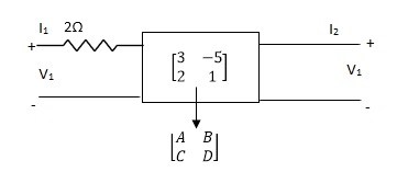
Find out overall transmission parameter?
Solution:
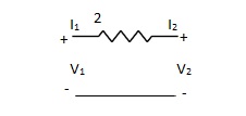


Que 2.
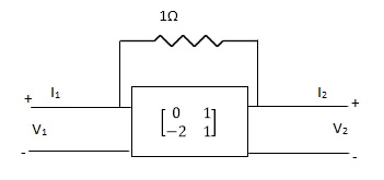
Find overall Y-parameter?
Solution:


References:
Education, 2013.
4. C. K. Alexander and M. N. O. Sadiku, “Electric Circuits”, McGraw Hill Education, 2004.
5. K. V. V. Murthy and M. S. Kamath, “Basic Circuit Analysis”, Jaico Publishers, 1999.


