Unit - 5
Formulation of Field Equations
Maxwell’s equation can be combined into a wave equation by making use of the vector identity
 (1)
(1)
Let us apply the identity above to the Maxwell’s electric field curl equation
 (2)
(2)
In a region of space free of charges, ∇~ ·E~ = 0. Assuming that we are only interested in well-behaved analytic functions (i.e., those for which we can reverse the order of differentiations with impunity), we can transform the magnetic field term in Equation 2 from the curl of a time derivative to the time derivative of a curl.


If we assume that the region of interest is also current-free, we can replace D~ with  E~ to obtain

Above equation is the wave equation for electric field. Similarly, the wave equation for magnetic field is given below

Key takeaway

Above equation is the wave equation for electric field. Similarly, the wave equation for magnetic field is given below

Waveguide is a linear structure that conveys EM waves between its end points. At frequencies more the 3GHz losses in the transmission line and cable become significant due to losses that occur in the dielectric needed to support the conductor and within the conductor itself. In general, a waveguide consists of hollow metallic tube of a rectangular or circular shape used to guide an EM wave by successive reflections from the inner walls of tube.
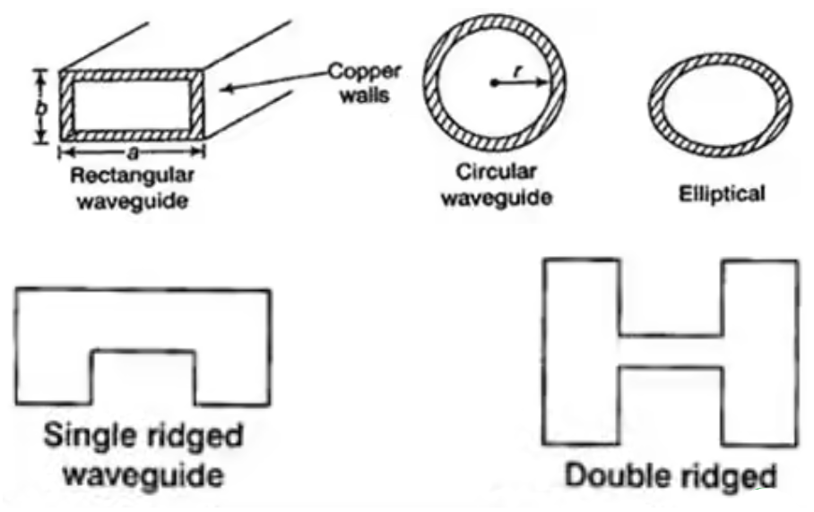
Fig 1 Types of waveguides
In the waveguide no traverse electromagnetic mode can exist but TE and TM wave can exist. The dominant mode in particular guide is the mode having the lowest cut-off frequency.
For a parallel-plate waveguide, the plates are infinite in the y-extent; we need to study the propagation in the z-direction. The following assumptions are made in the wave equation.


These two conditions define the TE modes and the wave equation.


At x = 0, Ey = 0 which leads to A + B = 0. Therefore, A = -B = Eo/2j, where Eo is an arbitrary constant
At x = a, Ey (x, z) = 0. Let a be the distance separating the two PEC plates
Moreover, from the differential equation
where m = 1, 2, 3, ... Since propagation is to take place in the z direction, for the wave to propagate, we must have z 2 > 0, or
This leads to the following guidance condition which will ensure wave propagation The cutoff frequency fc is defined to be at the onset of propagation
The cutoff frequency is the frequency below which the mode associated with the index m will not propagate in the waveguide. Different modes will have different cutoff frequencies. The cutoff frequency of a mode is associated with the cutoff wavelength c
Each mode is referred to as the TEm mode. It is obvious that there is no TE0 mode and the first TE mode is the TE1 mode.
Magnetic Field


As can be seen, there is no Hy component, therefore, the TE solution has Ey, Hx and Hz only.

From the dispersion relation, it can be shown that the propagation vector components satisfy the relations

where is the angle of incidence of the propagation vector with the normal to the conductor plates. The phase and group velocities are given by
 and
and 
The effective guide impedance is given by:

Transverse Magnetic Mode
The magnetic field also satisfies the wave equation


For TM modes, we assume

Assume  only
only
These two conditions define the TM modes


From 


At x=0, Ez = 0 which leads to A = B = Ho/2 where Ho is an arbitrary constant. This leads to


At x =a, Ez = 0 which leads to
 where
where 
This defines the TM modes which have only Hy, Ex and Ez components. The effective guide impedance is given b

For TE Mode


For TM Mode


Key takeaway
The dispersion relation, guidance condition and cutoff equations for a parallel-plate waveguide are the same for te and tm modes.
Rectangular waveguide is situated in the rectangular coordinate system with its breadth along x-direction, width along y-direction and z-indicates direction of propagation. Vector Helmholtz equation is

For TE wave (


 Propagation constant
 Phase constant
= attenuation constant

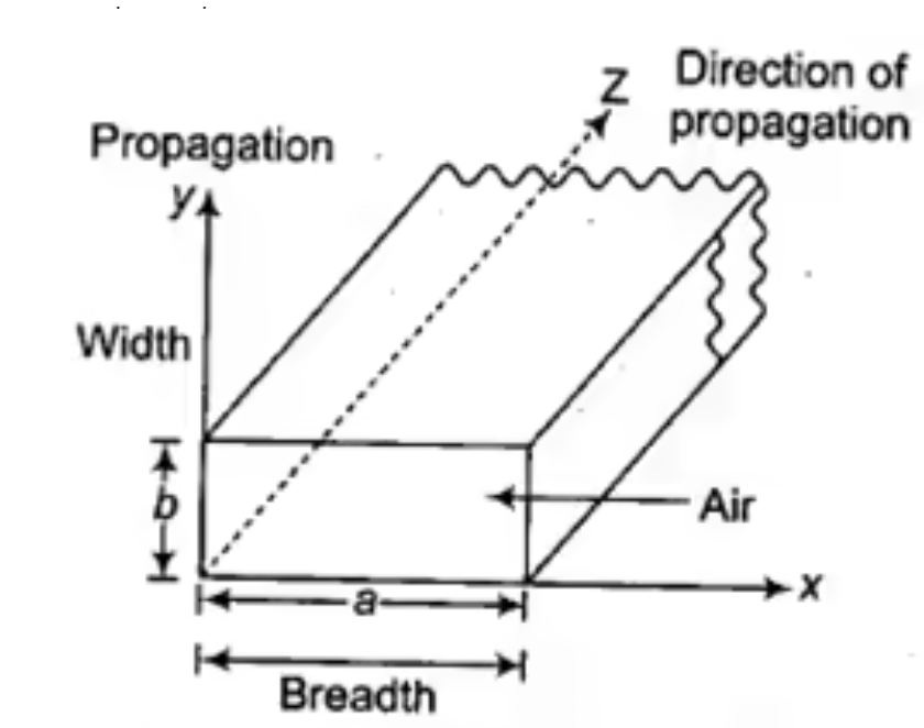
Fig 2 Rectangular Waveguide


Solving above equations we find  and
and 
Also applying Maxwell equations, we can find 


Key takeaway
For TEM wave Ez=0 and Hz=0 putting these values in above equation all field components along x and y directions. Ex, Ey, Hx, Hy vanishes and hence TEM wave cannot exist inside waveguide.
The EM wave inside rectangular waveguide has an infinite number of patterns called as modes. Generally, two types of mode (TE and TM) are present in the waveguide. These modes are denoted as TEmn and TMmn.
m=half wave variation along wider dimension a
n= Half wave variation along narrow dimension b
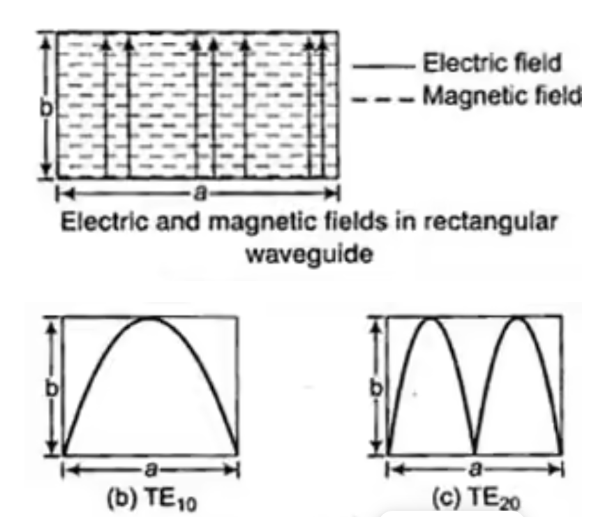
Fig 3 TE10 and TE20 mode in rectangular waveguide
TM modes of propagation in a Rectangular waveguide
For TM mode  the z component of electric field E must exist in order to have energy transmission in the guide.
The  mode field equations are


Some of the TM mode characteristic equations are same as that of TE mode but some are different and they are given as


TE modes of propagation in a Rectangular waveguide
TEmn modes in rectangular cavity are characterized by Ez = 0 which means z component of magnetic field Hz must be existing in order to have energy transmission in guide. TEmn field equation in rectangular wave guide are


Propagation Constant:
The propagation of the wave in the guide is assumed in positive z- direction. Propagation constant  in waveguide differs from intrinsic propagation constant of dielectric.

 is cut-off wave number
For lossless dielectric 

Cut-off Wave Number
The Cut-off Wave Number h is defined by

for  mode
mode
There are three cases for the propagation constant  in waveguide.
Case 1:
If  , then
  Hence there will be no wave propagation (evanescence) in the guide.
Thus at a given operating frequency f, only those mode having f>fc will propagate, and
Modes with  will lead to imaginary β (or real ).
Such modes are called evanescent modes. The cut-off frequency is 
Case 2:
If 

Case 3:
If 

So, wave cannot propagate through waveguide as  is a real quantity

For free space/loss less dielectric 

The phase velocity in the positive z-direction for the 

 is the phase velocity in vacuum.
The characteristic wave impedance of  mode in the guide


Key takeaway


 mode:
mode: 
 mode:
mode: 
 mode,
mode,

Similarly for TM mode also, different modes represent different cut-off wavelength.
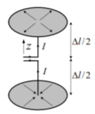
The infinitesimal dipole is a straight-line segment of length l, which is much smaller than the wavelength of the excited wave, i.e., l (Δl < / 50), and which supports constant current distribution I along its length. The assumed positive direction of the current I determines the orientation of the line segment: ˆ I = li. The infinitesimal dipole is mathematically described by a current element

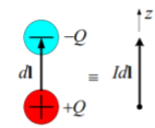
A current element is best illustrated by a very short (compared to 𝜆) piece of infinitesimally thin wire with current I. For simplicity, the current is assumed to have constant magnitude along dl. The ideal current element is practically unrealizable, but a very good approximation of it is the short top-hat antenna. To realize a uniform current distribution along the wire, capacitive plates are used to provide enough charge storage at the end of the wire, so that the current is not zero there.
The magnetic vector potential A due to a linear source is:

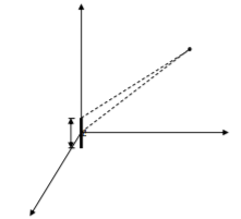
Where 𝛽is the wavenumber

and it is related to the wavelength and as:

Since the dipole is very small, R r both in the exponent term and in the denominator. Therefore,

In above equation gives the field due to an electric current element (infinitesimal dipole) expressed via A. This is an important result because the field radiated by any complex antenna in a linear medium can be represented as a superposition of the fields due to the current elements on the antenna surface.
We represent A with its spherical components. In antenna theory, the preferred coordinate system is the spherical one. This is mostly because the far field radiation is of interest. The field is analyzed so very far from the source, that it is assumed to propagate only radially away from the source. The transformation from rectangular to spherical coordinates is given by

Applying transformation to Az produces


Field Vector due to current element radiation

The curl operator is expressed in spherical coordinates to obtain


Explicitly, in spherical coordinates we find:
 and
and 
Equations above show that the EM field generated by the current element is rather complicated unlike the VP A. The use of the VP instead of the field vectors is usually advantageous in antenna studies.
2- The field vectors contain terms, which depend on the distance from the source as (1/r), (1/r 2) and (1/r 3); the higher-order terms can be neglected at large distances from the dipole.
3- The longitudinal 𝒓̂-components of the field vectors decrease fast as the field propagates away from the source (as 1/r 2 and 1/r 3 only): they are neglected in the far zone.
4- The non-zero transverse field components, 𝐸𝜃 and 𝐻𝜑, are orthogonal to each other, and they have terms, which depend on the distance as 1/r. These terms differ by a factor of 𝜂. They represent the so-called far field.
Key takeaway
1) Az does not depend on (due to the cylindrical symmetry of the dipole)
2) the dependence on r, which is 𝑒 −𝑗𝛽𝑟 ⁄ 𝑟, is separable from the dependence on .
The dipole antenna is cut and bent for effective radiation. The length of the total wire, which is being used as a dipole, equals half of the wavelength (i.e., l = λ/2). Such an antenna is called as half-wave dipole antenna. This is the most widely used antenna because of its advantages. It is also known as Hertz antenna. The range of frequency in which half-wave dipole operates is around 3KHz to 300GHz. This is mostly used in radio receivers.
It is a normal dipole antenna, where the frequency of its operation is half of its wavelength. Hence, it is called as half-wave dipole antenna.
The edge of the dipole has maximum voltage. This voltage is alternating (AC) in nature. At the positive peak of the voltage, the electrons tend to move in one direction and at the negative peak, the electrons move in the other direction. This can be explained by the figures given below.

Fig 4 Half wave Dipole
The cumulative effect of this produces a varying field effect which gets radiated in the same pattern produced on it. Hence, the output would be an effective radiation following the cycles of the output voltage pattern. Thus, a half-wave dipole radiates effectively.
The radiation pattern of this half-wave dipole is Omni-directional in the H-plane. It is desirable for many applications such as mobile communications, radio receivers etc.
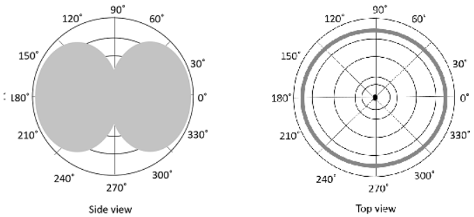
Fig 5 Radiation Pattern of Half-wave Dipole
The above figure indicates the radiation pattern of a half wave dipole in both H-plane and V-plane.
The radius of the dipole does not affect its input impedance in this half wave dipole, because the length of this dipole is half wave and it is the first resonant length. An antenna works effectively at its resonant frequency, which occurs at its resonant length.
Key takeaway
The half wave dipole antenna has the following advantages
It is the most commonly used type of antenna for TV reception over the last few decades. It is the most popular and easy-to-use type of antenna with better performance, which is famous for its high gain and directivity. The frequency range in which the Yagi-Uda antennas operate is around 30 MHz to 3GHz which belong to the VHF and UHF bands.
A Yagi-Uda antenna was seen on top of almost every house during the past decades. The parasitic elements and the dipole together form this Yagi-Uda antenna. The figure shows a Yagi-Uda antenna. It is seen that there are many directors placed to increase the directivity of the antenna. The feeder is the folded dipole. The reflector is the lengthy element, which is at the end of the structure.
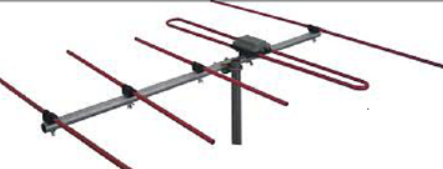
Fig 6 Yagi Uda Antenna
The center rod like structure on which the elements are mounted is called as boom. The element to which a thick black head is connected is the driven element to which the transmission line is connected internally, through that black stud. The single element present at the back of the driven element is the reflector, which reflects all the energy towards the direction of the radiation pattern. The other elements, before the driven element, are the directors, which direct the beam towards the desired angle.
The directional pattern of the Yagi-Uda antenna is highly directive as shown in the figure given below.
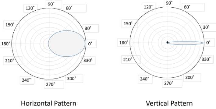
Fig 7 Yagi Uda Antenna
The minor lobes are suppressed and the directivity of the major lobe is increased by the addition of directors to the antenna.
Key takeaway
The following are the advantages of Yagi-Uda antennas −
Parabolic Reflectors are Microwave antennas. The frequency range used for the application of Parabolic reflector antennas is above 1MHz. These antennas are widely used for radio and wireless applications. The standard definition of a parabola is - Locus of a point, which moves in such a way that its distance from the fixed point (called focus) plus its distance from a straight line (called directrix) is constant.
The following figure shows the geometry of parabolic reflector. The point F is the focus (feed is given) and V is the vertex. The line joining F and V is the axis of symmetry. PQ are the reflected rays where L represents the line directrix on which the reflected points lie (to say that they are being collinear). Hence, as per the above definition, the distance between F and L lie constant with respect to the waves being focussed.
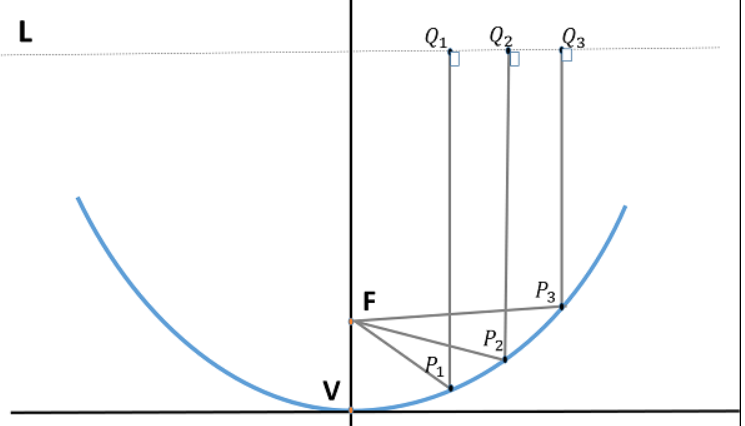
Fig 8 Parabolic Antenna
The reflected wave forms a collimated wave front, out of the parabolic shape. The ratio of focal length to aperture size (i.e., f/D) known as “f over D ratio” is an important parameter of parabolic reflector. Its value varies from 0.25 to 0.50.
The law of reflection states that the angle of incidence and the angle of reflection are equal. This law when used along with a parabola, helps the beam focus. The shape of the
parabola when used for the purpose of reflection of waves, exhibits some properties of the parabola, which are helpful for building an antenna, using the waves reflected.
If a Parabolic Reflector antenna is used for transmitting a signal, the signal from the feed, comes out of a dipole or a horn antenna, to focus the wave on to the parabola. It means that, the waves come out of the focal point and strike the Paraboloidal reflector.
The gain of the paraboloid is a function of aperture ratio (D/λ). The Effective Radiated Power (ERP) of an antenna is the multiplication of the input power fed to the antenna and its power gain. Usually, a wave guide horn antenna is used as a feed radiator for the paraboloid reflector antenna. Along with this technique, we have another type of feed given to the paraboloid reflector antenna, called as Cassegrain feed.
Cassegrain is another type of feed given to the reflector antenna. In this type, the feed is located at the vertex of the paraboloid, unlike in the parabolic reflector. A convex shaped reflector, which acts as a hyperboloid is placed opposite to the feed of the antenna
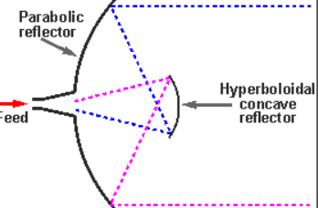
Fig 9 Cassegrain Feed
It is also known as secondary hyperboloid reflector or sub-reflector. It is placed such that it’s one of the foci coincides with the focus of the paraboloid. Thus, the wave gets reflected twice.
Key takeaway
Parabolic reflector antenna
References: