Unit - 2
Constant magnetic field
1. It has a continuously current producing but strong pulse of the magnetic field.
2. Around a permanent magnet or a wire carrying a steady electric current in one direction, the magnetic field is stationary and referred to as a magneto static field. At any given point its magnitude and direction remain the same.
3. Around an alternating current or a fluctuating direct current, the magnetic field is continuously changing its magnitude and direction.
4. A uniform magnetic field is represented by equally spaced parallel straight lines., the magnetic field is stationary and referred to as a magneto static field..
5. The lines of flux are continuous, forming closed loops.
6. The SI unit for magnetic flux is the weber.
Key Takeaways:
1. The magnetic field is stationary and referred to as a magneto static field.
2. The magnetic field is stationary and referred to as a magneto static field.
1. A pulsed field magnet is a strong electromagnet which is powered by a brief pulse of electric current through its windings rather than a continuous current, producing a brief but strong pulse of magnetic field.
2. Pulsating magnetic field created by this AC current will also be of sinusoidal shape.
3. The magnetic field here can be called as 'pulsating' because the magnitude of the magnetic field i.e. flux density changes its magnitude with time at frequency of supply voltage
Key Takeaways:
1. Flux density changes its magnitude with time at frequency of supply voltage
2. As Pulsating magnetic field created by this AC current will also be of sinusoidal wave.
1. In constant magnetic field, the pulsating magnetic field and the alternating current in windings are with spatial displacement.
2. The magnetic field produced by a single winding, it has fixed current and alternating current pulsating field is produced by spatially displaced winding. The winnings are shifted by 90 degrees.
Key Takeaways:
1. The winnings are shifted by 90 degrees.
2. The magnetic field has fixed current and alternating current.
1. The rotating magnetic field is the key principle in the operation of induction machines.
2. The induction motor consists of a stator and rotor.
3. In the stator a group of fixed windings are so arranged that a two phase current, for example, produces a magnetic field which rotates at an angular velocity determined by the frequency of the alternating current.
4. The rotor or armature consists of coils wound in slots, which are short circuited and in which the changing flux generated by the field poles induce a current.
5. The flux generated by the armature current reacts upon the field poles and the armature is set in rotation in a definite direction.
Key takeaways:
1. A magnetic field which rotates at an angular velocity determined by the frequency of the alternating current.
2. The flux generated by the armature current reacts upon the field poles
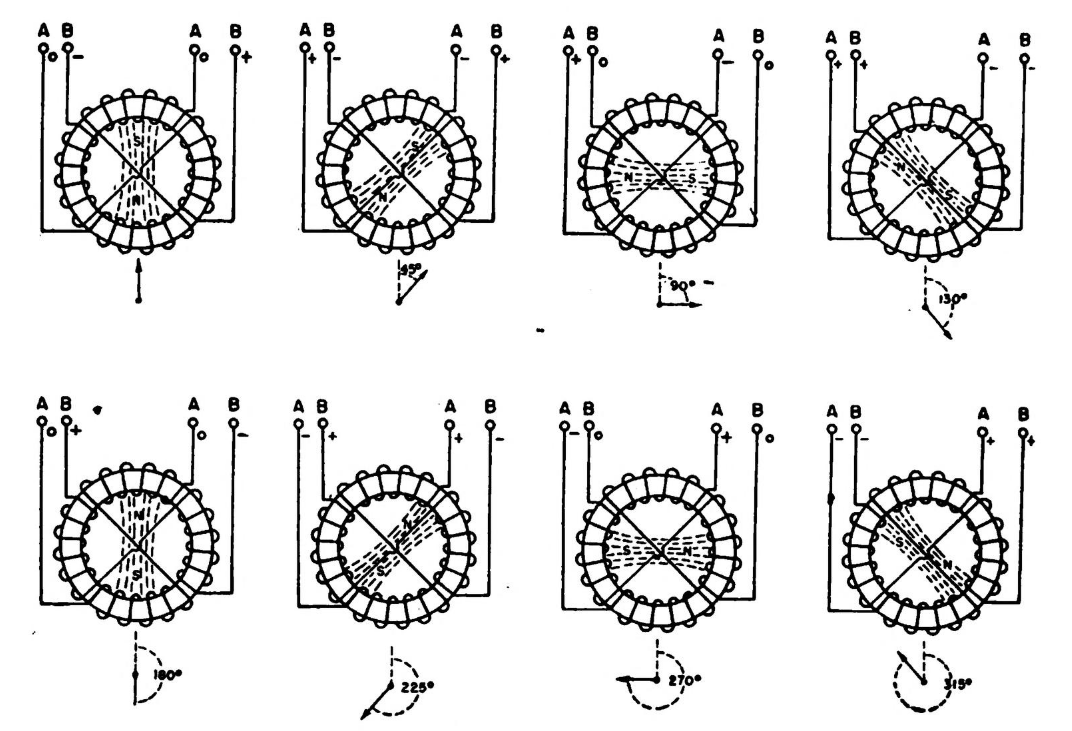
Fig 1: Magnetic field produced in single winding
1. In fig 1 all w/p windings per pole and phase are distributed over q slots.
2. Any of the w/pq conductors per slot show a spatial displacement of The resulting number of windings w res per phase is computed by geometric addition of all q partial windings w/pq.
3. The vertices of all q phasors per phase, being displaced by; N (electrically), form a circle.
4. The total angle per phase per phase adds up to q;N.

Fig 2: Pulsating fields produced by spatially displaced windings
Key Takeaways:
1. The resulting number of windings w res per phase is computed by geometric addition of all q partial windings w/pq.
1. As shown in fig two coils (resp. Four half coils) are positioned spatially within 90 degrees on the circumference of a common stator ferromagnetic circuit.
2. By means of a rotating electromagnet (field spider) out-phased voltages of like amplitude and frequency are induced temporally within 90 degrees in these windings. These can be dropped off directly at the windings.
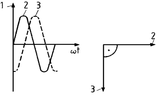
Fig 3: Windings spatially shifted by 90 degrees
Key Takeaways:
1. Four half coils are positioned spatially within 90 degrees on the circumference.
1. The word Pulsating means that the field builds up in one direction falls to zero and then builds up in the opposite direction. Under these conditions, the rotor of an induction motor does not rotate.
2. A pulsating magnetic field is produced, when the stator winding of the single-phase induction motor shown below is energised by a single phase supply.
3. The double revolving field theory of a single phase induction motor states that a pulsating magnetic field is resolved into two rotating magnetic fields.
4. They are equal in magnitude but opposite in directions.
5. The induction motor responds to each of the magnetic fields separately.
6. The net torque in the motor is equal to the sum of the torque due to each of the two magnetic fields.
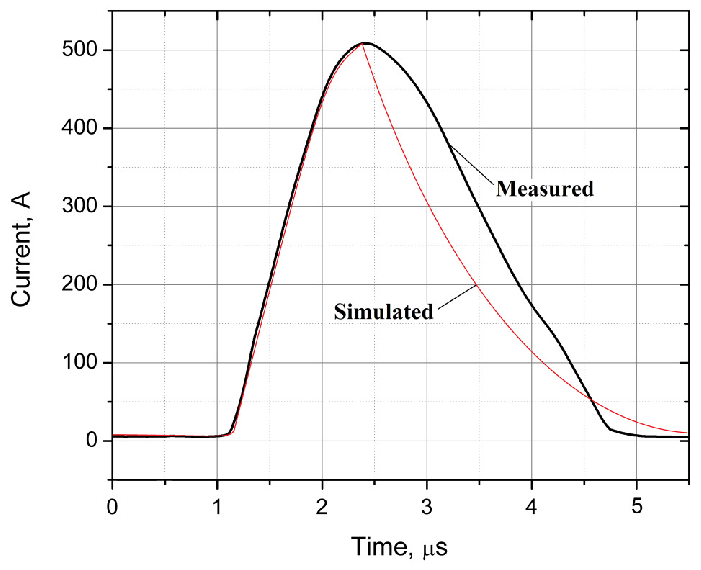
Fig 4 Graph of pulsating magnetic field
Key takeaways:
1. The induction motor responds to each of the magnetic fields separately.
2. The net torque in the motor is equal to the sum of the torque due to each of the two magnetic fields.
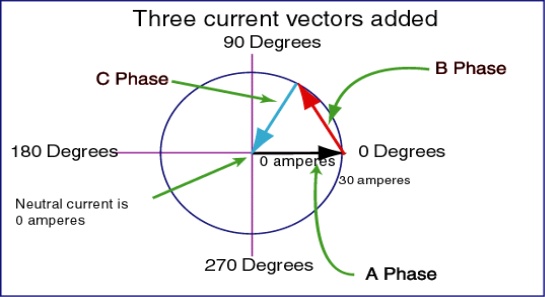
Fig 5: windings spatially shifting by 120 degrees in (quadrant)
1. In principle, any power generator has a rotor with magnets and coil on the periphery, one rotation of rotor is one cycle of 360 degrees.
2. Suppose the generator has one magnet and one coil, then as the magnet/rotor rotates one turn, the voltage generated in the coil gradually rises and reaches peak (max) when the coil comes closest to the magnet and reduces gradually as the magnet moves away.
3. Suppose we connect the bulb then the flicker rate is clearly visible. This is called 360 deg, single phase AC.
4. Now, suppose the generator has two magnets and two coils placed equidistantly, then the flicker rate is increased, it is 2-phase, 360/2=180 degrees AC.
5. Say generator has 3 magnets and 3 coils placed equidistantly, then the flicker rate is much increased; it is 3 phase with 360/3=120 degrees AC.
6. If we have 4 magnets and 4 coils placed equidistantly then the flicker rate is much more increased (not visible), then it is 4-phase with 360/4=90 degrees, 4-phase AC.
7. In practice, 3-phase is much more suitable for design.
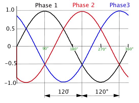
Fig 6: Phase shift of windings by 120 degree in wave
Key takeaways:
1. One rotation of rotor is one cycle of 360 degrees.
2. If we have 4 magnets and 4 coils placed equidistantly then the flicker rate is much more increased.
1. A rotating magnetic field is the resultant magnetic field produced by a system of coils symmetrically placed and supplied with polyphase currents.
2. A rotating magnetic field can be produced by a poly-phase (two or more phases) current or by a single phase current provided that, in the latter case, two field windings are supplied and are so designed that the two resulting magnetic fields generated thereby are out of phase.
3. When we apply a three-phase supply to a three-phase distributed winding of a rotating machine, a rotating magnetic field is produced which rotates in synchronous speed.
4. For that, we will first imagine one stator of an electric motor where three-phase winding is physically distributed in the stator core in such a manner that winding of each phase is separated from other by 120o in space.
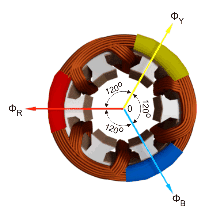
Fig 7. Revolving magnetic field in core
5. Although the vector sum of three currents in a balanced three-phase system is zero at any instant, but the resultant of the magnetic fields produced by the currents is not zero rather it will have a constant non-zero value rotating in space in respect to time.
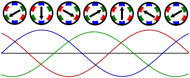
Fig 8. Direction and wave graph of revolving magnetic field
Key Takeaways:
1. Two field windings are supplied and are so designed that the two resulting magnetic fields generated thereby are out of phase.
2. Vector sum of three currents in a balanced three-phase system is zero at any instant, but the resultant of the magnetic fields produced by the currents is not zero
References:
1. A. E. Fitzgerald and C. Kingsley, "Electric Machinery”, McGraw Hill Education,2013.
2. M. G. Say, “Performance and design of AC machines”, CBS Publishers,2002.
3. P. S. Bimbhra, “Electrical Machinery”, Khanna Publishers,2011.
4. I. J. Nagrath and D. P. Kothari, “Electric Machines”, McGraw Hill Education,2010.
5. A. S. Langsdorf, “Alternating current machines”, McGraw Hill Education,1984.
6. P. C. Sen, “Principles of Electric Machines and Power Electronics”, John Wiley & Sons,2007.