Unit - 3
Three Phase Induction Motor
3.1.1 Construction of squirrel cage induction motor
1. Squirrel cage motor is one of the types of induction motors. To generate motion, it hardens electromagnetism. As the output shaft is connected to the rotor inner component which is looking like a cage. Hence it is called a squirrel cage.
2. The two-end caps i.e, circular are joined by rotor bars. These are acted based on the EMF i.e, generated by the stator. This EMF is also generated outer housing that is made of laminated metal sheets and wire coiling.
The two main parts of any type of induction motor are the stator and the rotor. The squirrel cage is a simple method of pulling an electromagnetic induction effect.
1. Parts that are required for the construction of squirrel cage induction motor are stator, rotor, fan, bearings.
2. The stator consists of mechanically and electrically 120 degrees apart three-phase winding with metal housing and core. To provide the path of low reluctance for flux generated by AC current, the winding is mounted on the laminated iron core.
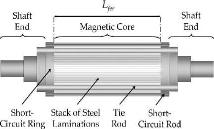
Fig 1: Squirrel cage induction motor
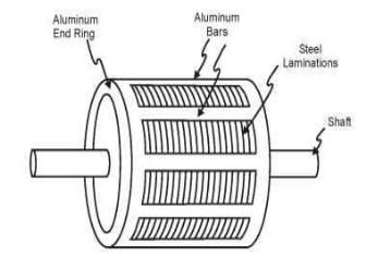
Fig 2: EXT part of squirrel cage induction motor
3. Rotor converts given electrical energy into mechanical output.
4. The shaft, a core, short-circuited copper bars are the parts of the rotor. To avoid hysteresis and eddy currents that are leading to power loss, the rotor is laminated.
5. And I order to prevent cogging, conductors are skewed which also helps to give a good transformation ratio.
6. A fan attached at the back of the rotor for heat exchange helps in maintaining under a limit of the temperature of the motor. For the smooth rotation, bearings are provided in the motor.
3.1.2 Types of squirrel cage induction motor
1. Class-A Design
These types of motors have low resistance, reactance, slip, and higher efficiency at full load. The main disadvantage is the high starting current which is 5 to 8 times of full-load current at rated voltage. These motors are widely used in small ratings for machine tools, centrifugal pumps, fans, blowers, etc.
2. Class B Design
These motors have high reactance and operate 5-150KW range. These motors can be replaced with class A motors for new installations because of their characteristics which are similar to Class A motors and have the same starting current. (around 5 times the full-load current at rated voltage).
3. Class C Design
These motors are known as double cage motors that high starting torque with a low starting current. Applications of class C motors are, driving air compressors, conveyors, reciprocating pumps, crushers, mixers, large refrigerating machines, etc.
4. Class D Design
These motors are squirrel cage motors with high resistance. Hence, they give high starting torque with a low starting current. These motors have low operating efficiency and are limited to drive intermittent loads involved in high accelerating duty and high-impact loads such as punch presses, shears, bulldozers, small hoists, etc.
5. Class E Design
These motors operate with low starting torque, normal starting current, and also low slip at rated load.
6. Class F Design
These motors are operated with low starting torque, low starting current, and normal slip.
Key takeaways
1. As the output shaft is connected to the rotor inner component which is looking like a cage. Hence it is called a squirrel cage.
2. To avoid hysteresis and eddy currents that are leading to power loss, the rotor is laminated.
3. For the smooth rotation, bearings are provided in the motor
3.2.1 Construction of Slip ring induction motor
1. A slip ring induction motor is referred to as an asynchronous motor as the speed at which it operates is not equal to the synchronous speed of a rotor. The rotor of this type of motor is wound type.
2. It comprises a cylindrical laminated steel core and a semi-closed groove at the outer boundary to accommodate a 3-phase insulated winding circuit.
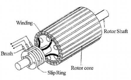
Fig 3. Slip ring induction motor
The construction includes two parts: Stator and Rotor.
1. Stator
The stator of this motor comprises various slots that are arranged to support the construction of a 3-phase winding circuit connecting to a 3-phase AC source.
2. Rotor
The rotor of this motor consists of a cylindrical core with steel laminations. Besides this, the rotor has parallel slots to accommodate 3-phase windings. The windings in these slots are arranged at 120 degrees to each other. This arrangement can reduce noise and avoid irregular pausing of a motor.
Key takeaways:
1. It comprises a cylindrical laminated steel core and a semi-closed groove at the outer boundary to accommodate a 3-phase insulated winding circuit.
2.. The windings in these slots are arranged at 120 degrees to each other. This arrangement can reduce noise and avoid irregular pausing of a motor.
Torque Slip Characteristics of Three Phase Induction Motor
1. The torque slip curve for an induction motor gives us information about the variation of torque with the slip.
2. The slip is defined as the ratio of the difference of synchronous speed and actual rotor speed to the synchronous speed of the machine.
3. The variation of slip can be obtained with the variation of speed that is when speed varies the slip will also vary and the torque corresponding to that speed will also vary.
The curve can be described in three modes of operation-
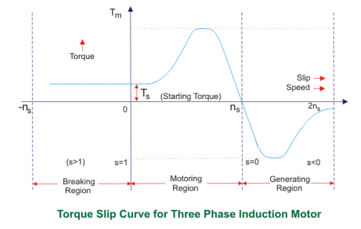
Fig 4. Torque slip characteristics
The torque-slip characteristic curve can be divided roughly into three regions:
1. Low slip region
2. Medium slip region
3. High slip region
3.3.1 Motoring Mode
1. In this mode of operation, supply is given to the stator sides and the motor always rotates below the synchronous speed. The induction motor torque varies from zero to full load torque as the slip varies. The slip varies from zero to one. It is zero at no load and one at standstill. From the curve, it is seen that the torque is directly proportional to the slip.
2. That is, more is the slip, more will be the torque produced, and vice-versa. The linear relationship simplifies the calculation of motor parameters to great extent.
3.3.2 Generating Mode
1. In this mode of operation induction motor runs above the synchronous speed and it should be driven by a prime mover.
2. The stator winding is connected to a three-phase supply in which it supplies electrical energy. Actually, in this case, the torque and slip both are negative so the motor receives mechanical energy and delivers electrical energy.
3. Induction motor is not much used as a generator because it requires reactive power for its operation.
4. That is, reactive power should be supplied from outside and if it runs below the synchronous speed by any means, it consumes electrical energy rather than giving it at the output. So, as far as possible, induction generators are generally avoided.
3.3.3 Braking Mode
1. In the Braking mode, the two leads or the polarity of the supply voltage is changed so that the motor starts to rotate in the reverse direction and as a result, the motor stops.
2. This method of braking is known as plugging. This method is used when it is required to stop the motor within a very short period.
3. The kinetic energy stored in the revolving load is dissipated as heat. Also, the motor is still receiving power from the stator which is also dissipated as heat.
4. So as a result of which motor develops enormous heat energy. For this stator is disconnected from the supply before the motor enters the braking mode.
5. If the load which the motor drives accelerates the motor in the same direction as the motor is rotating, the speed of the motor may increase more than synchronous speed. In this case, it acts as an induction generator that supplies electrical energy to the mains which tend to slow down the motor to its synchronous speed, in this case, the motor stops. This type of breaking principle is called dynamic or regenerative breaking.
Key takeaways:
1. The variation of slip can be obtained with the variation of speed that is when speed varies the slip will also vary and the torque corresponding to that speed will also vary.
2. The induction motor torque varies from zero to full load torque as the slip varies. The slip varies from zero to one.
3. Induction motor is not much used as a generator because it requires reactive power for its operation.
4.. If load which the motor drives accelerates the motor in the same direction as the motor is rotating, the speed of the motor may increase more than synchronous speed
1. Maximum torque
The developed torque is maximum when the rotor resistance per phase is equal to the rotor reactance per phase under running conditions.
2. Starting torque
Starting torque is the torque transferred by the shaft coupling during run-up (see Start-up process). It is calculated based on the ratio of power (P) to angular velocity (ω) and is represented as a rotational speed function.
Key takeaways
1. It is calculated based on the ratio of power (P) to angular velocity (ω) and is represented as a rotational speed function.
1. The equivalent circuit of any machine shows the various parameter of the machine such as its Ohmic losses and also other losses.
2. The losses are modeled just by inductor and resistor.
3. The copper losses have occurred in the windings so the winding resistance is taken into account. Also, the winding has inductance for which there is a voltage drop due to inductive reactance, and also a term called power factor comes into the picture. There are two types of equivalent circuits in the case of a three-phase induction motor-
Exact Equivalent Circuit
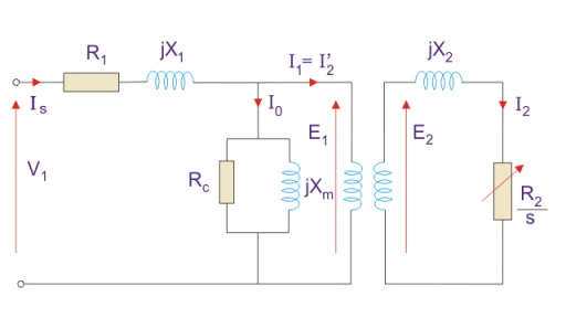
Fig 5 Equivalent Circuit
Here, R1 is the winding resistance of the stator.
X1 is the inductance of the stator winding.
Rc is the core loss component.
XM is the magnetizing reactance of the winding.
R2/s is the power of the rotor, which includes output mechanical power and copper loss of the rotor.
If we draw the circuit with referred to the stator then the circuit will look like-
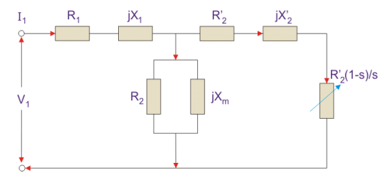
Fig 6. Equivalent circuit
Here all the other parameters are the same except-
R2’ is the rotor winding resistance referred to as stator winding.
X2’ is the rotor winding inductance referred to as stator winding.
R2 (1 – s) / s is the resistance that shows the power which is converted to mechanical power output or useful power. The power dissipated in that resistor is the useful power output or shaft power.
4. The approximate equivalent circuit is drawn just to simplify our calculation by deleting one node. The shunt branch is shifted towards the primary side.
5. This has been done as the voltage drop between the stator resistance and inductance is less and there is not much difference between the supply voltage and the induced voltage.
However, this is not appropriate due to the following reasons-
1. The magnetic circuit of the induction motor has an air gap so the exciting current is larger compared to the transformer so an exact equivalent circuit should be used.
2. The rotor and stator inductance is larger in the induction motor.
3. In an induction motor, we use distributed windings.
4. This model can be used if the approximate analysis has to be done for large motors. For smaller motors, we cannot use this.
Key takeaways:
1. The winding has inductance for which there is a voltage drop due to inductive reactance and also a term called power factor comes into the picture.
2. This has been done as the voltage drop between the stator resistance and inductance is less and there is not much difference between the supply voltage and the induced voltage.
3. The magnetic circuit of the induction motor has an air gap so the exciting current is larger compared to the transformer so an exact equivalent circuit should be used.
1. As we know the principle of induction motor is very similar to the transformer with some differences.
2. An induction motor at standstill condition is similar to a transformer at no-load condition. Therefore, the method of drawing the induction motor phasor diagram is also the same as that of a transformer phasor diagram.
3. In this we will discuss the phasor diagram of induction motor at standstill condition and full load slip.
3.6.1 Induction Motor Phasor Diagram at Standstill Condition:
Before going into the phasor diagram, there are some important points to be taken care of:
Per phase value of induced emf E1 in the stator winding is given below
E1 = √2πf1kw1N1Ø
Where f1 = supply frequency
N1 = Number of series turns per phase
Ø = resultant air-gap flux per pole
Kw1 = Stator winding factor
Per phase value of induced emf E2 in rotor winding is given as
E2 = √2πf2kw2N2Ø
Where f2 = frequency of induced emf in rotor = sf1
N2 = Number of series turns per phase
Ø = resultant air-gap flux per pole
Kw2 = Rotor winding factor
1. Total air gap mmf Fr of induction motor is the sum of stator mmf (F1) and rotor mmf (F2).
2. Magnetizing current Im took by the stator winding from the supply always remains in phase with the resultant flux Ø. The induced emf always lags behind the resultant flux Ø by 90°.
3. Now we are at a stage to draw the induction motor phasor diagram. Let us take the resultant air-gap flux Ø as the reference. This flux Ø will be in phase with the resultant mmf Fr. Also, the induced emf E1 and E2 in stator and rotor winding will lag behind the Ø by 90°. This is shown in the below phasor diagram of the induction motor.
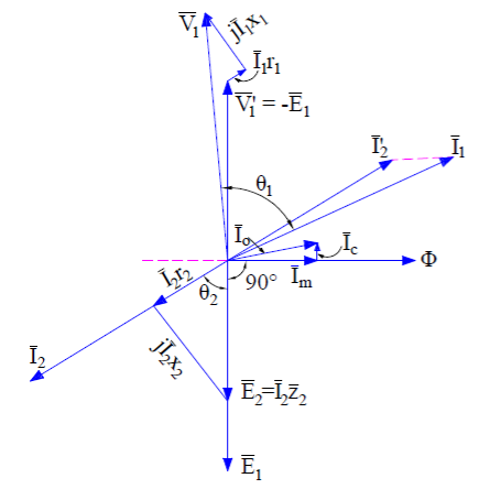
Fig 7. Phasor diagram of induction motor
4. Since the rotor mmf counteracts the stator produced mmf as per Lenz's law, therefore stator takes extra current from supply to counterbalance the effect of rotor current. Therefore under normal condition,
Stator mmf = Rotor mmf
N1’I2’ = N2’I2
Where N1’ and N2’ are the effective stator and rotor turns per phase.
5. This component of stator current is called the load component. In addition to the load component, the stator also takes magnetizing current Im to build magnetic flux in the air gap.
6. Thus the total stator current I1 = I2’ + Im. This is shown in the above phasor diagram. I2’ is shown the opposite to the rotor current I2 for the reason discussed above.
7. At standstill condition, E2 = I2 (r2 + jx2). The core loss component of stator current Ic is in phase with V1’ or –E1. At standstill condition, the friction and windage loss is zero, therefore the stator no-load current is given as
I0 = Im + Ic
Since stator applied voltage V1 must balance the stator back emf V1’ or -E1, stator impedance drop I1(r1 + jx1), therefore we can write
V1 = V1’ + I1(r1 + jx1) ……(1)
A similar equation exists for rotor circuit and can be written as
E2 = I2 (r2 + jx2) ……..(2)
8. The above equations are applied for drawing the induction motor phasor diagram as shown in the above figure. It can be easily seen from the above phasor diagram that, the power factor (cosɵ) of the induction motor at starting is very poor as ɵ is large.
3.6.2 Induction Motor Phasor Diagram at Full Load Slip:
1. At full load, the slip s of induction is low. The stator voltage equation (1) does not change when the motor is loaded. But the rotor voltage equation changes with slip. The rotor induced voltage at any slip s becomes sE2 and the rotor circuit reactance becomes sx2. Therefore,
SE2 = I2 (r2 + jsx2)
2. The above rotor equation when implemented, the induction motor phasor diagram will become different from the phasor at standstill condition. The induction motor phasor at full load slip s is shown below.
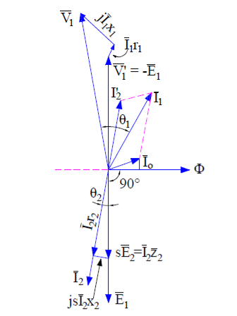
Fig 8. Phasor diagram at full load
3. Since at full load condition, some friction and windage loss will exist. This means that the stator will have to draw some extra current from the supply main to provide this additional loss.
4. Therefore the total no-load current I0 taken by stator is the sum current Ifc and Im. It can be seen from the above phasor diagram that the power factor of the induction motor improves.
5. Generally at full load the power factor ranges between 0.8 to 0.9.
Key takeaways:
1. The method of drawing the induction motor phasor diagram is also the same as that of a transformer phasor diagram.
2. Magnetizing current Im took by the stator winding from the supply always remains in phase with the resultant flux Ø. The induced emf always lags behind the resultant flux Ø by 90°.
Two types of losses occur in a three-phase induction motor. These losses are,
1 Constant or fixed losses,
2 Variable losses.
3. Constant or Fixed Losses
3.7.1 Constant or fixed losses
Constant losses are those losses that are considered to remain constant over the normal working range of the induction motor. The fixed losses can be easily obtained by performing a no-load test on the three-phase induction motor. These losses are further classified as-
1. Iron or core losses,
2. Mechanical losses,
3. Brush friction losses.
1. Iron or Core Losses
1. Iron or core losses are further divided into hysteresis and eddy current losses. Eddy current losses are minimized by using lamination on the core.
2. Since by laminating the core, the area decreases, and hence resistance increases, which results in a decrease in eddy currents. Hysteresis losses are minimized by using high-grade silicon steel.
3. The core losses depend upon the frequency of the supply voltage. The frequency of stator is always supply frequency, f and the frequency of rotor is slip times the supply frequency, (sf) which is always less than the stator frequency.
4. For stator frequency of 50 Hz, rotor frequency is about 1.5 Hz because under normal running conditions slip is of the order of 3 %. Hence the rotor core loss is very small as compared to stator core loss and is usually neglected in running conditions.
2. Mechanical and Brush Friction Losses
1. Mechanical losses occur at the bearing and brush friction loss occurs in the wound rotor induction motor. These losses are zero at the start and with an increase in speed these losses increase.
2. In a three-phase induction motor the speed usually remains constant.
3. Hence these losses almost remain constant.
3.7.2 Variable Losses
1. These losses are also called copper losses. These losses occur due to the current flowing in stator and rotor windings.
2. As the load changes, the current flowing in rotor and stator winding also changes, and hence these losses also change. Therefore these losses are called variable losses.
3. The copper losses are obtained by performing a blocked rotor test on a three-phase induction motor. The main function of an induction motor is to convert electrical power into mechanical power.
4. During this conversion of electrical energy into mechanical energy the power flows through different stages.
5. This power flowing through different stages is shown by the power flow diagram. As we all know the input to the three-phase induction motor is a three-phase supply.
6. So, the three-phase supply is given to the stator of the three-phase induction motor.
Let, Pin = electrical power supplied to the stator of three-phase induction motor,
VL = line voltage supplied to the stator of three-phase induction motor,
IL = line current,
Cosφ = power factor of the three-phase induction motor.
Electrical power input to the stator, Pin = √3VLILcosφ
A part of this power input is used to supply stator losses which are stator iron loss and stator copper loss. The remaining power i.e (input electrical power – stator losses) is supplied to the rotor as rotor input.
So, rotor input P2 = Pin – stator losses (stator copper loss and stator iron loss).
7. Now, the rotor has to convert this rotor input into mechanical energy but this complete input cannot be converted into mechanical output as it has to supply rotor losses. As explained earlier the rotor losses are of two types rotor iron loss and rotor copper loss.
8. Since the iron loss depends upon the rotor frequency, which is very small when the rotor rotates, so it is usually neglected. So, the rotor has only rotor copper loss.
9. Therefore the rotor input has to supply these rotor copper losses. After supplying the rotor copper losses, the remaining part of Rotor input, P2 is converted into mechanical power, Pm.
10. Now this mechanical power developed is given to the load by the shaft but there occur some mechanical losses like friction and windage losses. So, the gross mechanical power developed has to be supplied to these losses. Therefore the net output power developed at the shaft, which is finally given to the load is Pout.
Pout = Pm – Mechanical losses (friction and windage losses).
Pout is called the shaft power or useful power.

Fig 9. Power flow diagram
Key takeaways:
1. The core losses depend upon the frequency of the supply voltage. The frequency of stator is always supply frequency
2. These losses are zero at the start and with an increase in speed these losses increase.
3. The copper losses are obtained by performing a blocked rotor test on a three-phase induction motor. The main function of an induction motor is to convert electrical power into mechanical power.
The efficiency of 3 phase induction motor:
Efficiency is defined as the ratio of output to that of input

Rotor efficiency of 3 phase induction motor

Gross mechanical power developed /rotor input

Three-phase induction motor efficiency

Three-phase induction motor efficiency

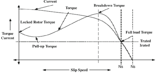
Fig 15. Variation of parameters in torque-speed characteristics
1. In a previous article for torque-speed characteristics, we studied the different parameters related to that curve.
2. Suppose if we have such a rotor that has a higher value of the rotor resistance Rr due to this higher value of the resistance the starting torque will also larger, as torque is higher so the slip will also higher.
As we know that this equation.
P conv = (1-s) PAG
3. Due to the higher value of the slip, the power converted from the electrical to mechanical will have less value, due to less power conversion the efficiency of the motor will decrease.
4. From that, we can conclude that such a motor that has higher rotor resistance, has larger starting torque but less efficiency.
5. If the resistance of the rotor is less than the starting torque will also less but the efficiency of the motor will be larger than the motor that has a high value of the rotor’s resistance.
6. The manufacturer of the motor always tries to cooperate among the differing requirements of higher initial torque and suitable efficiency.
7. The solution for this is that if we put some additional resistance in the rotor of the wound motor during its starting for higher torque then during its normal working remove this resistance for good efficiency.
8. But there is a problem with this condition that the wound rotor motor is costly, its repairing price is also larger, need a multifaceted automatic control circuitry than cage rotor motors.
9. Similarly, it is sometimes significant to entirely cover a motor when it is sited in a risky or fiery atmosphere, and this is calmer to do with an entirely self-contained rotor.
10. It would be pleasing to add additional rotor resistance at initial and to eliminate it during normal operation without automatic control circuitry.
11. In the given figure you can see the 2 wound rotor motors characteristic curves, one motor has a high resistance rotor, and the second has less resistance rotor.
12. At a higher slip value, the anticipated motor should act like the higher-resistance wound-rotor motor curve, and at less slip, it should act like the less-resistance wound-rotor motor curve.
Key takeaways:
1. As torque is higher so the slip will also higher.
2. If the resistance of the rotor is less than the starting torque will also less but the efficiency of the motor will be larger than the motor that has a high value of the rotor’s resistance.
We classify starting methods for squirrel cage induction motor into two types based on voltage. The two types are:
1. Full voltage starting method
2. Reduced voltage method for starting squirrel cage induction motor.
3.10.1 Full Voltage Starting Method for Squirrel Cage Induction Motor
In this type, we have only one method of starting.
1. Direct on Line Starting Method
1. This method is also known as the DOL method for starting the three-phase squirrel cage induction motor. In this method, we directly switch the stator of the three-phase squirrel cage induction motor on to the supply mains.
2. The motor at the time of starting draws a very high starting current (about 5 to 7 times the full load current) for a very short duration.
3. The amount of current drawn by the motor depends upon its design and size. But such a high value of current does not harm the motor because of the rugged construction of the squirrel cage induction motor.
4. Such a high value of current causes sudden undesirable voltage drop in the supply voltage. A live example of this sudden drop of voltage is the dimming of the tube lights and bulbs in our homes at the instant of starting of refrigerator motor.
5. Now let us derive the expression for starting torque in terms of full load torque for the direct online starter. We have various quantities that involved in the expression for the starting torque are written below: We define Ts as starting torque
Tf as the full load torque
If as per phase rotor current at full load
Is as per phase rotor current at the time of starting
Sf as full load slip
Ss as starting slip
R2 as rotor resistance
Ws as the synchronous speed of the motor
Now we can directly write the expression for the torque of the induction motor as

From the help of the above expression, we write the ratio of starting torque to full load torque as

Here we have assumed that the rotor resistance is constant and it does not vary with the frequency of the rotor current.
3.10.2 Reduced voltage method for starting squirrel cage induction motor
In the reduced voltage method, we have three different types of starting method and these are written below:
1. Stator resistor starting method
2. Autotransformer staring method
3. Star delta starting method
Now let us discuss each of these methods in detail.
1. Stator Resistor Starting Method
Given below is the figure for the starting resistor method:
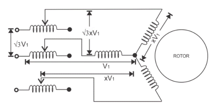
Fig 16. Stator resistor
1. In this method we add a resistor or a reactor in each phase as shown in the diagram (between the motor terminal and the supply mains). Thus by adding a resistor we can control the supply voltage.
2. Only a fraction of the voltage (x) of the supply voltage is applied at the time of starting of the induction motor. The value of x is always less than one.
3. Due to the drop in the voltage the starting torque also decreases. We will derive the expression for the starting torque in terms of the voltage fraction x to show the variation of the starting torque with the value of x.
4. As the motor speeds up the reactor or resistor is cut out from the circuit and finally, the resistors are short-circuited when the motor reaches its operating speed.
5. Now let us derive the expression for starting torque in terms of full load torque for the stator resistor starting method. We have various quantities that involved in the expression for the starting torque are written below: we define Ts as starting torque
Tf as the full load torque
If as per phase rotor current at full load
Is as per phase rotor current at the time of starting
Sf as full load slip
Ss as starting slip
R2 as rotor resistance
Ws as the synchronous speed of the motor
Now we can directly write the expression for the torque of the induction motor as

From the help of the above expression, we write the ratio of starting torque to full load torque as

Here we have assumed that the rotor resistance is constant and it does not vary with the frequency of the rotor current. From the above equation, we can have the expression for the starting torque in terms of the full load torque.
6. Now at the time of starting the per phase voltage is reduced to xV1, the per phase starting current is also reduced to xIs. On substituting the value of Is as xIs in the equation We have


7. This shows the variation of the starting torque with the value of x. Now there are some considerations regarding this method. If we add a series resistor then the energy losses are increased so it’s better to use a series reactor in place of a resistor because it is more effective in reducing the voltage however series reactor is more costly than the series resistance.
2. Auto Transformer Starting Method
1. As the name suggests in this method we connect the auto transformer in between the three-phase power supply and the induction motor as shown in the given diagram:
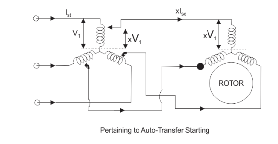
Fig 17. Stating of autotransformer
2. The autotransformer is a step-down transformer hence it reduces the per phase supply voltage from V1 to xV1. The reduction in voltage reduces current from Is to xIs.
3. After the motor reaches its normal operating speed, the autotransformer is disconnected and then full line voltage is applied.
3. Now let us derive the expression for starting torque in terms of full load torque for the autotransformer starting method. We have various quantities that involved in the expression for the starting torque are written below:
We define Ts as starting torque
Tf as the full load torque
If as per phase rotor current at full load
Is as per phase rotor current at the time of starting
Sf as full load slip
Ss as starting slip
R2 as rotor resistance
Ws as the synchronous speed of the motor
Now we can directly write the expression for the torque of the induction motor as

From the help of the above expression, we write the ratio of starting torque to full load torque as


4. Here we have assumed that the rotor resistance is constant and it does not vary with the frequency of the rotor current. From the above equation, we can have the expression for the starting torque in terms of the full load torque.
5. Now at the time of starting the per phase voltage is reduced to xV1, the per phase starting current is also reduced to xIs. On substituting the value of Is as xIs in equation 1. We have
This shows the variation of the starting torque with the value of x.
3. Star-Delta Starting Method
The connection diagram is shown below for the star-delta method,
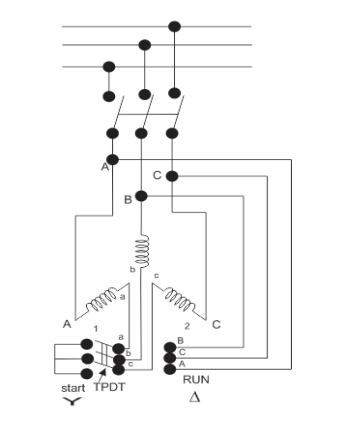
Fig 18. Star delta connection
1. This method is used for the motors designed to operate in delta connected winding. The terminals are marked for the phases of the stator are shown above. Now let us see this method works.
2.The stator phases are first connected to the star with the help of a triple pole double throw switch (TPDT switch) in the diagram the position is marked as 1 then after this when the steady-state speed is reached the switch is thrown to position 2 as shown in the above diagram.
3. Now, let analyze the working of the above circuit. In the first position, the terminals of the motor are short-circuited and in the second position from the diagram the terminal a, b and c are respectively connected to B, C, and A.
4. Now let us derive the expression for starting torque in terms of full load torque for the star-delta starting method. We have various quantities that involved in the expression for the starting torque are written below
Tf as the full load torque
Ts as starting torque
If as per phase rotor current at full load
Is as per phase rotor current at the time of starting
Sf as full load slip
Ss as starting slip
R2 as rotor resistance
Ws as the synchronous speed of the motor
Now we can directly write the expression for the torque of the induction motor as

From the help of the above expression, we write the ratio of starting torque to full load torque as

5. Here we have assumed that the rotor resistance is constant and it does not vary with the frequency of the rotor current. Let us assume the line voltage to be Vl then the per phase starting current when connected in star position is Iss which is given by

When the stator is in delta connected position we have starting current

From the above equation we have

6. This shows that the reduced voltage method has the advantage of reducing the starting current but the disadvantage is that all these methods of reduced voltage cause the objectionable reduction in the starting torque.
Key takeaways:
1. In DOL the amount of current drawn by the motor depends upon its design and size
2. In the stator resistor starting method Due to the drop in the voltage the starting torque also decreases.
3. In autotransformer starting method. After the motor reaches its normal operating speed, the autotransformer is disconnected and then full line voltage is applied.
4.star delta starting method is used for the motors designed to operate in delta connected winding.
1. When it comes to controlling an electric machine by electric drivers braking is a very important term because it helps to decrease the speed of the motor according to will and necessity. The braking of induction motors can be classified mainly into three types
3.11.1 Regenerative braking.
1. Plugging or reverse voltage braking
2. Dynamic braking which can be further classified as
3. AC dynamic braking
4. Self-excited braking using capacitors
5. DC dynamic braking
6. Zero sequence braking
To explain that regeneration braking for induction motor, we can take help of the equation
1. Here, θs is the phase angle between the stator voltage and stator current, the simple words whenever this phase angle exceeds 90o (i.e θs>90o) regenerative braking can take place.
2. To explain this more clearly and easily we can say that whenever the speed of the rotor exceeds synchronous speed, regeneration braking occurs.
3. That is because whenever the rotor rotates at a speed more than synchronous speed there is a reverse field occurs which opposes the normal rotation of the motor and therefore braking takes place.
4. Main disadvantage of this type of braking is that the speed of the motor has to exceed synchronous speed which may not be possible every time. To acquire regenerative braking at a lower speed than synchronous speed, a variable frequency source can be used.
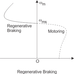
Fig 19. Braking graph
6. Plugging of induction motors is done by interchanging any two of the supply terminals. When the terminals have reversed the operation of the machine changes from motoring to plugging.
7. From a technical point of view and for better understanding it can be said that the slip changes from‘s’ to (2-s), which indicates that due to reversal of the terminals the torque also changes its direction and braking occurs.
8. The first classification of dynamic braking of induction motors is AC dynamic braking any one of the supply phases is disconnected from the supply and then it is either kept open or connected with the other phase.
9. The first type is known as two lead connections and the second one is known as three lead connections.
10. To understand this braking method we can assume the system to be a single-phase system. Now the motor can be considered to be fed by positive and negative sequence voltages. That’s why when the rotor resistance is high the net torque is negative and braking can be acquired.
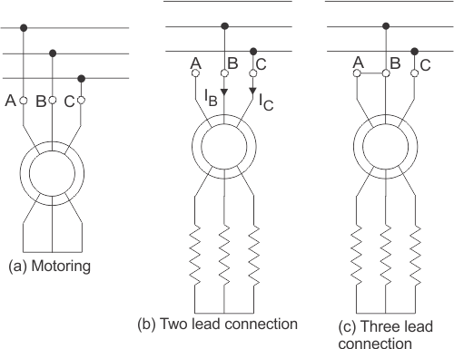
Fig 20. Braking systems in dynamic induction
11. Sometimes capacitors are kept permanent by connected across the supply terminals of the motor. This is called self-excited braking using capacitors of induction motors.
12. This type of braking works mainly by the property of the capacitors to store energy. Whenever the motor is disconnected from the supply the motor starts to work as a self-excited induction generator, the power comes from the capacitors connected across the terminals.
13. The values of the capacitor are so chosen that they are sufficient to make the motor work as an induction generator after being disconnected from the supply. When the motor works as an induction generator the produced torque opposes the normal rotation of the motor and hence braking takes place.
3.11.2 Speed control of induction motor
Speed control of induction motors can be done in six methods which are
1. Pole changing
2. Stator voltage control
3. Supply frequency control
4. Eddy current coupling
5. Rotor resistance control
1. We know that the speed of the induction motor is inversely proportional to several poles. So it is possible to increase or decrease the speed of the induction motor if the number of the poles is decreased or increased respectively.
2. The motor in which the provision of changing the number of poles is present, they are called ‘pole changing motor’ or ‘multi-speed motor’.
3. Another method of controlling the speed of induction motor drives is stator voltage control. Stator voltage is directly responsible for the rotating speed of the rotor.
4. Torque is proportional to voltage squared and the current is proportional to the voltage. So, if the stator voltage is reduced the speed reduces, and similarly if the stator voltage is increased the speed also increases.
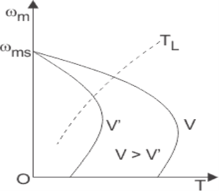
Fig 21. Speed control graph
5. The speed of an induction motor is proportional to the product of the supply frequency and air gap flux.
6. But as there is a chance of magnetic saturation while decreasing the supply frequency, that’s why not only the frequency but the v/f (i.e the ratio of supply voltage and frequency) is controlled and this ratio is tried to be kept constant. And if the speed is needed to be changed the ratio of v/f is changed accordingly.
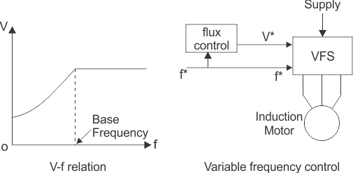
Fig 22. Voltage and frequency relation graph
7. The eddy current speed control method is done by placing an eddy current clutch between an induction motor is running at a fixed speed and the variable speed load. Now, what is this eddy current clutch?
8. It is nothing but an induction motor drive in which both the stator and the rotor are allowed to rotate. The rotor is coupled with the main induction motor.
9. When eddy currents are produced in the rotor drum, their interaction with the stator field and torque is produced which rotates the main motor. By controlling the DC current through the stator winding the speed of the motor can be controlled.
10. Depending on the rotor resistance, the speed of the rotor falls or increases. The variation of speed-torque characteristics with respect to change in rotor resistance is shown in the figures below.
11.This speed controlling method is better than many other methods because of its low cost
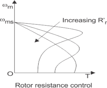
Fig 23. Resistance control graph
Key takeaways:
1. Torque is proportional to voltage squared and the current is proportional to the voltage. So, if the stator voltage is reduced the speed reduces, and similarly if the stator voltage is increased the speed also increases.
2. The speed of an induction motor is proportional to the product of the supply frequency and air gap flux.
3. By controlling the DC current through the stator winding the speed of the motor can be controlled.
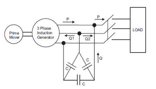
Fig 24. Generator diagram
Induction machines are sometimes used as a generator. These are known as induction generators or asynchronous generators. So under what conditions an induction machine will behave as an induction generator?
An induction machine will behave as an induction generator when:
1. Slip becomes negative due to this the rotor current and rotor emf attains negative value.
The prime mover torque becomes the opposite of electric torque.
2. Now let us discuss how we can achieve these conditions. Suppose that an induction machine is coupled with the prime mover whose speed can be controlled.
3. If the speed of the prime mover is increased such that the slip becomes negative (i.e. speed of the prime mover becomes greater than the synchronous speed).
4. Due to this, all the conditions that we have mentioned above will become fulfilled and the machine will behave like an induction generator. Now if the speed of the prime mover is further increased such that it exceeds the negative maximum value of the torque produced then the generating efficiency of the generator vanishes.
5. Clearly, the speed of the induction generator during the whole operation is not synchronous, therefore the induction generator is also called a synchronous generator.
6.An induction generator is not a self-excited machine. Therefore To develop the rotating magnetic field, requires magnetizing current and reactive power. The induction generator obtains its magnetizing current and reactive power from various sources like the supply mains or it may be another synchronous generator.
Key takeaways:
1. Slip becomes negative due to this the rotor current and rotor emf attains negative value. The prime mover torque becomes the opposite of electric torque.
2. To develop the rotating magnetic field, requires magnetizing current and reactive power
1. It is clear that an induction machine needs reactive power for excitation, regardless of whether it is operating as a generator or a motor. When an induction generator is connected to a grid, it takes reactive power from the grid. But what if we want to use an induction generator to supply a load without using an external source (e.g. Grid)?
2. A capacitor bank can be connected across the stator terminals to supply reactive power to the machine as well as to the load. When the rotor is rotated at enough speed, a small voltage is generated across the stator terminals due to residual magnetism. Due to this small generated voltage, capacitor current is produced which provides further reactive power for magnetization.
Key takeaways:
1. When the rotor is rotated at enough speed, a small voltage is generated across the stator terminals due to residual magnetism.
1. Doubly-fed electric machines also slip-ring generators are electric motors or electric generators, where both the field magnet windings and armature windings are separately connected to equipment outside the machine.
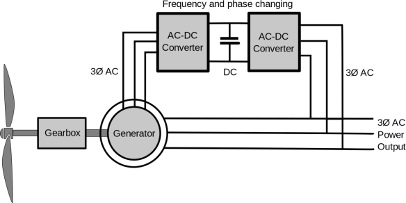
Fig 25. Doubly fed induction machine
2. Double-fed induction generator (DFIG), a generating principle widely used in wind turbines. It is based on an induction generator with a multiphase wound rotor and a multiphase slip ring assembly with brushes for access to the rotor windings.
3. The principle of the DFIG is that stator windings are connected to the grid and rotor winding are connected to the converter via slip rings and a back-to-back voltage source converter that controls both the rotor and the grid currents.
4. Thus rotor frequency can freely differ from the grid frequency (50 or 60 Hz). By using the converter to control the rotor currents, it is possible to adjust the active and reactive power fed to the grid from the stator independently of the generator's turning speed.
4. The control principle used is either the two-axis current vector control or direct torque control (DTC). DTC has turned out to have better stability than current vector control especially when high reactive currents are required from the generator.
5. The doubly-fed generator rotors are typically wound with 2 to 3 times the number of turns of the stator. This means that the rotor voltages will be higher and currents respectively lower.
6. Thus in the typical ±30% operational speed range around the synchronous speed, the rated current of the converter is accordingly lower which leads to a lower cost of the converter.
Key takeaways:
1. The principle of the DFIG is that stator windings are connected to the grid and rotor winding are connected to the converter via slip rings and a back-to-back voltage source converter that controls both the rotor and the grid currents.
2. DTC has turned out to have better stability than current vector control especially when high reactive currents are required from the generator.
3. The doubly-fed generator rotors are typically wound with 2 to 3 times the number of turns of the stator.
References:
1. A. E. Fitzgerald and C. Kingsley, "Electric Machinery”, McGraw Hill Education,2013.
2. M. G. Say, “Performance and design of AC machines”, CBS Publishers,2002.
3. P. S. Bimbhra, “Electrical Machinery”, Khanna Publishers,2011.
4. I. J. Nagrath and D. P. Kothari, “Electric Machines”, McGraw Hill Education,2010.
5. A. S. Langsdorf, “Alternating current machines”, McGraw Hill Education,1984.
6. P. C. Sen, “Principles of Electric Machines and Power Electronics”, John Wiley & Sons,2007.