Unit -1
Introduction to Power System Protection
The objective of power system protection is to isolate a faulty section of electrical power system from rest of the live system so that the rest portion can function satisfactorily without any severe damage due to fault current.
Actually circuit breaker isolates the faulty system from rest of the healthy system and these circuit breakers automatically open during fault condition due to its trip signal which comes from protection relay. The main philosophy about protection is that no protection of power system can prevent the flow of fault current through the system, it only can prevent the continuation of flowing of fault current by quickly disconnect the short circuit path from the system. For satisfying this quick disconnection the protection relays should have following functional requirements.
The following protection schemes are used in a power system-
a) Over Current Protection Scheme
b) Differential Protection Scheme
c) Distance Protection Scheme
d) Directional Protection Scheme
The nature of fault simply implies any abnormal condition which causes a reduction in the basic insulation strength between phase conductors, between phase conductor and earth or any earth screen surrounding the conductors. The reduction of the insulation is not considered as a fault until it produces some effect on the system i.e., until it results either in an excess current or in the reduction of the impedance between the conductors, between the conductor and earth to a value below the lowest load impedance normal to the circuit. Power systems mainly consist of generator; switch gear, transformer and distribution system. The probability of failure is more on the power system due to their greater length and exposure to atmosphere.
(a) Breakdown at normal voltage may occur on account of: i) The deterioration of insulation (ii) Damage due to unpredictable causes such as perching of birds, accidental short-circuiting by snakes, tree branches, etc.
(b) Breakdown may occur because of abnormal voltages: This may happen because of (i) switching surges (ii) surges caused by lightning. The present practice is to provide a high insulation level of the order 3 to 5 times the normal voltage, but still: (i) The pollution on an insulator string caused by deposited soot or cement dust in industrial area. (ii) Salt deposited wind borne see spray in coastal area. These will initially lower the insulation resistances and causes a small leakage current to be diverted, thus hastening the deterioration. Secondly, even if the insulation is enclosed, such as sheathed and armoured, the deterioration of the insulation occurs because of: (a) Ageing (b) Void formation in the insulation compound of underground cable due to unequal expansion and contractions caused by the rise and fall of temperature. Thirdly, insulation may be subjected to transient over voltages because of switching operation.
The voltage which rises at a rapid rate may achieve a peak value which approaches three times phase to neutral voltages. Lightning produces very high voltage surges in the power system in the order of million volts. These surges travel with the velocity of light in the power circuit. The limiting factors are the surge impedance and the line resistance.
An electric power system is divided into several zones of protection. Each zone of protection contains one or more components of a power system in addition to two circuit breakers. When a fault occurs within the boundary of a particular zone, then the protection system responsible for the protection of the zone acts to isolate (by tripping the Circuit Breakers) every equipment within that zone from the rest of the system. The circuit Breakers are inserted between the component of the zone and the rest of the power system. Thus, the location of the circuit breaker helps to define the boundaries of the zones of protection. Different neighboring zones of protection are made to overlap each other, which ensure that no part of the power system remains without protection. However, occurrence of the fault with in the overlapped region will initiate a tripping sequence of different circuit breakers so that the minimum necessary to disconnect the faulty element.
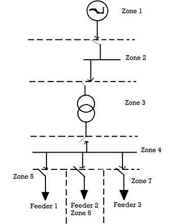
Following six categories of protection zones are possible in a system; we apply here a concept of selective coordination.
- Generators and generator–transformer units
- Transformers
- Buses
- Lines (transmission, sub-transmission, and distribution)
- Utilization equipment (motors, static loads, or other)
- Capacitor or reactor banks (when separately protected).
Primary Protection
The primary protection scheme ensures fast and selective clearing of any fault within the boundaries of the circuit element, that the zone is required to protect. Primary Protection as a rule is provided for each section of an electrical installation. However, the primary protection may fail. The primary cause of failure of the Primary Protection system is enumerated below.
1. Current or voltage supply to the relay.
2. D.C. Tripping voltage supply
3. Protective relays
4. Tripping circuit
5. Circuit Breaker
Backup Protection
Back-up protection is the name given to a protection which backs the primary protection whenever the later fails in operation. The back-up protection by definition is slower than the primary protection system. The design of the back-up protection needs to be coordinated with the design of the primary protection and essentially it is the second line of defence after the primary protection system.
There must be able to discriminate the appropriate disconnecting device. The method of discriminating the faults are two types-
(a) Those which discriminate as to the location of fault.
(b) Type of fault Methods discriminate the type of faults are: The main aim is that the fault section of the system be isolated and in the minimum time.
i) Discrimination by time
Ii) Discrimination by current magnitude
Iii) Discrimination by time and direction
Iv) Discrimination by distance measurement
v) Time as an addition to current magnitude or distance discrimination
Vi) current balance discrimination
Vii) Power direction comparison discrimination
Viii) Phase comparison discrimination
Some of the commonly used components of the protective schemes are described here in brief. Those are
1. Relays
2. Circuit Breakers
3. Tripping and Auxiliary Supplies
4. Current Transformers
5. Voltage Transformers
(i) Relays- When any abnormal condition develop, the main function of a protective relay is to isolate the faulty section with the least interruption to the service by controlling or operation the circuit breaker. The relay may be designed to detect and to measure abnormal condition and close the contacts of the tripping circuit. The two categories of relay are most commonly used in protective relay a) Secondary indirect acting relays Example: Current, Voltage, Power, Impedance, Reactance and frequency whether minimum or maximum b) Secondary directing acting relay A group of over current and under voltage relays designed to operate immediately or with time lag. These are relays of the electromagnetic type which are built into circuit breaker operating mechanism.
(ii) Circuit Breakers- It is desirable to switch on or off the various circuits like transmission line, distributors generating plants under both normal and abnormal condition. This can be done by a switch and a fuse but the limitations are
1. It take some time to replace
2. It cannot successfully interrupt heavy fault current. So, we use CB. It can make or break a circuit either manually or automatically under all conditions (no load, full load and fault) i.e.
a) It can make or break a circuit manually or by remote under normal condition
b) Break a circuit automatically under fault condition
c) Make a circuit either manually or by remote under fault condition. For operation of CB a relay is necessary. A protective relay is a device that detects the faults and initiate the operation of the circuit breaker to isolate the defective element from the rest of the system. The electrical quantities which may change under fault condition are voltage, current, frequency and phase angle. Any changes in these quantities indicate presence of the fault. Tripping and other Auxiliary Supplies For protective relay and automatic control scheme in power system use two kinds of auxiliary supplies: DC and AC DC auxiliary power supply is provided from batteries which is maintained continuously charged.
The advantages of storage batteries are their high reliability and independent of power circuit conditions and of existence of fault. Usually, the voltage of the auxiliary supplies is maintained at 110 V Mainly the auxiliary supplies power to protective relays, automatic control and the circuit breakers tripping circuit. Separate buses may also be provided for supplying power to relays, CB and other indicating circuit such as alarm and warning signals. Relay with ac operative power from current transformer. In this scheme the relay has normally closed contacts. During normal operation the relay contacts continuously shut the circuit breakers trip coil and this keep the breaker closed. When abnormal condition is approached the relays operates to open its contacts this put the trip.
(iii) Current Transformer (CT)-High magnitude primary current are reduced to a value suitable for relay operation to a value suitable for relay operation with the help of current transformers (CTs). (Then CTs provide current in the relay which are proportional to those in primary.) The primary winding of the CTs is connected in series whit the load and carries the actual power system current (normal or fault). The secondary is connected to the measuring circuit or the relay. The working range of a protective CT extends over the full range between the ankle and the knee points and beyond. Whereas the measuring CT usually operate in region of ankle point. Measuring CTs require comparatively high accuracy over the range of 10% to 120% of rated. Grain oriented steels having high saturation level are used. As core materials for protective CTs and nickel iron alloys having low exciting ampere turn per unit length of the core use4d for measuring CTs. It is common practice to use 1A secondary rating CTs. The secondary of the bus bar primary CT is usually about 1500 secondary turn. When rated primary currents much in excess of 1500 A are encountered then the main bar CTs with rated secondary current of 5A and 10A along with auxiliary CTs of 5/1 or 10/1 respectively are used.
(iv) Voltage Transformers- It is not possible to connect the voltage coils of the protective device directly to the system in case of high voltage systems. So, it is necessary to step down the voltage, also to insulate the protective equipment from primary circuit. This is achieved by using a voltage transformer. Also known as potential transformer (PTs) which is similar to a power transformer. The voltage transformer is rated in terms of the maximum burden (VA) output it delivers without exceeding specified limits of errors. Whereas the power transformer is rated by the secondary output it delivers without exceeding a specified temperature rise. The output of PTs is usually limited to a few hundred-volt amperes and the secondary voltage is usually 110V between phases. Ideally a VT should produce a secondary voltage exactly proportion al to the primary voltage and exactly in phase opposition. This cannot Power System Protection 16 obviously be achieved in practice owing to the voltage drops in the primary and secondary coil due to the magnitude and power factor of the secondary burden. Thus, ratio errors and phase angle errors are introduced. There are two types of Voltage devices a) The conventional wound type voltage transformers up to (132kV) b) Capacitor Voltage Transformer (>132 kV) When Appreciable current flows in the burden both ratio and phase are introduced because of the load current flowing through the capacitor C1. The voltage drops on load due to reluctance of the capacitors can be compensated by inserting an inductance reactance in series with the load.
a) Sequence Impedance
Like the symmetrical components for the current, voltage and power, the impedances are also composed of symmetrical components known as the sequence impedances. These can be defined as follows: The positive sequence impedance of equipment is the impedance offered by the equipment to the flow of positive sequence impedance. Similarly, the negative and zero sequence impedance of the equipment is the impedance offered by the equipment to the flow of corresponding sequence currents.
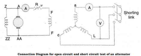
Measurement of positive sequence impedance: The positive sequence impedance depends upon the working of the machine, i.e., whether it is working under sub transient, transient or steady state condition. The impedance measured under steady state is known as synchronous impedance and is measured by the well-known open circuit and short circuit test. The impedance is defined as
Synchronous impedance in p.u

Method of test for synchronous Impedance: The machine here is run at a proper direction with the help of a prime mover. The shorting link switch is kept in off position to perform open circuit test and noted the readings of the voltmeter by varying the field current. Similarly, the short circuit test is done by putting the shorting switch on and noting the readings of armature current with the variation of the field current.
Measurement of Negative sequence Reactance: It is the impedance offered to the flow of negative sequence current.
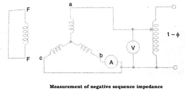
The machine here is driven at rated speed, and a reduced voltage is applied till the rated current flows in the armature. When there is a flow of negative sequence current there may be a possibility of hunting which would cause the pointer to deflect. This allows the mean reading to be taken. The negative sequence impedance is given by

Where V is the voltmeter and I is the ammeter reading.
Measurement of zero sequence impedance: Zero sequence impedance is the impedance offered by the machine to the flow of zero sequence current. This impedance depends on the distribution of the windings on the factors like pitch and breadth factors. The value is much smaller as compared to zero and negative sequences.
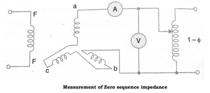
The machine is at standstill and a reduced voltage is applied. The zero-sequence impedance is-

b) Fault Calculations
The faults in a power system can be classified as: 1. Shunt Faults 2. Series Faults Shunt type of faults involve power conductors or conductors-to-ground or short circuit between conductors. When the circuits are controlled by fuses and in which Power System Protection 31 one or two phases of the circuit gets opened while the other phase is closed, such type of faults is known as series faults. Shunt faults may be classified as (i) Line-to ground fault; (ii) Line-to-line fault; (iii) Double line to ground fault; and (iv) 3-phase fault. Of these, the first three are unsymmetrical faults as the symmetry is distributed over one or two phases while the 3-phase fault is a balanced fault. Series faults are classified as: (i) one open conductor; and (ii) two open conductors. These faults disturb the symmetry in one or two phases and are unbalanced faults. We are mainly concerned with symmetrical faults
Voltage of the neutral- The potential of the neutral when it is grounded through some impedance is not equal to the ground potential under unbalanced operation. The potential of the neutral is given as, where Zn is the neutral grounding impedance and the In is the neutral current. Here negative sign is given as the current flows from the ground to the neutral of the system and the potential of the neutral is lower than the ground.


Since the positive and negative sequence currents are absent through the neutral are absent, hence the drops due to these currents are also zero. Also, for the balanced set of currents or voltages, the neutral is at the ground potential. Therefore, for positive and negative sequence networks, neutral of the system will be taken as reference.
Reference of Voltages- The phase voltages at any point in a grounded system and their zero sequence components of voltage will be referred to the ground at that point. The positive and negative sequence components of voltage are referred to neutral. Therefore, the voltage to ground and voltage to neutral is use alternatively but for the zero-sequence system it is important to distinguish between the two terms.
The system to be analyzed is given below. If there is a line-to-ground fault at phase a, the boundary conditions are-

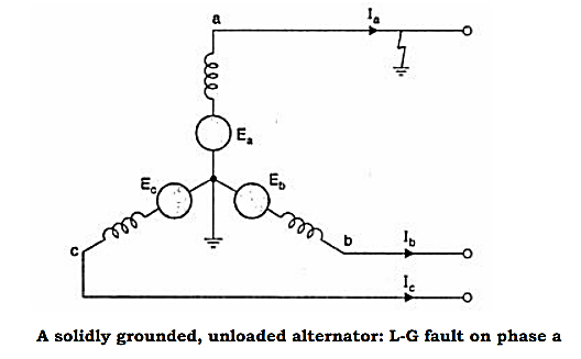
The sequence network equations are-


The solution of these six equations will give all the six sequence components of voltage and current. From the sequence current equations


Substituting the values of Ib & Ic in the above equations-

Similarly, according to symmetrical component of voltage-

Substituting the values of sequence voltages from the sequence network equation,

Since, 
The above equation becomes-


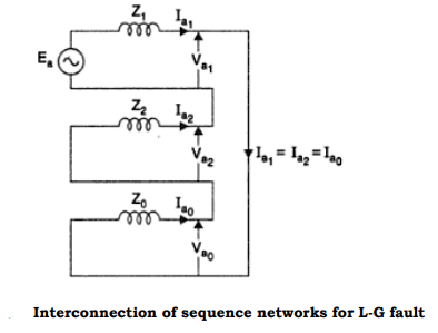
From the above equation it is evident that to simulate an L-G fault all the three sequence networks are required, and all these sequence networks are to be connected in series, as the sequence currents are equal in magnitude and phase. The interconnection is shown in the figure below-
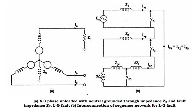
When the fault impedance and the neutral impedance are included, the analysis of the single line to ground fault can be analyzed as follows. The boundary conditions are-


From the above equations, the sequence components can be derived as


The fault diagram and the interconnection is given below
The faults in the power system are analyzed by making use of Thevenin’s theorem about the point of fault location. The theorem is important as it can determine the changes in currents and voltages of a linear network when additional impedance is added between two nodes of the network. To determine the distribution in current and voltage in the system, the distribution in each of the sequence networks must be determined. The Thevenin’s equivalents of positive, negative and zero sequence networks are equivalent to those of the networks for a single generator. Considering the system given below, it is needed to find the Thevenin equivalent network for determining the positive, negative and zero sequence networks about the point P.
The Thevenin equivalent of the positive sequence network is obtained from the positive sequence network. The Thevenin equivalent voltage source is the prefault voltage at the fault point P and the equivalent impedance Z1eq is the impedance as seen between the fault point and the zero potential bus shorting the voltage sources. Similarly, the Thevenin equivalent negative and zero sequence networks are obtained from the negative and zero sequence networks respectively. Since the system is balanced, no negative or zero sequence currents are flowing before the fault occurs. Hence the prefault voltage of both negative and zero sequence are equal to zero. The Thevenin Equivalent Network can be given as below-
Bus zone protection includes the bus itself as well as circuit breakers, disconnecting switches, instrument transformers and bus sectionalizing reactors. These faults occur rarely in the system but the provision of bus bar protection is necessary at the large and important station as the bus zone fault would result in interruption of high amount of power.
Bus Zone Faults The faults in the bus zone can be divided as follows: (i) Failure of circuit breaker to interrupt fault current or failure to clear under through fault conditions. (ii) Insulation failure due to material deterioration. (iii) Flashover causes by prolonged and excessive over voltages. (iv) Errors in the operation and maintenance of switchgears. (v) Foreign objects accidentally falling across bus bars. Bus Backup Protection When no separate protection is provided for the bus bars but there is a provision of distance protection, so any fault that is occurring at the bus zone protection would come under the zone 2 protection of the distance relay where it covers the bus bar and the next line also. This is satisfactory for the small switchgear case but not in the case of prime installations. Therefore, a separate bus zone protection may be provided for the same. Differential Scheme of Bus Bar Protection It is based on the simple circulating current principle that during the normal condition or external fault condition, the incoming current must be equal to the leaving current. Since the bus in a power system acts as a node in an electrical circuit, if the summation of currents is not equal to zero, it means that there is a short circuit due to ground fault or phase to phase fault. The differential scheme can be given as below, whose CT ratio are given according to the highest current that is flowing in the feeder circuits.
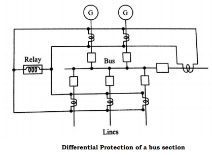
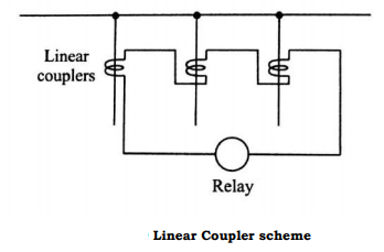
Since the CTs used here are of the same ratio, when there is a through fault condition, the magnetic conditions of the iron cored CTs would result in false operation due to saturation. Even with biasing of the relay, the improvement is not satisfactory. An improvement can be done by the use of non-iron cored CT also known as linear coupler to overcome the difficulties of iron cored CTs. In this the secondary voltage is proportional to the primary current. So, when there is an external fault, the addition of the voltages won’t result to zero since the current is still balanced, but when there is an internal fault there is an unbalance in current and hence results to some voltage in the linear coupler scheme.
Frame Leakage Protection It is possible to design a station so that the faults which develop are mostly earth faults, by providing earthed metal barrier surrounding each conductor in the bus structure. With this arrangement every fault that might occur must involve a connection between the conductor and an earthed metal part. The figure below shows the metal supporting structure also known as a fault bus earthed through a CT. Sometimes, the structure is earthed by the means of impedance connected in the neutral.
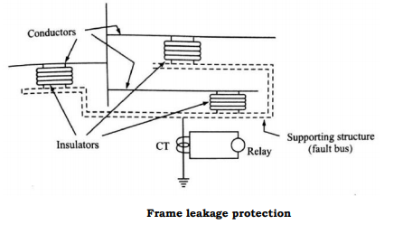
In the resistance earthed neutral, the advantage is that besides limiting the value of current it is also used to protect certain part of the generator or transformer windings which are connected in the feeder circuits. The earth fault current for protecting x% of the winding is given as This must be also the primary fault setting of the differential protection IS for minimum operating current.

This must be also the primary fault setting of the differential protection IS for minimum operating current.

Or % winding unprotected is-

References:
1. Power System Protection and Switchgear – B. Ravindranath & M. Chander–New Age International Publishers (Second Edition)
2. Electrical Power System - C.L. Wadhwa New Age International Publishers. (Sixth Edition).
3. Power System Engineering - M.L. Soni, P.V. Gupta, U.S. Bhatnagar, A. Chakrabarti, Dhanpat Rai & Co. (P) Ltd.
4. Switchgear and Protection – Sunil S Rao, Khanna Publishers, New Delhi.