Unit - 4
Switchgears
Auto reclosing is a phenomenon in which the breaker tries to reconnect the line between two points with the delay or without delay at the time of the fault.
It is well realized that the transient faults which are most frequent in occurrence do no permanent damage to the system as they are transitory in nature. These faults disappear if the line is disconnected from the system momentarily in order to allow the are to extinguish. After The arc path has become sufficiently deionized, the line can be reclosed to restore normal service. The type of fault could be a flashover across an insulator. Reclosing could also achieve the same thing with semi-permanent faults but with a delayed action, e.g., a small tree branch falling on the line, in which case the cause of the fault would not be removed by the immediate tripping of the circuit breaker.
Types of Auto Reclosing Circuit Breaker can be broadly classified in two categories: Medium voltage auto-reclose where continuity of supply is the principal aim. High voltage auto-reclose where the main considerations are of stability and synchronizing. Medium Voltage Auto-Reclose: The obvious advantages are continuous supply except for short duration when tripping and reclosure operations are being performed, this renders the substation unattended. The success of rapid reclosure to a large extent depends on the speed of operation of the protections. This is so because high speed protection decreases the amount of damage incurred and thus increases the probability of successful operation of reclosing, consequently it renders the system less vulnerable to any fault which may occur later.
A circuit breaker is a device that switches on and switches off electric circuits during normal as well as abnormal operating conditions. During the making or breaking of the switching contacts, there is a transition stage of arcing between the contacts. The study of this phenomenon is of great importance for understanding the design and operational characteristics of circuit breakers.
When a live circuit is interrupted, an arc is invariably formed between the parting contacts, the intensity and magnitude of which would depend upon the quantum and the quality (p.f.) of the current being interrupted. The arc, due to its excessive heat, under high pressure or vacuum (the medium in the interrupter is maintained thus), forms a plasma in the medium which causes decomposition of the insulating and the quenching medium to a few gases and vapors. The gases so formed then ionize into electrons and protons, which are charged particles conducting in nature, and make the arc conducting as well. How to disperse the heat of the arc plasma quickly for a successful interruption of the circuit is the theory of arc extinction. The main problem of circuit breaking arises out of formation of the arc and its prolonged extinction, which may delay the circuit interruption and lead to a restrike of the arc plasma after a current zero. The basic concept of a circuit breaking thus leads to the quickest extinction of the arc plasma.
Physics of arc phenomena
Discharge in ac circuit breakers, generally in the form of an arc, occurs in the following ways:
1. When the contacts are being separated, arcing is possible even when the circuit emf is considerably below the minimum cold electrode breakdown voltage, because of the large local increase in voltage due to the circuit self-inductance.
2. In an ac circuit breaker, the arc is extinguished every time the current passes through zero and can restrike only if the transient recovery voltage across the electrodes already separated and continuing to separate reaches a sufficiently high value known as the breakdown voltage.
The arc phenomenon depends upon
● The nature and pressure P of the medium
● The external ionizing and deionizing agents present
● The voltage V across the electrodes and its variation with time
● The nature, shape, and separation of electrodes
● The nature and shape of the vessel and its position in relation to the electrodes
An ideal gas is a pure dielectric because it consists of molecules which are electrically neutral. It can be made to conduct only when some means are employed to create free electrons and ions in the gas.
When the gas temperature increases significantly, the molecules start to break down at the most severe collisions and dissociate into their atoms. Energies of 9.7 eV and 5.1 eV, respectively, are needed to dissociate an N2 and an O2 molecule. At higher temperatures, some molecules and atoms are deprived of an electron and the hot gas called plasma becomes a conductor.
Arc Interruption Theory
In circuit breakers, the modes of arc interruption are high-resistance interruption and low- resistance or current zero interruption.
High-Resistance Interruption
The arc is controlled in such a way that its effective resistance increases with time, resulting in a decrease in current until it cannot be maintained. The arc resistance can be increased by lengthening, cooling, and splitting the arc.
Low-Resistance or Current Zero Interruption
In an alternating current, every time the current passes through zero, the arc extinguishes for a brief moment and again restrikes with the rising current. The reestablishment or interruption of the arc is an energy balance process.
If the energy input to the arc, subsequent to the current zero, continues to increase, the arc restrikes; if not, the circuit is interrupted.
(i) Characteristics of Rate of Rise of Restriking Voltage: The important Characteristics of Rate of Rise of Restriking Voltage which affect the circuit breaker performance are: amplitude factor, rate of rise of restriking voltage (RRRV).
(ii) Circuit Breaker Rating: The ratings of a circuit breaker refer to the characteristic values that define the working conditions for which the circuit breaker is designed and built. Circuit breakers must be capable of carrying continuously the full load current, without excessive temperature rise, and should be capable of withstanding the electrodynamic forces.
(iii) Current Chopping: When interrupting small inductive currents such as transformer excitation currents, circuit breakers tend to clear before the natural current zero is reached. This is because the low-current ionized conducting path may become prematurely unstable, forcing the low arc current to zero along a very steep wave front. This phenomenon is known as current chopping.
(iv) Duties of circuit breaker diagram: Under different circumstances Duties of circuit breaker diagram may be subjected to widely varying stresses. The current varies from a few amperes due to no-load current of a transformer up to the heaviest short-circuit currents, which may amount to a hundred kilo amperes.
(v) Recovery Voltage: While closing or opening the circuit breaker, the circuit constants play an important role. It was noticed in practice a circuit breaker that would operate satisfactorily at one point on a system may not do so at another, showing that the circuit conditions have some influence on the circuit breaker behavior.
(vi) Restriking Voltage Transient: Electrically a power system is an oscillatory network so that it is logical to expect that the interruption of fault current will give rise to a transient, whose frequency depends on the Circuit Constant of the circuit. It has been pointed out earlier that this transient voltage is referred to as Restriking Voltage Transient.
(vii) Interaction of Circuit Breaker: The circuit breaker performance can well be seen from the interaction between the breaker and the circuit. It is convenient to regard the short-circuit current i in the period around current zero as composed of two parts: the arc current ia and the transient current ic flowing in the capacitive part of the circuit which determines the restriking voltage. The voltage across the circuit breaker ea is related to ia by the dynamic characteristics of the arc and also to ic by the inherent transient response of the external circuit, while at any instant before or after zero i = ic + ia.
Electrically a power system is an oscillatory network so that it is logical to expect that the interruption of fault current will give rise to a transient whose frequency depends on the constants of the circuit.
Let us consider a simple circuit, having a circuit breaker CB, as illustrated in figure (a) and that a short circuit occurs on the feeder close to the bus-bars. The equivalent circuit is shown in figure (b). Let L be the inductance per phase of the system up to the fault point, R be the resistance per phase of the system up to the fault point and C be the capacitance to earth of circuit-breaker porcelain bushing.
Consider the opening of a circuit breaker under fault conditions shown in simplified form in figure (b). Before current interruption, the capacitance C is short circuited by the fault and the short-circuit current through the breaker is limited by resistance R and inductance L of the system. If R is negligible compared to L, the short-circuit current i will lag behind the system voltage v by 90°, as illustrated in figure (c).
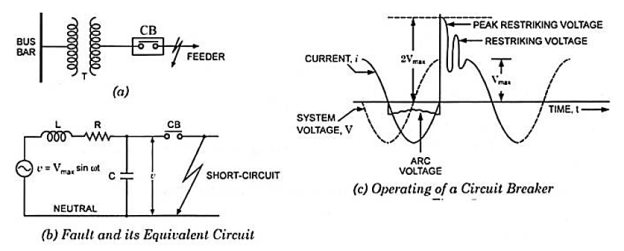
With the contacts opened and the arc broken, current i is diverted through capacitance C so that the voltage v, which has so far been effective only across the inductance L, is suddenly applied to the inductance L and capacitance C in series which form an oscillatory circuit, having a natural frequency.

The initial charging current surge tends to carry the voltage across the capacitor, and therefore across the circuit breaker contacts to double its equilibrium value i.e., 2 Vmax; this is the re-striking voltage transient which tends to re-establish the arc in the circuit breaker. These frequencies are of the order of 10 Hz to 10 kHz depending upon the values of L and C. The actual power system is composed of distributed capacitances and inductances. The circuit configuration is also complex. The re-striking voltage transient for such circuits can have several component frequencies ranging from a few Hz to several kHz
The important characteristics of re-striking voltage which affect the performance of the circuit breaker are:
(i) Amplitude factor and
(ii) Rate of rise of re-striking voltage, abbreviated as RRRV.
(i) Amplitude Factor:
The amplitude factor is defined as the ratio of the peak of transient voltage to the peak system frequency voltage.
(ii) Rate of Rise of Re-Striking Voltage (RRRV):
It is the rate of rise of re-striking voltage and is expressed in kV/µs. It may be defined as the slope of the steepest tangent to the re-striking voltage curve. For a re-striking voltage having a single frequency transient component the RRRV is obtained by dividing the maximum amplitude of the oscillation by the duration of the first half wave. Higher values of natural frequencies can be related with higher rates of rise of re-striking voltage.
It is clear that other things being equal, the duty of circuit breaker is much more severe when employed in a network of higher natural frequency than on a network of low natural frequency. This is because the average RRRV is much greater in the former case. In the latter case the voltage across the circuit breaker contacts rises slowly thereby giving longer time for building up of the dielectric strength.
Expression for RRRV:
It is given as –
 and
and 
RRV will be maximum when sin  or
or 
Hence maximum value of RRRV, RRR
Further, the peak restriking voltage occurs when v is maximum i.e., when

The circuit breaker performance can well be seen from the interaction between the breaker and the circuit. It is convenient to regard the short-circuit current i in the period around current zero as composed of two parts: the arc current ia and the transient current ic flowing in the capacitive part of the circuit which determines the restriking voltage. The voltage across the circuit breaker ea is related to ia by the dynamic characteristics of the arc and also to ic by the inherent transient response of the external circuit, while at any instant before or after zero i = ic + ia. Figure below shows in schematic form how the current across the capacitance C aids interruption by lowering the current immediately before zero.
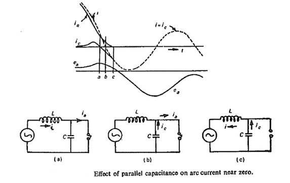
If e is the supply voltage in the circuit then the equation of the circuit can be written as e = L di/dt + ea. Considering the events occurring from the time when ea begins to rise, this causes a diversion of current into the shunt capacitance C given by ic = C dea/dt. This current is positive and since ia = i – ic, it is obtained at the expense of the arc current which therefore starts to fall more rapidly than i. Now as the instant a is approached, the rate of fall of ia diminishes and at instant a, dea/dt = 0, ic=0, and ia = i (Fig. a). Immediately after this the capacitance C starts discharging giving negative ic, whereas i and ia are still positive, so that the arc is supplied from both the source and the capacitance, obviously during this period ia is greater than i. At instant b when i reaches zero, Fig. (b), the arc is supplied only by the capacitance ia = ic and i=0. After this instant the current i reverses, and the difference constitutes ia. In the negative direction i rises at a faster rate than ic until at instant c, i = ic and the arc is extinguished, i.e. ia= 0 (Fig. (c).
The interaction between arc and circuit can be calculated around current zero, if the time constant τ and rate of power dissipation of the arc, as well as the initial conditions of the interaction interval are known. These values can be measured and put into a mathematical arc model, which has to be combined with the differential equation of the circuit. The voltage required to maintain an arc at a given current may be much less when the current has been decreasing rapidly than in the static case. The heat balance of the arc, and hence its temperature and conductivity, is determined by P = eaia (the electrical power input) and P0 (the rate of heat removal by the blast). If R is taken as the instantaneous value of the arc resistance and τ the thermal time constant, we obtain-

For successful clearance R continues to increase after current zero. With the aid of computer, it is possible to calculate the curves of current and voltage around current zero and to decide whether or not residual conductance and thermal reignition of the arc path occurs.
It is the phenomenon of current interruption before the natural current zero is reached. Current chopping mainly occurs in air-blast circuit breakers because they retain the same extinguishing power irrespective of the magnitude of the current to be interrupted. When breaking low currents (e.g., transformer magnetizing current) with such breakers, the powerful de-ionizing effect of air-blast causes the current to fall abruptly to zero well before the natural current zero is reached. This phenomenon is known as current chopping and results in the production of high voltage transient across the contacts of the circuit breaker as discussed below:
In the figure given below- (i). Suppose the arc current is i when it is chopped down to zero value as shown by point a in figure (ii). As the chop occurs at current i, therefore, the energy stored in inductance is L i2 /2. This energy will be transferred to the capacitance C, charging the latter to a prospective voltage e given by:

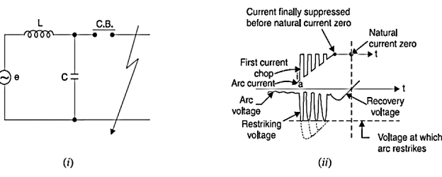
The prospective voltage e is very high as compared to the dielectric strength gained by the gap so that the breaker restrike. As the de-ionizing force is still in action, therefore, chop occurs again but the arc current this time is smaller than the previous case. This induces a lower prospective voltage to re-ignite the arc. In fact, several chops may occur until a low enough current is interrupted which produces insufficient induced voltage to re-strike across the breaker gap. Consequently, the final interruption of current takes place. Excessive voltage surges due to current chopping are prevented by shunting the contacts of the breaker with a resistor (resistance switching) such that re ignition is unlikely to occur.
A circuit breaker can make or break a circuit either manually or automatically under all conditions viz., no-load, full-load and short-circuit conditions. This characteristic of the Circuit Breakers Definition has made it a very useful equipment for switching and protection of various parts of the power system.
A Circuit Breakers Definition is a piece of equipment which can-
- Make or break a circuit either manually or by remote control under normal conditions
- Break a circuit automatically under fault conditions
- Make a circuit either manually or by remote control under faith conditions
Thus, a circuit breaker incorporates manual (or remote control) as well as automatic control for switching functions. The latter control employs relays and operates only under fault conditions.
Operating principle:
A Circuit Breakers Definition essentially consists of fixed and moving contacts, called electrodes. Under normal operating conditions, these contacts remain closed and will not open automatically until and unless the system becomes faulty. Of course, the contacts can be opened manually or by remote control whenever desired. When a fault occurs on any part of the system, the trip coils of the circuit breaker get energised and the moving contacts are pulled apart by some mechanism, thus opening the circuit.
When the contacts of a circuit breaker are separated under fault conditions, an arc is struck between them. The current is thus able to continue until the discharge ceases. The production of arc not only delays the current interruption process but it also generates enormous heat which may cause damage to the system or to the circuit breaker itself. Therefore, the main problem in a Circuit Breakers Definition into extinguish the arc within the shortest possible time so that heat generated by it may not reach a dangerous value.
Arc Phenomenon:
When a short-circuit occurs, a heavy current flow through the contacts of the ‘circuit breaker, before they are opened by the protective system. At the instant when the contacts begin to separate, the contact area decreases rapidly and large fault current causes increased current density and hence rise in temperature. The heat produced in the medium between contacts (usually the medium is oil or air) is sufficient to ionise the air or vaporise and ionise the oil. The ionised air or vapour acts as conductor and an arc is struck between the contacts. The p.d. Between the contacts is quite small and is just sufficient to maintain the arc. The arc provides a low resistance path and consequently the current in the circuit remains uninterrupted so long as the arc persists.
During the arcing period, the current flowing between the contacts depends upon the arc resistance. The greater the arc resistance, the smaller the current that flows between the contacts. The arc resistance depends upon the following factors:
Degree of ionisation – the arc resistance increases with the decrease in the number of ionised particles between the contacts.
Length of the arc – the arc resistance increases with the length of the arc i.e., separation of contacts.
Cross-section of arc – the arc resistance increases with the decrease in area of X-section of the arc.
4.8.1 Types of Circuit Breakers-
(i) Air Blast Circuit Breaker-
It is not possible to produce a low resistance arc without a considerable gas pressure so that the only type available employs a high-pressure gas blast sweeping across the contact space. The gases which can be used are compressed air, nitrogen, carbon dioxide, hydrogen and freon. Now nitrogen is equivalent in circuit breaking properties to compressed air and therefore there is no advantage in using nitrogen. Carbon dioxide has the drawback of its being difficult to control owing to freezing at valves and other restricted passages. Tests have shown an increased breaking capacity by the use of hydrogen, but its cost and that of the ancillary apparatus are a serious objection. Freon has high dielectric strength and good extinguishing properties, but it is expensive and it is decomposed by the arc into acid forming elements. It follows from the above that compressed air is the accepted circuit-breaking medium for gas-blast circuit breakers.
All Air Blast Circuit Breaker follow the principle of separating their contacts in a flow of air established by the opening of a blast valve. The arc which is drawn is usually rapidly positioned centrally through a nozzle where it is kept to a fixed length and is subject to maximum scavenging by the air flow. Arrangements vary but can be grouped into three types as shown in figure below: (a) axial blast, (b) radial blast and (c) cross blast. Axial or radial blast seems to be favoured for the higher voltages although cross blast breakers particularly for voltages of about 15 KV and heavy current (up to 100 KA) have proved satisfactory and require less air than would an axial-blast breaker at these high currents.
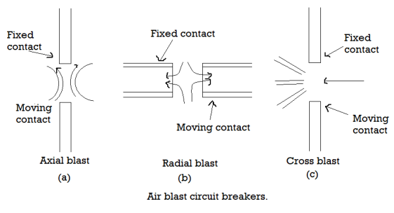
It is well recognized that the main structural advantage of the axial-blast circuit breaker over the cross blast is its easier adaptability to high voltage insulation particularly for outdoor applications. This is because the interrupting chambers can be fully enclosed in porcelain tubes. The axial blast type of circuit breaker thus is ideal for high and super voltage application and outdoors where dust and corrosive fumes are encountered. In the indoor high power medium voltage class of circuit breakers currents of 2000-4000A are common, requiring special multifinger contacts in order to keep the temperature low enough to prevent damaging oxidation. A multiple interruption by air blast can be arranged for very high voltages and exerting a joint radial and axial cooling by direct air convection. In order to secure high air velocities in Air Blast Circuit Breaker it is imperative to provide for relatively short wide passages for the air flow between pressure reservoir and arc. If the necessary volume of air is available near the arc, velocities exceeding that of sound may be attained at the critical instant of extinction.
Working Principle of Air Blast Circuit Breaker:
Gas blast interruption is dependent on turbulent cooling, and is therefore influenced by aerodynamic configuration, including nozzles, gas flow passages and mass flow. Compressed air is an excellent insulant, and is forced on the arc at the instant of contact separation. The compressed air the arc through the nozzle, which helps exhaust the hot gas and the arcing products to the atmosphere. In this way the interrupter of an Air Blast Circuit Breaker performs its operating cycle for its ideal characteristics. Extinction occurs at the first current zero when the flow of compressed air increases rapidly to establish the dielectric strength between the electrodes to withstand restriking voltage. The growth of dielectric strength is rapid and pressure of air is so high that the final gap caused by interposition of insulating layer of air between the contacts need only be small, thus reducing the size of the device. The energy supplied for arc extinction is obtained from high pressure air and is independent of the current to be interrupted.
Construction of Air Blast Circuit Breaker
The figure below shows the essential elements of an air-blast interrupter. With the breaker closed, load current is carried by heavy copper main contacts. Following the instruction to trip, the air blast at about 2 MN/m2 (1MN/m2=145 psi=9.9 atmospheres) is turned on by the opening of a valve and the moving contacts set in rapid motion by the action of compressed air on a piston. As the contacts part, an arc is either drawn between special arcing contacts or transferred to them by the blast. The maximum separation of the contacts is in the region 10-20 mm and is commonly attained in 3 ms.
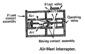
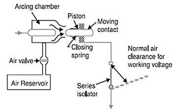
In actual Air Blast Circuit Breaker local air storage may be at earth potential and air supplied to the interrupters through insulating pipes or it may be mounted at the level of the interrupters at line potential and the air fed through insulating pipes. The blast valve may also be in one of many positions as given below:
- Receiver on the ground and blast valve at low level. Here the blast pipe must be filled before the interrupters are supplied with air.
- Receiver on the ground and blast valve at high level. This reduces the amount of air wasted but requires an insulated drive to the blast
- Live receiver and blast valve. Shorter opening times are possible as the air is stored near the interrupter units.
(ii) Air Break Circuit Breaker
The arc interruption process of Air Break Circuit Breaker is based on the natural deionization of gases by a cooling action. The arc is resilient and can be stretched, and has resistance which can be increased both by length and confinement. Hence the increase of arc resistance is so high that the short-circuit current drops and the current and voltage are brought into phase. Reducing the phase difference between the system voltage and the short-circuit current assures that when the arc current is interrupted at its zero value, the recovery voltage has a very low value at this instant. Restriking voltage is thus reduced to a much smaller value and is not allowed to reach two-times the value of the system peak voltage, a phenomenon that occurs in most cases, when arc current is interrupted at low power factor by means of other conventional circuit breakers. The energy dissipated in the arc is however high and this limits the application of high-resistance interruption to low and medium power a.e. circuit breakers; it is also used for low and medium power d.c. Circuit breakers.
Construction of Air Break Circuit Braker
The breaker generally, consists of three single-pole units linked together by an insulated cross-bar, and operated by one or more mechanisms according to the current rating. The complete assembly, including the mechanism, is mounted on a panel of insulating material, with arc-resisting barriers on both sides of each pole.
Pole Unit: Each pole is made up on an independent insulating moulded piece on which are mounted main contacts, arcing contacts, arc chute, direct instantaneous releases and current transformers for operating thermal release.
Contacts: As a matter of fact there are many types of contacts used in different designs and it is beyond the scope of this book to describe all of them. However, one type will be discussed here.
(a) Main contacts: These carry the rated continuous current and consist of the moving contact assembly and the fixed contact assembly.
Moving contact assembly: These are solid copper spring-loaded rollers ringed with silver. The floating rollers turn around their axles by a few degrees each time the breaker is closed, assuring thereby a wiping action. The rotating action assures uniform wear and tear of the entire moving contact surface instead of a restricted part of the surface. The life of the moving roller contacts is therefore longer than standard leaf contacts.
Fixed contact assembly: These comprise two levelled copper, contact bars (line and load side) with silver pads at contact faces. The two fixed contacts are shunted by rollers. This arrangement assures an excellent durability of contacts and a minimum temperature rise. The design of the fixed contact is such that there is no other path than the main contacts for carrying the continuous current between line and load terminals.
(b) Arcing contacts: Arcing contacts have to undergo the effect of arcing and they open after and close before main contacts. Their shape is such that electrodynamic blow-on forces are used to compensate repulsion forces resulting in increased contact pressure to avoid any beat phenomenon, whatever be the time-delay of tripping.
Arc Chutes: All arc chutes are made of an insulating arc-resisting material, and surround each pole unit. The dimensions of the chute depend on the number of arcing contacts. The chute is shaped like a funnel with restricted area at its lower part. At the top, the arc chute houses a grid of steel plates the function of which is to increase the speed of rise of the arc into the chute by magnetic action. It also splits the arc and results in increasing the arcing voltage and deionizing the plasma by a strong cooling action.
Operating Mechanism
The mechanism for a.c. Circuit breakers is usually designed for manual operation, but electrical operation such as electrical spring charged mechanism can be provided for remote control. The duties expected of a modern apparatus are: trip-free operation, independent opening, lockout feature preventing closing and, in the event of stored-energy operating-mechanism, independent closing.
Most types of operating mechanism have as their basis either the lever-and-toggle or the cam-and-roller system. The moving contact arm and its associated members are made as light as practicable in order to achieve the high breaking speed. Powerful springs are used to give rapid acceleration. Mechanisms are invariably of the trip-free type, and in some designs for manual closing there is included a device that causes immediate tripping if any reversal occurs in the direction of motion of the operating handle.
(iii) Oil Circuit Breaker
Oil Circuit Breaker are extensively employed in our power systems. In these the properties of the arc are employed for arc extinction. Thus, by using arc energy to crack the oil molecules, hydrogen gas may be generated which can be used to sweep, cool and compress the arc plasma and so deionize it in a self-extinguishing, process.
Earlier it was thought that the oil acted as an insulator when the breaker was closed and then it flowed into the arc gap when the contacts separated and smothered the arc. But later on, experiments showed that it would be quite impossible in the very short time of 1/2 to 1/4 cycle available for oil to flow and smother the arc.
Types of Oil Circuit Breakers
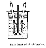
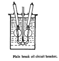
(a) Plain Break Oil Circuit Breaker- In this type the arc is confined only within the oil tank. Deionization of arc is due entirely to turbulence and increase of pressure. For successful interruption, a comparatively long arc-length is essential so that the turbulence in the oil caused by the pressures generated by the arc, may assist in quenching it. Because of the absence of effective control over the arc, the arcing times and the amount of energy released before interruption often vary over a wide range, thus making a large factor of safety necessary, in the design of the tank. The tank must be weathertight to keep moisture out. In case there is an air cushion above the oil, the hydrogen gas formed may pass through the oil to mix with the air, to form an explosive mixture unless sufficient pressure is maintained. The head of oil above the contacts must be large enough to prevent the escape of gas in the form of a column to the surface.
It is clear that if the contacts are separated at high speed, the arc length can be greatly increased because of the greater distance the moving contacts travel between current zeros at which interruption occurs. Welding of contacts may result on short-circuit interruption if the speed of contact movement is slow. By increasing the size of the tank, head of oil, length of break and insulation; it is possible to obtain breakers for higher voltage and larger interrupting capacities. However, circuit breakers of this type are not considered satisfactory above 11 KV and 250 MVA.
(b) Arc Control Circuit Breakers: The bulk oil circuit breakers generally employed in our power systems are of this type. In these the gases produced during arcing are confined to small volumes by the use of an insulating, rigid is chamber surrounding the contacts. Thus, higher pressures can be developed to force the oil and gas through or around the area to extinguish its These small, high pressure resistant chambers are known as are control pots or sometimes as explosion pots. Apart from their efficiency of are interruption these explosion pots have substantially brought down the risks of fire hazard. With the improvement in the design of the area control pots, great reductions have been seen affected both in arc duration and total break time.
(c) Minimum Oil Circuit Breaker: For higher voltages and higher breaking capacities large amounts of oil are required and the size of the bulk oil circuit breaker described above becomes inordinately large. For example, a 110 KV 3500 MVA breaker takes 8 to 12 thousand kg of oil, while a breaker of the same rating qut for 220KV takes 50 thousand kg of oil. The minimum oil circuit breaker uses solid materials for insulating purposes and uses just enough oil for arc quenching. The interrupting device is enclosed in a tank of insulating material, the whole of which is at line voltage in normal operation. These are also known as live tank breakers as against dead tank breakers of the bulk oil type. The minimum oil circuit breakers may be of self-blast type, external blast type or a combination of the two.
Two types of venting are used in the design of their arcing chambers, viz. Axial venting and radial venting. In axial venting the gases sweep the arc in longitudinal direction while in radial venting the arc is blown in transverse direction. Axial venting has the advantage that it generates high pressures and also has high dielectric strength. Axial venting is mainly where low currents are to be interrupted at high voltages. Radial venting generates low pressures and also has low dielectric strength. It is mainly suitable for breaking heavy currents at low voltages. At times a combination of both is used so that arcing chamber is equally efficient at low as well as at high currents. These arcing chambers however suffer from the disadvantage that at very low currents, called critical current, they have a long arcing period. These critical currents generally lie between 10 to 100A.
Arc chambers used in minimum oil circuit breaker;
a) simple acing chamber called explosion chamber;
b) axial venting arcing chamber.
(iv) Vacuum Circuit Breaker
A vacuum circuit breaker is such kind of circuit breaker where the arc quenching takes place in vacuum. The technology is suitable for mainly medium voltage application. For higher voltage vacuum technology has been developed but not commercially viable. The operation of opening and closing of current carrying contacts and associated arc interruption take place in a vacuum chamber in the breaker which is called vacuum interrupter. The vacuum interrupter consists of a steel arc chamber in the centre symmetrically arranged ceramic insulators. The vacuum pressure inside a vacuum interrupter is normally maintained at 10-6 bar. The material used for current carrying contacts plays an important role in the performance of the Vacuum circuit breaker. Cu-Cr is the most ideal material to make VCB.
Operation of VCB
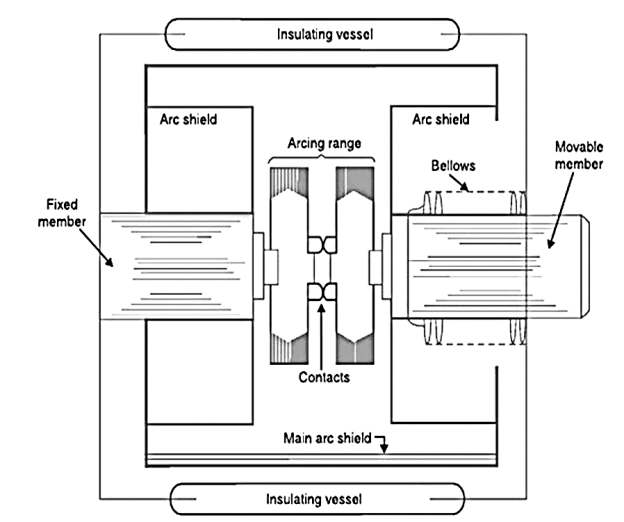
The main aim of any circuit breaker is to quench arc during current zero crossing, by establishing high dielectric strength in between the contacts so that reestablishment of arc after current zero becomes impossible. The dielectric strength of vacuum is eight times greater than that of air and four times greater than that of SF6 gas. This high dielectric strength makes it possible to quench a vacuum arc within very small contact gap. For short contact gap, low contact mass and no compression of medium the drive energy required in vacuum circuit breaker is minimum. When two face to face contact areas are just being separated to each other, they are not done so instantly. Instead, as the contact area on the contact face is being reduced and ultimately comes to a point and then they are finally de-touched. This happens in a fraction of micro second. At this instant of de-touching of contacts in a vacuum, the current through the contacts concentrated on that last contact point on the contact surface and makes a hot spot there. As the medium is vacuum, the metal on the contact surface gets easily vaporized due to that hot spot and create a conducting media for arc path. Therefore, the material constituting the arc is very small and thus a feeble arc is established even with high current interruption. The arc will be initiated and continues until the onset of next current zero. Th figure below shows the cross-section assembly of a VCB.

At current zero this vacuum arc is extinguished and the conducting metal vapor is recondensed on the contact surface. At this point, the contacts are already separated hence there is no question of re-vaporization of contact surface, for next cycle of current. That means, the arc cannot be re-established again. In this way vacuum circuit breaker prevents the reestablishment of arc by producing high dielectric strength in the contact gap after current zero. There are two types of arc shapes. For interrupting current up to 10 kA, the arc remains diffused and the form of vapor discharge and cover the entire contact surface. Above 10 kA the diffused arc is constricted considerably by its own magnetic field and the contracts.
(v) SF-6 Circuit Breaker
A circuit breaker in which the current carrying contacts operate in sulphur hexafluoride or SF6 gas is known as an SF6 circuit breaker. SF6 has excellent insulating property and it has a high electro-negativity. Therefore, it has high affinity of absorbing free electrons. Whenever a free electron collides with the SF6 gas molecule, it is absorbed by that gas molecule and forms a negative ion with the following processes.


These negative ions are much heavier than a free electron and therefore the over all mobility of the negatively charged particle in the medium is considerably reduced compared to other gases. As the mobility of charged particle is reduced, therefore the severity of arcing shall also be affected and reduced. Hence, for heavier and less mobile charged particles in SF6 gas, it acquires very high dielectric strength. Not only the gas has a good dielectric strength but also it has the unique property of fast recombination after the process of arcing is completed. The gas also has a very good heat transfer property. Due to its low gaseous viscosity (because of less molecular mobility) SF6 gas can efficiently transfer heat by convection. So due to its high dielectric strength and high cooling effect SF6 gas is approximately 100 times more effective arc quenching medium compared to air. Due to these unique properties of this gas, SF6 circuit breaker is used in complete range of medium voltage and high voltage electrical power system. These circuit breakers are available for the voltage ranges from 33KV to 800KV and even more.
Working of SF-6 Circuit
The working of SF6 CB of first generation was quite simple it is some extent similar to air blast circuit breaker. Here SF6 gas was compressed and stored in a high pressure reservoir. During operation of SF6 circuit breaker this highly compressed gas is released through the arc in breaker and collected to relatively low pressure reservoir and then it pumped back to the high pressure reservoir for re utilize.
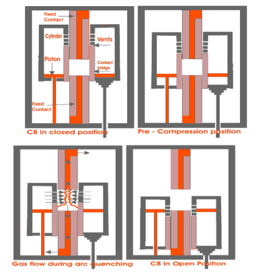
During opening of the breaker, the cylinder moves downwards against position of the fixed piston hence the volume inside the cylinder is reduced which produces compressed SF6 gas inside the cylinder. The cylinder has numbers of side vents which were blocked by upper fixed contact body during closed position. As the cylinder move further downwards, these vent openings cross the upper fixed contact, and become unblocked and then compressed SF6 gas inside the cylinder will come out through these vents in high speed towards the arc and passes through the axial hole of the both fixed contacts. The arc is quenched during this flow of SF6 gas.
During closing of the circuit breaker, the sliding cylinder moves upwards and as the position of piston remains at fixed height, the volume of the cylinder increases which introduces low pressure inside the cylinder compared to the surrounding. Due to this pressure difference SF6 gas from surrounding will try to enter in the cylinder. The higher-pressure gas will come through the axial hole of both fixed contact and enters into cylinder via vent and during this flow; the gas will quench the arc.
(vi) DC Circuit Breaker
It is well known that DC has no natural current zero. Therefore, the current either needs to reduced, by lengthening of the arc or cooling or by forced reduction of the current to zero. For lower voltage cases, a simple resistance and inductive coil connected across a switch forces the current to reduce to zero. Such a scheme is particularly being successful when the current magnitude is small. For higher voltage and current cases, a method that combines forced current reduction and grid control mechanism is applied.
Forced reduction of current zero: In this method an oscillatory LC network is utilized to let an oscillatory current flow in opposite direction to that of the direct current (DC). The moment the oscillatory current magnitude exceeds the DC value, the breaker current falls to zero temporarily. This helps in quenching the arc. The peak oscillatory current of the LC circuit should be more than the DC value through the breaker.
A normally open (NO) and a Normally Closed (NC) auxiliary breakers are utilized to discharge and charge the capacitor of the LC unit. The capacitor first is charged to line voltage through the L and R through the NC breaker. At the desired instant of main C.B opening, the capacitor discharges through the L when, the NO breaker becomes closed and NC becoming open. In this scheme, the value of C is so chosen that, the rise time constant of the line voltage is smaller than the charging time constant of C, which ensures that the voltage across the C is maintained for longer time. Similarly, the value of L is so chosen that, the rise time constant of the line current should be more than the changing time constant of the oscillatory current, which ensures that the oscillatory current reaches the load current quickly. Light duty DC Circuit Breaker have been in use since long. However, with the latest developments in HVDC transmission there would naturally be the necessity of the HVDC circuit breaker. The two major problems of HVDC circuit breaking are:
- The amount of energy to be dissipated during the short interval of breaking is very high as compared to the conventional a.c. Circuit breakers.
- The natural zero current does not occur as in the case of a.c. Circuit breakers.
Resistance switching and efficient cooling by forcing the liquid or air blast are used to dissipate the high amount of energy, whereas artificial means are provided to bring the current to zero.
4.8.2 Advantages of Circuit Breakers
- It protects from damage caused by flow of excessive current.
- It is are more reliable.
- It can be reset as it operates via a switch.
- It is very sensitive in operation
- It has the facility of frequent operation.
- High insulation facility
4.8.3 Testing of Circuit Breaker
Type tests are conducted for the purpose of proving the capabilities and confirming the rated characteristic of the circuit breaker. Such tests are conducted in the specially built testing laboratory. Type tests can be broadly classified as the mechanical performance test, thermal test, dielectric or insulating test, short circuit test for checking the making capacity, breaking capacity, short time rating current and operating duty.
Mechanical Test – It is mechanical ability type test involving the repeated opening and closing of the breaker. A circuit breaker must open and close at the correct speed and perform its designated duty and operation without mechanical failure.
Thermal Test – Thermal tests are carried out to check the thermal behavior of the circuit breakers. The breaker under test deal with the steady-state temperature rises due to the flow of its rated current through its pole in a rated condition. The temperature rise for rated current should not exceed 40° for current less than 800A normal current and 50° for normal value of current 800A and above.
Dielectric Test – These tests are performed to check power frequency and impulse voltage withstand capacity. Power frequency tests are kept on a new circuit breaker; the test voltage changes with a circuit breaker rated voltage.
The test voltage with a frequency between 15-100Hz is applied as follows. (1) between poles with circuit breaker closed (2) between pole and earth with circuit breaker open, and (3) across terminals with circuit breaker open.
In impulse tests impulse voltage of specified magnitude is applied to the breaker. For outdoor circuit dry and wet tests are conducted.
Short -Circuit Test – Circuit breakers are subjected to sudden short-circuits in short-circuit test laboratories, and oscillograms are taken to know the behavior of the circuit breakers at the time of switching in, during contact breaking and after the arc extinction.
The oscillograms are studied with particular reference to the making and breaking currents, both symmetrical and asymmetrical restriking voltages, and switchgear is sometimes tested at rated conditions.
References:
1. Power System Protection and Switchgear – B.Ravindranath & M.Chander–New Age International Publishers (Second Edition)
2. Electrical Power System - C.L.Wadhwa New Age International Publishers. (Sixth Edition).
3. Power System Engineering - M.L.Soni, P.V.Gupta, U.S.Bhatnagar, A.Chakrabarti, Dhanpat Rai & Co. (P) Ltd.
4. Switchgear and Protection – Sunil S Rao, Khanna Publishers, New Delhi.