Unit - 4
Microwave Antennas
It is a radiating element which has the shape of a horn. It is a waveguide one end of which is flared out.
A waveguide, when excited at one end and open at the second end, radiates. However, radiation is poor and non-directive pattern results because of the mismatch between the waveguide and free space. The mouth of the waveguide is flared out to improve the radiation efficiency, directive pattern and directivity.
Types of horns:
Sectoral horn
Pyramidal horn
Conical horn.
Sectoral horn is of two types:
Sectoral H-plane horn
Sectoral E-plane horn.
These are shown in the figures below,
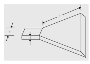
Fig 1 Sectoral H- plane horn
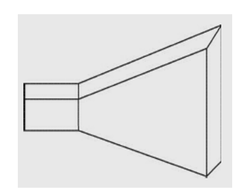
Sectoral E- plane horn
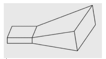
Fig 2 Pyramidal horn
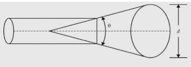
Fig 3 Conical horn
Sectoral horn is a horn in which flaring exists only in one direction. If flaring is along the direction of electric field, it is called sectoral E-plane horn. If flaring is along the direction of magnetic field, it is called sectoral H-plane horn. If flaring is along E and H, the horn is called pyramidal horn. It has the shape of a truncated pyramid. If the walls of a circular waveguide are flared out, a conical horn is obtained.
The horn parameters are described as shown in the figure below:
δ = path difference
l = axial length
d = aperture dimension
Ѳ = flare angle
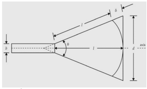
Fig 4 Horn parameters
Features:
Horn becomes small if the flare angle is small. Its radiation pattern is directive, wave front is spherical, mouth area is small and its directivity is small.
Flare angle is related to axial length.
If θ = 15°, when l/λ = 50, the beam width is 23° and directivity is 120. Directivity of pyramidal horn is more as the flare is in more than one direction.
Its directivity is not as high as that of paraboloid.
It is used as radiator.
It is easy to use with the waveguide.
It is used as primary antenna for paraboloid. The gain of the conical antenna is optimum for a given slant length of flare, l and

Here, d = diameter of the aperture.
The directivity of a loss-less horn antenna is its gain and it is given by

Here, Ae is effective aperture, in sq. m
Aa is actual area or physical area, in sq. m
ηa is aperture efficiency
λ is operating wavelength, in m.
In the case of rectangular horn Aa = dE dH
Here, dE is aperture size in E-plane dH is aperture size in H-plane
The rectangular horn is a pyramidal horn.
In the case of conical horn Aa = πd
Here, d is aperture diameter.
If aperture efficiency is about 0.6, D ≈ 7.5 Aa/λ.
Key takeaway
Horns are used at microwave frequencies where moderate gains are sufficient.
They are used as feed elements.
They are often used in laboratories for the measurement of different antenna parameters.
H- Plane Horns
The H-plane sectoral horn the geometry and the respective parameters shown in the figure below are used in the subsequent analysis. The two required dimensions for the construction of the horn are A and RH.
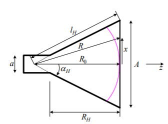
Fig 5 H-PLANE (X-Z) CUT OF AN H-PLANE SECTORAL HORN
l2H = R02 + (A/2)2
αH = arctan (A/2R0)
RH = (A-a) √ (IH/A) - (1/4)
The tangential field arriving at the input of the horn is composed of the transverse field components of the waveguide dominant mode TE10:
Ey(x) = Eo cos(πx/a) e-j gz
gz
Hx(x) = -Ey(x)/Zw
 is the wave impedance of the
  wave guide mode
 is the phase constant of the guided
  mode
mode
Here, 0 = √= 2 π/0, and 0 is the free-space wavelength. The field that is illuminating the aperture of the horn is essentially a spatially expanded version of the waveguide field. Note that the wave impedance of the flared waveguide (the horn) gradually approaches the intrinsic impedance of open space , as A (the H-plane width) increases. The complication in the analysis arises from the fact that the waves arriving at the horn aperture are not in phase due to the different path lengths from the horn apex. The aperture phase variation is given by e-j (R-Ro)
Since the aperture is not flared in the y-direction, the phase is uniform along y. We first approximate the path of the wave in the horn
R= √ =R0 √1+

The last approximation holds if x << R0, or A /2<< R0. Then, we can assume that
R-R0 

Eay(x)  E0 cos(πx/A) e-j
 x2/2
x2/2 0
0
The field at the aperture plane outside the aperture is assumed equal to zero. The field expression in above equation is substituted in the integral for IEy


The second integral has been already encountered. The first integral is cumbersome and the final result only is given below


And


C(x) and S(x) are Fresnel integrals, which are defined as


The far field can be calculated from IEy (,) as


The amplitude pattern of the H-plane sectoral horn is obtained as

Principal-plane patterns
E-plane ( = 90)

The second factor in above equation is dominant and it is identical to the second factor of the pattern of a slit of width b (along the y-axis).
H-plane ( = 0):

The H-plane pattern in terms of the I (,) integral is an approximation, which is a consequence of the phase approximation made in below equation. Accurate value for fH() is found by integrating numerically the field as

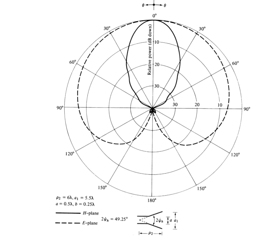
Fig 6 E- and H-Plane Pattern of H-Plane Sectoral Horn
Key takeaway
E-plane ( = 90)

H-plane ( = 0):

The pyramidal horn is probably the most popular antenna in the microwave frequency ranges (from 1 GHz up to 18 GHz). The feeding waveguide is flared in both directions, the E-plane and the H-plane. All results are combinations of the E-plane sectoral horn and the H-plane sectoral horn analyses. The field distribution at the aperture is approximated as

The E-plane principal pattern of the pyramidal horn is the same as the E-plane principal pattern of the E-plane sectoral horn. The same holds for the H-plane patterns of the pyramidal horn and the H-plane sectoral horn. The directivity of the pyramidal horn can be found by introducing the phase efficiency factors of both planes and the taper efficiency factor of the H-plane:


The gain of a horn is usually very close to its directivity because the radiation efficiency is very good (low losses). The directivity as calculated with (18.39) is very close to measurements. The above expression is a physical optics approximation, and it does not take into account only multiple diffractions, and the diffraction at the edges of the horn arising from reflections from the horn interior. That is why horns are often used as gain standards in antenna measurements. The optimal directivity of an E-plane horn is achieved at q =1The optimal directivity of an H-plane horn is achieved at t = 3 / 8, Hph =0.79. Thus, the optimal horn has a phase aperture efficiency of
Pph = Hph Eph =0.632
The total aperture efficiency includes the taper factor, too
Pph = Hph Eph =0.51
Therefore, the best achievable directivity for a rectangular waveguide horn is about half that of a uniform rectangular aperture.
Optimum horn design
Usually, the optimum (from the point of view of maximum gain) design of a horn is desired because it results in the shortest axial length for a given gain. The whole design can be actually reduced to
the solution of a single fourth-order equation. For a horn to be realizable, the following must be true:
RE = RH = RP
The figures below summarize the notations used in describing the horn’s geometry.
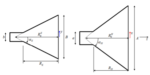
Fig 7 Geometry for Horn


The optimum-gain condition in the E-plane is substituted in above to produce

There is only one physically meaningful solution

Similarly, the maximum-gain condition for the H-plane of above equation

Since RE =RH must be fulfilled

Substituting in the expression for the horn’s gain

gives the relation between A, the gain G, and the aperture efficiency ap


The above equation is optimum pyramidal horn design equation.
Key takeaway
The above equation is optimum pyramidal horn design equation.

The gain of pyramidal horn antenna is given by
Gain = 4πAeA/ 2
2
Then for a conical horn the gain formula can be shown to be:
Gain = (πDeA/ )2
)2
Where;
A is the physical area of the aperture
d is the physical diameter of a conical horn aperture
λ is the wavelength
eA is the aperture efficiency and is a figure between 0 and 1
The horn antenna can operate very effectively. The flare of the horn antenna provides a smooth match between the waveguide and free space and its angle affects many properties including the gain and directivity.
Parabolic Reflectors are Microwave antennas. The frequency range used for the application of Parabolic reflector antennas is above 1MHz. These antennas are widely used for radio and wireless applications. The standard definition of a parabola is - Locus of a point, which moves in such a way that its distance from the fixed point (called focus) plus its distance from a straight line (called directrix) is constant.
The following figure shows the geometry of parabolic reflector. The point F is the focus (feed is given) and V is the vertex. The line joining F and V is the axis of symmetry. PQ are the reflected rays where L represents the line directrix on which the reflected points lie (to say that they are being collinear). Hence, as per the above definition, the distance between F and L lie constant with respect to the waves being focussed.
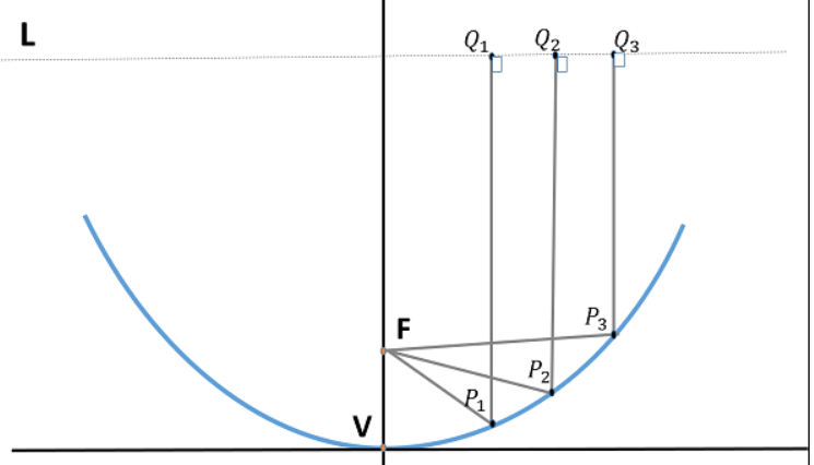
Fig 8 Parabolic Antenna
The reflected wave forms a collimated wave front, out of the parabolic shape. The ratio of focal length to aperture size (i.e., f/D) known as “f over D ratio” is an important parameter of parabolic reflector. Its value varies from 0.25 to 0.50.
The law of reflection states that the angle of incidence and the angle of reflection are equal. This law when used along with a parabola, helps the beam focus. The shape of the
parabola when used for the purpose of reflection of waves, exhibits some properties of the parabola, which are helpful for building an antenna, using the waves reflected.
All the waves originating from focus, reflects back to the parabolic axis. Hence, all the waves reaching the aperture are in phase.
As the waves are in phase, the beam of radiation along the parabolic axis will be strong and concentrated.
If a Parabolic Reflector antenna is used for transmitting a signal, the signal from the feed, comes out of a dipole or a horn antenna, to focus the wave on to the parabola. It means that, the waves come out of the focal point and strike the Paraboloidal reflector.
The gain of the paraboloid is a function of aperture ratio (D/λ). The Effective Radiated Power (ERP) of an antenna is the multiplication of the input power fed to the antenna and its power gain. Usually, a wave guide horn antenna is used as a feed radiator for the paraboloid reflector antenna. Along with this technique, we have another type of feed given to the paraboloid reflector antenna, called as Cassegrain feed.
Cassegrain is another type of feed given to the reflector antenna. In this type, the feed is located at the vertex of the paraboloid, unlike in the parabolic reflector. A convex shaped reflector, which acts as a hyperboloid is placed opposite to the feed of the antenna
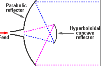
Fig 9 Cassegrain Feed
It is also known as secondary hyperboloid reflector or sub-reflector. It is placed such that it’s one of the foci coincides with the focus of the paraboloid. Thus, the wave gets reflected twice.
Key takeaway
The Cassegrain feed parabolic reflector is mainly used in satellite communications.
The parabolic reflector antenna gain is calculated as the gain over an isotropic source, i.e., relative to a source that radiates equally in all directions. This is a theoretical source that is used as the benchmark against which most antennas are compared. The gain is quoted in this manner is denoted as dBi.
The formula for antenna gain is
G = 10 log 10 k (πD/ )
)
G is the gain over an isotropic source in dB
k is the efficiency factor which is generally around 50% to 60%, i.e., 0.5 to 0.6
D is the diameter of the parabolic reflector in metres
λ is the wavelength of the signal in metres
The beamwidth of reflector antenna is given by

G is the gain over an isotropic source in dB
D is the diameter of the parabolic reflector
λ is the wavelength of the signal
All dimensions must be in the same units for the calculation to be correct, e.g., both diameter and wavelength in metres, or both in feet, etc.
Key takeaway
The formula for antenna gain is
G = 10 log 10 k (πD/ )
)
Analog microwave communication system include LOS and over the horizon (OTH) analog communication systems. LOS communication is limited by horizon due to earth’s curvature i.e., the transmission distance is determined by the height of the antenna above the earth in view of the horizon limitation. Microwaves are normally bent or refracted beyond the optical horizon (horizon visible to eyes). However due to atmospheric refractive changes, the radio horizon could even be less than the optical horizon at times.
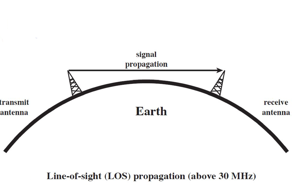
Fig 10 Line of Sight
The height of the microwave tower should be such that the radio beam is not obstructed by high rise buildings, trees or mountains. LOS microwave systems have shorter installation time, high flexible channel capacity and better adaptation to difficult terrains and natural barriers. LOS microwave system operates in the 14Hz to 10GHz frequency range. Above 10GHz however absorption due to rain, fog or snow may affect the system performance. Above 20GHz it is the absorption due to water vapour and atmospheric oxygen that limits the performance of an LOS system. Frequency Division Multiplexing (FDM) is used in all analog microwave LOS systems that enables several telephone signals to be transmitted over the same carrier. Normally the 4 KHz telephone channels are grouped as a 12-channel basic group in the frequency band 60KHz to 108KHz. Further, 5 basic groups form a 60-channel super group in the frequency band from 312KHz to 552KHz. 16 super groups are clubbed together to obtain a 960-channel master group.
Key takeaway
Attenuation of Microwaves by Atmospheric gases
The transfer of electromagnetic radiation through an atmosphere is linked to its state (temperature, pressure, and composition) by the refractive index and by coefficient of absorption and scattering, if any. The absorption coefficient in a medium is a macroscopic parameter that represents the interaction of incident electromagnetic energy with the constituent molecules. The interaction is governed by three general principles.
1. Bohr’s Frequency Condition: The frequency of a photon emitted or absorbed by the gas is equal to the difference of two energy levels (Ea-Eb) of the gas, divided by Plank’s constant h.
2. Einstein’s laws of emission and absorption: If Ea is higher than Eb, the probability, given initial state a, of stimulated emission of a photon by a transition from state a to state b is equal to the probability, given initial state b, of absorption of a photon by a transition from b to a. Hence the net absorption is proportional to the difference in thermodynamic probabilities (Pa-Pb) of two states.
3. Dirac’s Perturbation Theory: For the electromagnetic field to include transitions between states a and b, the operator with which the field interacts must have a non-zero matrix element linking the two states. For wavelengths that are very long compared to molecular dimensions, this operator is the dipole moment.
Attenuation of Microwaves Water Vapour & Precipitates.
Water vapor and fog are the most influencing parameters when microwave propagates through the atmosphere. At high frequencies above about 10GHz, electromagnetic radiation starts interacting with the neutral atmosphere and also with the various metrological parameters, in particular, precipitation, producing absorption of energy and thus attenuation of signal levels. In addition to absorption by molecular oxygen, molecules of water vapor also interact with electromagnetic radiation in the microwave and milli meter wave regions. The water vapor molecule being a permanent electric dipole produces rotational transitions of the order of 104 times stronger than that of the magnetic transitions of the oxygen molecule. So, even though the abundance of water vapor in the atmosphere is considerably less than the oxygen, it can produce significant level of attenuation near the resonant frequencies. Water vapor attenuation is found to depend quadratically on water vapor density, particularly at high densities, above about 12g/m3.
Key takeaway
Impedance (Z) is defined as the ability to oppose the flow of an alternating current (AC) at a given frequency. It is represented as a complex quantity and is graphically shown on a vector plane. An impedance vector consists of a real part (resistance, R) and an imaginary part (reactance, X).

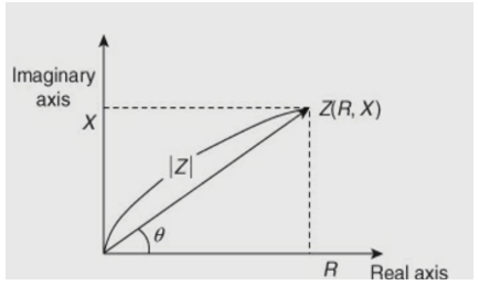
Fig 11 Plot for real and imaginary
There are many methods for measuring impedance, each of which has advantages and disadvantages. The most commonly used method is the measurement of impedance using the slotted line.
Measurement of Impedance Using a Slotted Line:
The end of the slotted line is connected to the unknown impedance. From the other end of the coaxial line microwave power is fed. A part of the power is reflected by 

the unknown impedance. By evaluating the standing wave fields in the slotted line this reflection coefficient is measured. The reflection coefficient Γ, is given by
Where, the unknown impedance terminating a line of characteristic impedance is. Thus, can be determined, if Γ is measured and is known. As is complex, from the VSWR measurement both the magnitude and phase of Γ can be determined.


Fig 12 VSWR measurement
VSWR and (difference of two successive minima) are noted by moving the probe and observing the output on a VSWR meter. Knowing the VSWR and a graphical construction on Smith chart may be used to calculate the unknown impedance.
Key takeaway
VSWR measurement both the magnitude and phase of Γ can be determined.

the reflection coefficient Γ, is given by

The gain of pyramidal horn antenna is given by
Gain = 4πAeA/ 2
2
Then for a conical horn the gain formula can be shown to be:
Gain = (πDeA/ )2
)2
Where;
A is the physical area of the aperture
d is the physical diameter of a conical horn aperture
λ is the wavelength
eA is the aperture efficiency and is a figure between 0 and 1
The horn antenna can operate very effectively. The flare of the horn antenna provides a smooth match between the waveguide and free space and its angle affects many properties including the gain and directivity.
Experimental way of measurement of gain
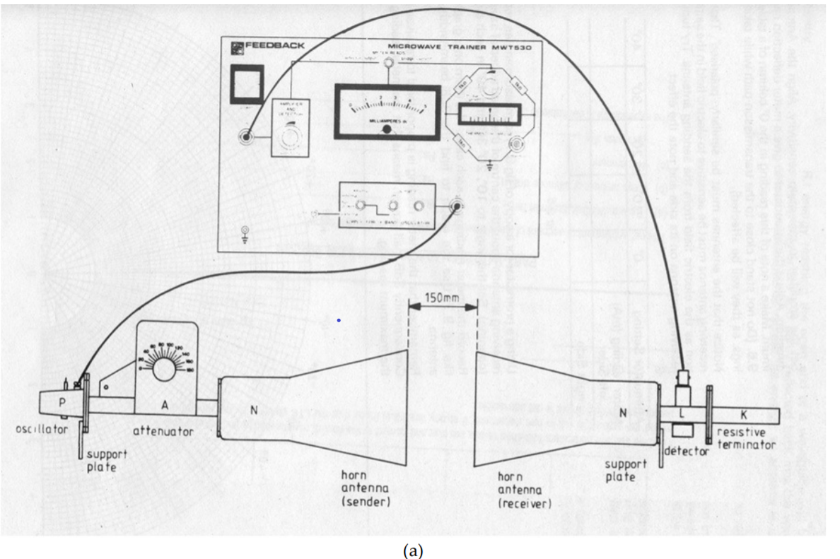
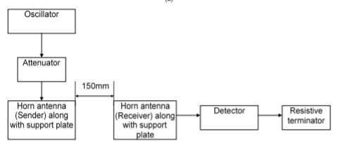
Fig 13 Antenna test-bench set-up for radiation pattern measurement (a) Schematic and (b) Block diagram
1. Set up the equipment as shown in figure (this is also known as two antenna methods since we are using two identical horn antennas at the transmitter and receiver with same gain).
2. Keep the range dB switch of VSWR meter at 50 dB position with gain control full.
3. Energize the Gunn oscillator (or Klystron Amplifier) for maximum output at desired frequency.
4. Obtain full scale deflection at VSWR meter with variable attenuator.
5. Obtain the reading at the VSWR meter at the receiving antenna and record it.
6. Without touching gain control knob, replace the transmitting horn by detector mount and change the appropriate range dB position to get the deflection on scale. Note and record the range dB position and deflection of VSWR meter.
7. Calculate the difference in dB between the power measured in step 4 and 5. Then calculate the gain as explained in the following example. 8. Radiation efficiency can be calculated as

EXAMPLE
Suppose that a deflection of 5 dB on 20 dB range dB position was obtained in step 5, the difference between 4 and 5 is 50 – (20 – 5) = 25 dB. Convert the dB into power ratio. As for above example, it will come out to be 316, which will be Pt/Pr. Calculate gain by following equation:
G = 4 π/ λ0√(Pr/Pt)
In our above example, suppose operating frequency is 9GHz. So, λ0 = 3.33cm. c is velocity of light and is 3 10 ×10 cm/sec. Suppose the distance between antennas is 15 cm.
9. Convert G into dB in above example G dB = 10 log 318 = 15.02 dB
10. The same setup can be used for other frequency of operation.
References:
[1] Microwave Engineering by D. M. Pozor, 2nd Edition. John Willy & Sons. Selected portions from Chapter 2, 3, 4, 6, 7 & 9.
[2] Principles of Microwave Engineering by Reich, Oudong and Others.
[3] Microwave Device and Circuit, 3rd Edition, Sammuel Y., Liao, Perason
[4] Microwave Devices and Circuits, G S N Raju