Unit - 1
History of wireless communication
Revolution of Wireless
Photo phone
Electric Wireless Technology
Radio Waves
Revolution
Key takeaway
Mobile simply describes a computing device that is not restricted to a desktop. A mobile device may be a PDA, a “smart” cell phone or Web phone, a laptop computer, a tablet PC or any one of numerous other devices that allow the user to complete computing tasks without being physically connected to a network.
In the last two centuries, mobility has been redefined. Both physical and virtual objects are now mobile.
- Mobility of physical objects relate to movement of matters,
- Whereas movements of virtual objects relate to movements of bits and bytes.
A simple definition could be:
Mobile Computing is using a computer (of one kind or another) while on the move
OR
Mobile Computing is when a (work) process is moved from a normal fixed position to a more dynamic position
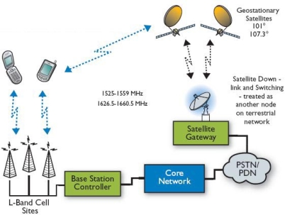
Fig 1 General structure of mobile computing
Why we use mobile computing
Mobile Computing Functions
A computing environment is defined as mobile if it supports one or more of these characteristics
- User should be able to move from one physical location to another location and use same service
- The service could be in the home network or a remote network.
- Example could be a user moves from London to New York and uses Internet to access the corporate application the same way the user uses in the home office.
- User should be able to move from one network to another network and use same service
- User should be able to move from one device to another and use same service.
- Example could be a user moves from Hong Kong to New Delhi and uses the same GSM phone to access the corporate application through WAP (Wireless Application Protocol). In home network he uses this service over GPRS (General Packet Radio Service) whereas in Delhi he accesses it over the GSM network
- A user session should be able to move from one user-agent environment to another.
- User should be able to move from one service to another
- Example could be a user is writing a mail. To complete the mail user needs to refer to some other information. In a desktop PC, user simply opens another service (browser) and moves between them using the task bar. User should be able to switch amongst services in small footprint wireless devices like in the desktop.
- The user should can be either a client or server
- When it is a server or host, some of the complexities change.
- In case of host mobility, the mobility of IP needs to be taken care of.
Logical Functions of Mobile Computing
The mobile computing functions can be logically divided into following major segments
- The user device, this could be a fixed device like desktop computer in office or a portable device like mobile phone.
- Example: laptop computers, desktop computers, fixed telephone, mobile phones, digital TV with set-top box, palmtop computers, pocket PCs, two-way pagers, handheld terminals, etc.
2. Network:
- Whenever a user is mobile, he will be using different networks at different places at different time.
- Example: GSM, CDMA, iMode, Ethernet, Wireless LAN, Bluetooth etc.
3. Gateway:
- This is required to interface different transport bearers.
- These gateways convert one specific transport bearer to another transport bearer.
- Example: From a fixed phone (with voice interface) we access a service by pressing different keys on the telephone. These keys generate DTMF (Dual Tone Multi Frequency) signals.
- These analog signals are converted into digital data by the IVR (Interactive Voice Response) gateway to interface with a computer application
4. Middleware:
- This is more of a function rather than a separate visible node.
- In the present context middleware handles the presentation and rendering of the content on a particular device.
- It will also handle the security and personalization for different users
5. Content:
- This is the domain where the origin server and content is.
- This could be an application, system, or even an aggregation of systems.
- The content can be mass market, personal or corporate content.
- Origin server will have some means to accessing the database and the storage devices.
Key takeaway
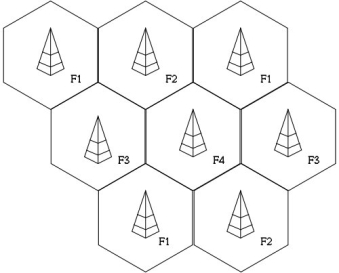
Fig 2. The Cellular Model
Key takeaway
The cellular system is replaced by large number of base stations (BS) which are hexagonal cells. They cover certain range of areas.
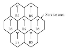
Fig 3 Cellular Structure
For having the communication in cellular structure, we need Mobile station (MS). In these types of structures, the MS communicates with the BS of cell. This is the location of MS in a BS cell. This BS acts as a gateway. For establishing connections, the MS needs to be in the range of the system. The figure below shows the same.
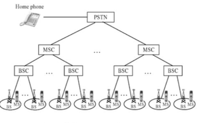
Fig 4 Cellular system infrastructure
Each base station controller (BSC) consists of MS and a BS. These BSC are then connected to the Mobile switching Centre (MSC). These MSC are then connected to a Public Switch Telephone Network (PSTN) and the Asynchronous Transfer Mode (ATM).
A base station consists of several base transceiver stations (BTS) and a BSC. The antenna and tower are the parts of BTS. The BTS system consists of towers and antennas.
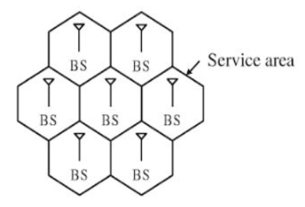
Fig 5 Generic block diagram of cell structure
The Home location register (HLR) is located at MSC. The MS is registered there only in the home location. The visitor location register (VLR) and HLR support mobility and helps to use one number i.e., same number anywhere in world. The VLR has information about all MS.
The authentication and encryption are provided by Authentication centre (AUC). The database which provides identity and information about the mobile is equipment identity register (EIR).
Whenever there is a call, it is directed to HLR where home MS is registered. This is then forwarded to VLR of MSC where MS is located currently.
Key takeaway
Space Division Multiplexing
Frequency Division Multiplexing
Time Division Multiplexing
Key takeaway
Methods for improving capacity in cellular systems
– Cell Splitting: subdividing a congested cell into smaller cells.
– Sectoring: directional antennas to control the interference and frequency reuse.
– Coverage zone: Distributing the coverage of a cell and extends the cell
boundary to hard-to-reach place.
Cell splitting
The concept of Cell Splitting is quite self-explanatory by its name itself. Cell splitting means to split up cells into smaller cells. The process of cell splitting is used to expand the capacity (number of channels) of a mobile communication system. As a network grows, a quite large number of mobile users in an area come into picture. Consider the following scenario.
There are 100 people in a specific area. All of them owns a mobile phone (MS) and are quite comfortable to communicate with each other. So, a provision for all of them to mutually communicate must be made. As there are only 100 users, a single base station (BS) is built in the middle of the area and all these users’ MS are connected to it. All these 100 users now come under the coverage area of a single base station. This coverage area is called a cell. This is shown in Figure.
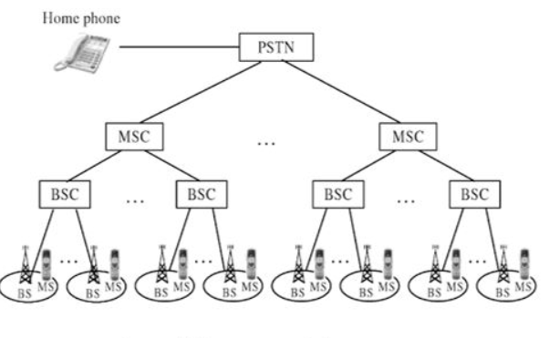
Fig.6 A single BS for 100 MS users.
But now, as time passed by, the number of mobile users in the same area increased from 100 to 700. Now if the same BS has to connect to these 700 users’ MS, obviously the BS will be overloaded. A single BS, which served for 100 users is forced to serve for 700 users, which is impractical. To reduce the load of this BS, we can use cell splitting. That is, we will divide the above single cell into 7 separate adjacent cells, each having its own BS. This is shown in Fig below.
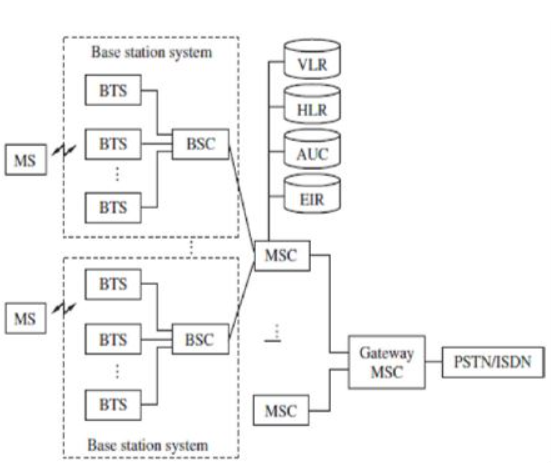
Fig.7 Single cell split up into 7 cells.
Now, let us look into the big picture. Until now, we have discussed about cell splitting in a small area. Now, we use this same concept to deal with large networks. In a large network, it is not necessary to split up all the cells in all the clusters. Certain BSes can handle the traffic well if their cells (coverage areas) are split up. Only those cells must be ideal for cell splitting. Fig below shows network architecture with a few numbers of cells split up into smaller cells, without affecting the other cells in the network.
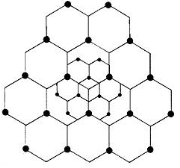
Fig.8 Cell Splitting
The concept of cell splitting can further be applied to the split cells as well. That is, the split up cells can further be split into a number of smaller cells to improve the efficiency of the BS even more. Fig above shows a hierarchy of cell splitting.
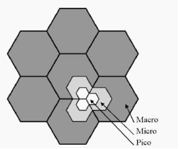
Fig.9 Cell Splitting of Split up cells.
Here, the master cells which have been split up into smaller cells are known as macro cells. The split up cells is known as micro cells. The innermost cells, split up by splitting the micro cells are known as pico cells.
Cell Sectoring
In cellular telephone system, co-channel interference can be decreased by replacing a single omnidirectional antenna with several directional antennas, each radiating within a smaller area.
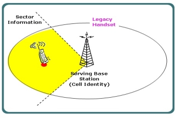
Fig.10 Cell Sectoring
Another way of improving the channel capacity of a cellular system is to decrease the D/R ratio while keeping the same cell radius. Improvement in the capacity can be accomplished by reducing the number of cells in a cluster, hence increasing the frequency reuse. To achieve this, the relative interference must be minimized without decreasing the transmit power.
For minimizing co-channel interference in a cellular network, a single Omni-directional antenna is replaced with multiple directional antennas, with each transmitting within a smaller region. These smaller regions are called sectors and minimizing co-channel interference while improving the capacity of a system by using multiple directional antennas is called sectoring.
The amount up to which co-channel interference is minimized depends on the amount of sectoring used. A cell is generally divided either into three 120 degree or six 60-degree sectors. In the three-sector arrangement, three antennas are generally located in each sector with one transmit and two receive antennas.
When sectoring technique is used in cellular systems, the channels used in a particular sector are actually broken down into sectored groups, which are only used inside a particular sector. With 7-cell reuse pattern and 120-degree sectors, the number of interfering cells in the neighbouring tier is brought down from six to two.
Cell sectoring also improves the signal-to-interference ratio, thereby increasing the capacity of a cellular system. This method of cell sectoring is very efficient, because it utilized the existing system structures.
Cell sectoring also minimized the co-channel interference, with the use
of directional antennas, a particular cell will get interference and transmit only a fraction of the available co-channel cells.
Repeaters for rang extension
A wireless repeater (also called wireless range extender) takes an existing signal from a wireless router or access point and rebroadcasts it to create a second network. When two or more hosts have to be connected with one another and the distance is too long for a direct connection to be established, a wireless repeater is used to bridge the gap. It can be a specialized standalone computer networking device. Wireless repeaters are commonly used to improve signal range and strength within homes and small offices.
Wireless operators want to provide dedicated coverage for users located within buildings, or in valleys or tunnels as these areas are sometimes very hard to reach. Radio retransmitters, also known as repeaters, are frequently used to provide coverage in such areas where range extension capabilities are required. Repeaters are bidirectional devices, as the signals can be concurrently transmitted to and received from a base station.
Repeaters may be installed anywhere as they function using over the air signals, and are able repeat entire frequency band. After receiving signals from base station, the repeater amplifies the signals before it forwards them to the coverage area.
As repeaters can also reradiate the received noise, so repeaters must be installed very carefully. Directional antennas or distributed antenna system (DAS) are linked practically to the repeater inputs or outputs for spot coverage, mainly in tunnels or buildings.
Microcell Zone Concept
The micro-cell zone concept is associated with sharing the same radio equipment by different micro-cells. It results in decreasing of cluster size and, therefore, increase in system capacity. The micro-cell zone concept is used in practice to improve the capacity of cellular systems.
To improve both capacity and signal quality of a cellular system, cell sectoring depends upon correct setting up of directional antennas at the cell-site. But it also gives rise to increase in the number of handoffs and trunking inefficiencies. In a 3-sector or 6-sector cellular system, each sector acts like a new cell with a different shape and cell.
Channels allocated to the un-sectored cell are divided between the different sectors present in a cell, thereby decreasing number of channels available in each sector. Furthermore, handoff takes place every time a mobile user moves from one sector to another sector of the same cell.
This results in significant increase of network load on BSC and MSC of the cellular system. The problem of channel partitioning and increase in network load become very hard if all the 3 or 6-sectored directional antennas are placed at the centre of the cell.
As shown in the Fig., three directional antennas are put at a point, Z1, also called zone-site, where three adjacent cells C1, C2, and C3 meet with each other. Z1, Z2 and Z3 are three zone-sites of the cell C1, and each zone-site is using three 135-degree directional antennas. All the three zone-sites also behave as receivers, which also receive signals transmitted by a mobile user present anywhere in the cell.
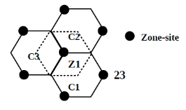
Fig.11 Location of zone site in sectored cell
All the three zone-sites are linked to one common base station, as shown in Fig. This arrangement is known as Lee's micro-cell zone concept.
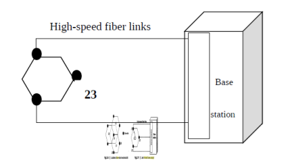
Fig. 12 Lee’s Microcell zone concept
Key takeaway
1. When the mobile user moves from one zone to another within the same cell, the mobile user can keep the same channel for the call progress.
2. The effect of interference is very low due to the installation of low power transmitters.
3. Better signal quality is possible.
4. Fewer handoffs when a call is in progress.
Co-channel interference
Co-channel interference or CCI is crosstalk from two different radio transmitters using the same frequency.
Co-channel interference occurs between two access points (APs) that are on the same frequency channel. The reason that you should care is that co-channel interference can severely affect the performance of your wireless LAN (WLAN).
Co-channel interference is more problematic when you deploy your WLAN to support voice or RFID location tagging. These types of scenarios require a denser deployment of APs. Denser deployments mean that your APs are closer together. And that creates a greater potential of two devices that transmit on the same frequency channel will be close enough to cause significant interference to each other's signals.
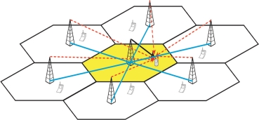
Fig 13 Co-channel interference
There can be several causes of co-channel radio interference; four examples are listed here.
In cellular mobile communication (GSM & LTE Systems, for instance), frequency spectrum is a precious resource which is divided into non-overlapping spectrum bands which are assigned to different cells (In cellular communications, a cell refers to the hexagonal/circular area around the base station antenna).
However, after certain geographical distance, the frequency bands are re-used, i.e., the same spectrum bands are reassigned to other distant cells. The co-channel interference arises in the cellular mobile networks owing to this phenomenon of Frequency reuse.
Thus, besides the intended signal from within the cell, signals at the same frequencies (co-channel signals) arrive at the receiver from the undesired transmitters located (far away) in some other cells and lead to deterioration in receiver performance.
During periods of uniquely high-pressure weather, VHF signals which would normally exit through the atmosphere can instead be reflected by the troposphere. This tropospheric ducting will cause the signal to travel much further than intended; often causing interference to local transmitters in the areas affected by the increased range of the distant transmitter.
In the Medium frequency portion of the radio spectrum where most AM broadcasting is allocated, signals propagate full-time via groundwave and, at night time, via sky wave as well. This means that during the night time hours, co-channel interference exists on many AM radio frequencies due to the medium waves reflecting off the ionosphere and being bounced back down to earth. In the United States, Canada, Mexico, and the Bahamas, there are international agreements on certain frequencies which allocate "clear-channel" broadcasting for certain stations to either have their respective frequencies to themselves at night, or to share their respective frequencies with other stations located over hundreds or even thousands of miles away.
On other frequencies, there are "Regional Channels" where most stations on these frequencies either reduce power or change to a directional antenna system at night time to help reduce co-channel interference to each other's signals. In the United States, there are six "Local Channel" frequencies, also known as "grave yarders" where nearly every station on those frequencies has the same power and antenna pattern both day and night and, as a result of sky wave propagation, there is normally massive co-channel interference in rural areas on these frequencies, often making it difficult, if not impossible, to understand what's being said on the nearest local station on the respective channel, or the other distant stations which are bouncing on the same channel, during the night time hours.
Adjacent channel Interference
Adjacent-channel interference (ACI) is interference caused by extraneous power from a signal in an adjacent channel.
Adjacent channel interference (ACI) is interference between links that communicate geographically close to each other using neigh boring frequency bands. For instance, several network operators may deploy their own networks in the same area and operate on frequency bands that are close to each other. Hence, ACI needs to be taken into account in the system specifications so that it will not hamper the system performance.
Adjacent channel interference: interference from adjacent in frequency to the desired signal.
– Imperfect receiver filters allow nearby frequencies to leak into the passband
– Performance degrades seriously due to near-far effect.
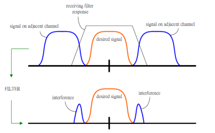
Fig 14 Adjacent channel
Adjacent channel interference can be minimized through careful filtering and channel assignment.
• Keep the frequency separation between each channel in a given cell as large as possible
• A channel separation greater than six is needed to bring the adjacent channel interference to an acceptable level.
Location management enables the networks to track the locations of mobile nodes. Location management has two major sub-tasks: (i) location registration, and (ii) call delivery or paging. In location registration procedure, the mobile node periodically sends specific signals to inform the network of its current location so that the location database is kept updated. The call delivery procedure is invoked after the completion of the location registration. Based on the information that has been registered in the network during the location registration, the call delivery procedure queries the network about the exact location of the mobile device so that a call may be delivered successfully. The design of a location management scheme must address the following issues:
(i) Minimization of signaling overhead and latency in the service delivery,
(ii) Meeting the guaranteed quality of service (QoS) of applications, and
(iii) In a fully overlapping area where several wireless networks co-exist, an efficient and robust algorithm must be designed so as to select the network through which a mobile device should perform registration, deciding on where and how frequently the location information should be stored, and how to determine the exact location of a mobile device within a specific time frame.
Following figure demonstrates the case where a handoff is not made and the signal drops below the minimum acceptable level to keep the channel active. This dropped call event can happen when there is an expansive delay by the MSC in assigning a handoff or when the threshold is set too small for the handoff time in the systems. Excessive delay may occur during high traffic conditions or due to no channels are available on any of the nearby base stations.
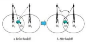
Fig 15 Hand off strategy
In deciding when to handoff, it is important to ensure that the drop in the measured signal is not due to momentary fading and the mobile is actually moving away from the serving base station. But when there is a drop in the measured signal level due to momentary fading and not due to the actual moving mobile away from the base station, that is situation if the handoff of a call takes place, then such handoffs must be prevented by ensuring that the base station monitors the signal level for a certain period of time before the handoff is initiated.
Three strategies have been proposed
The MS continuously monitors the signal of surrounding BSs and initiate the handoff process when some handoff criteria are met. MCHO is used in DECT
(Digital Enhanced Cordless Telecommunications)
2. In network-controlled handoff (NCHO)
The surroundings BSs measure the signal from the MS, 7 the network initiates the handoff process when some handoff criteria are met.
3. In mobile-assisted handoff (MAHO)
The network asks the MS to measure the signal from the surrounding BSs. The network makes the handoff decision based on report from the MS. MAHO is used in GSM & IS-95 CDMA
Key takeaway
This handoff operation not only involves identifying a new base station, but also requires that the voice and control signals be allocated to channels associated with the new base station.
Mobile IP, the outcome of the convergence of mobile communication technologies and the IP network, is the core technology to implement NGN applications in traditional networks. It supports network mobility, two-way access, and real-time multimedia services
As a recommended Internet standard, Mobile IP is the earliest solution to mobility management of IP network. The IETF (Internet Engineering Task Force) gives a complete description of Mobile IP in RFC2002. Along with the development of IPv4 to IPv6, Mobile IP is also evolving to Mobile IPv6.
With the growth of telecommunications, it is inevitable to introduce and develop the Mobile IP technology. The huge market demand drives the growth of Mobile IP. Besides, the technologies of General Packet Radio Service (GPRS), Wireless Local Area Network (WLAN) and CDMA2000 1X are also boosting the development of Mobile IP, providing a platform for the implementation of Mobile IP services.
1 Problems with Mobile IP
Although growing rapidly, Mobile IP still has the following problems:
(1) "Triangle routing" Problem
The Communication Host (CH) has to send packets to the Mobile Host (MH) via the Home Agent (HA), while the MH sends packets directly to the CH. As the communication in the two directions follows different routes, the problem of "triangle routing" arises, which leads to low efficiency especially when the MH is far away from the HA and the CH is near to the MH.
(2) Handoff Problem
Handoff problem means that the HA sends the IP packets of the MH to the original foreign network via the tunnel because it doesn’t know the latest Care of Address (CoA) of the MH during the period starting when the MH leaves the original foreign network and ending when the HA receives the new registration address of the MH. As a result, these dropped IP packets have an influence on the communication between the MH and the CH especially when handoff occurs frequently or the MH is far away from the HA.
(3) Problem of Intra-Domain Movement
The frequent intra-domain movement of the MH within a small area will lead to frequent handoff. Consequently, a great amount, of registered messages are generated in the network and the network performance is greatly affected.
(4) QoS Problem
In the mobile environment, it is hard to provide QoS over Mobile IP due to dynamically varying wireless network topologies, limited network resources, unpredictable effective bandwidth and high error rate.
Key takeaway
Problems of mobile IP are Triangle routing problem, handoff problem, problem of intra-domain movement and QoS problem.
References:
[1] Wireless Communications- Principles and Practice, T S Rappaport, Pearson Education India, Second Edition.
[2] Wireless Communication and Networks, Upen Dalal, Oxford university Press, First Edition, 2015.
[3] Wireless Communication and Networks 3G and Beyond, Iti Saha Misra, Tata
McGraw Hill Education Pvt. Ltd, Second Edition, 2009.
[4] Mobile Communication Engineering – Theory and Applications W C Y Lee, TMH Publication, Second Edition, 2008.
[5] Wireless Communication, Andrea Goldsmith, Cambridge University Press, 2005
[6] Fundamentals of Wireless Communication, David Tse and Pramod Viswanath,
Cambridge University Press, 2005