Unit – 1
Concept of Stress
In easy phrases we will outline pressure because the pressure of resistance in line with unit in line with unit area, presented via way of means of a frame in opposition to deformation.
Stress is the ratio of pressure over area (S =R/A, in which S is the pressure, R is the inner resisting pressure and A is the cross-sectional area).
Stress is the degree of an outside pressure appearing over the move sectional vicinity of an object. Stress has gadgets of pressure consistent with vicinity: N/m2 (SI)
Normal Stress and Shear Stress When a pressure acts perpendicular (or "ordinary") to the floor of an object, it exerts a ordinary stress.
Key takeaways:
- Stress is the ratio of pressure over area (S =R/A, in which S is the pressure, R is the inner resisting pressure and A is the cross-sectional area).
- Stress is the degree of an outside pressure appearing over the move sectional vicinity of an object. Stress has gadgets of pressure consistent with vicinity: N/m2 (SI)
- Normal Stress and Shear Stress When a pressure acts perpendicular (or "ordinary") to the floor of an object, it exerts a ordinary stress.
In mechanics, stress is defined as a force applied per unit area. It is given by the formula
σ=F/A
Where,
σ is the stress applied
F is the force applied
A is the area of force application
The unit of stress is N/
Maximum principle strain theory is also known as St. Venant’s theory
This theory state as that the material subjected to complex stresses will fails when the maximum principle strain in it reaches the value of strain at yield point in a simple tensile test on materials
If  are the principle stresses acting on three mutually perpendicular planes then maximum principle strain (e1) for no failure condition is given by,


 where e1 must be positive and e3 must be negative
This equation shows the maximum principle strain  may be greater than
  which is unexpected condition in machine component so this theory is very little consideration
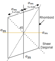
For two direction stress maximum principle strain theory is represented is shown in fig which is rhombus failure envelope.
Key takeaway:
- Maximum principle strain theory is also known as St. Venant’s theory
- This equation shows the maximum principle strain
 may be greater than
  which is unexpected condition in machine component so this theory is very little consideration
 - For two direction stress maximum principle strain theory is represented is shown in fig which is rhombus failure envelope.
The superposition theorem states that a circuit with more than one voltage and modern re assets is same to the sum of simplified circuits the use of simply one of the re assets
Superposition Principle shall we us calculate the entire pressure on a given price because of any range of factor costs appearing on it. Every charged particle creates an electric powered subject within side the universe within side the area surrounding it.
The electric powered subject created because of the price is unbiased of the presence or absence of all different costs. The electric powered subject created may be calculated with the assist of Coulomb’s law.
The precept of superposition lets in for the aggregate of or extra electric powered fields.
For our comfort allow us to recall one effective charge, and bad prices exerting a pressure on it, from the superposition theorem we recognize that the consequent pressure is the vector sum of all of the forces performing at the body, consequently the pressure Fr , the consequent pressure may be given as follows,
Continuous Charge Distribution: We understand that the smallest form of charge we're capable of benefit ought to be +e or –e i.e. the charge of an electron or a proton, for that reason charges are quantized.
Continuous charge distribution approach that all charges are cautiously positive together having very a good deal much less place amongst each other.
There are distinct tactics in which charges can be allocated: Linear charge distribution. Surface charge distribution.
Volume charge distribution
Linear charge distribution: The linear charge distribution is while the charges get allocated uniformly along a length, like throughout the circumference of a circle or along a right away wire, linear charge distribution is denoted through manner of way of the photo λ. λ = dq/dl and it is measured in Coulombs consistent with meter. Surface charge distribution: When a charge is distributed over a selected place, similar to the ground of a disk, it is called a ground charge distribution; it is denoted through manner of way of the Greek letter σ.
The ground charge distribution is measured Coulombs consistent with square meter or Cm-2.
Volume rate distribution: When a rate is sent uniformly over a extent it's miles stated to be extent rate distribution, like distribution of rate internal a sphere, or a cylinder. It is denoted through ρ. The extent rate distribution is measured in coulombs in keeping with cubic meter or Cm-3.
Key takeaways:
- The superposition theorem states that a circuit with more than one voltage and modern re assets is same to the sum of simplified circuits the use of simply one of the re assets
- Superposition Principle shall we us calculate the entire pressure on a given price because of any range of factor costs appearing on it.
- Every charged particle creates an electric powered subject within side the universe within side the area surrounding it.
According to the strain definition, it is defined as the amount of deformation experienced by the body in the direction of force applied, divided by initial dimensions of the body. The relation for deformation in terms of length of a solid is given below.

Where,
 is the strain due to stress applied
 is the change in length
L is the original length of the material.
The strain is a dimensionless quantity as it just defines the relative change in shape.
Depending on stress application, strain experienced in a body can be of two types.
Numerical:
Q.1. A rectangular bar of steel 50 mm× 30mm is 1m long carries a pull of 93.9KN, find tensile stress in the bar , strain and change in length, Take E=200 GPa
Given:
P=93.9 KN=93.9×10³ N
b=50mm
t=30mm
L=1m=1000mm
E=200GPa=200×103 MPa
Tensile stress  = P/A =
 = 62.6MPa
Tensile strain, E=σ/e
∴ e = σ/E =  =3.13 ×10⁻⁴
Change in length e= /L
/L
∴δL = eL =3.13 =0.313 mm
Alternative δL = =
=  =0.313mm
Q.2.A copper wire of length 600 mm is subjected to an axial pull of 10 KN. Find the minimum diameter so that stress is not to exceed 75 MPa. Also calculate the elongation of E=100 GPa.
Given:
P=10KN=10×10^3N
L=600mm
E= 100GPa = 100×10^3 MPa
Diameter of wire ‘d’ and elongation δL
 P/A
P/A
∴75=
A=133.33 mm2
 d^2 = 133.33
∴d = 13.03 mm
Elongation δL = =
= =0.45 mm
Q.3. Determine the value of safe axial pull for the rectangular bar as shown in fig. Thickness of bar is 15 mm throughout. Tensile stress in the bar should not exceed 120MPa.
Given:  = should not be more than 120MPa
Maximum stresses induced at the section having smaller cross sectional area.
Consider section 1-1 cutting first part of hole and 2-2 at second part
Area at 1-1 A1 =(b-d)t =(100-60)×15 = 600 mm2
Area at 2-2 A2 =80×15=1200mm2
∴Least cross sectional area A = 600 mm2
∴ Safe load P= σ × A=120×600=72000N=72KN
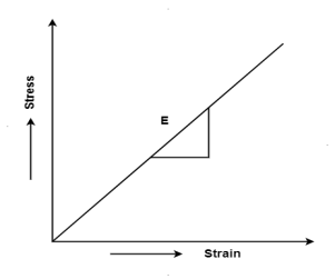
Hooke's law states that the strain of the material is proportional to the applied stress within the elastic limit of that material.
When the elastic materials are stretched, the atoms and molecules deform until stress is been applied and when the stress is removed, they return to their initial state
i.e., σ = E
Where,
σ is the stress
E is the modulus of elasticity also known as Young’s modulus
ε is the strain
When the stress is removed from the material, there are two types of deformation that can take place: plastic deformation and elastic deformation
Key takeaway:
- Hooke's law states that the strain of the material is proportional to the applied stress within the elastic limit of that material.
- When the elastic materials are stretched, the atoms and molecules deform until stress is been applied and when the stress is removed, they return to their initial state
- When the stress is removed from the material, there are two types of deformation that can take place: plastic deformation and elastic deformation
Different elastic constants are as follows:
- Young’s modulus
- Bulk modulus
- Rigidity modulus
- Poisson’s ratio
1. Young’s Modulus
According to Hooke’s law, when a body is subjected to tensile stress or compressive stress, the stress applied is directly proportional to the strain within the elastic limits of that body. The ratio of applied stress to the strain is constant and is known as Young’s modulus or modulus of elasticity.
Young’s modulus is denoted by letter “E”. The unit of modulus of elasticity is the same as the unit of stress which is megapascal (Mpa).
1 Mpa is equal to 1 N/mm2.

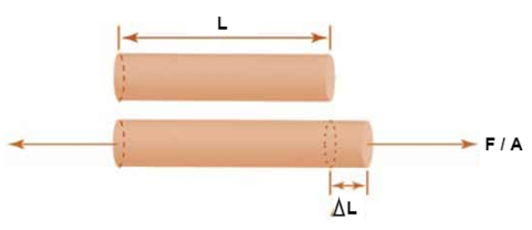
Fig: Body Subjected to Tensile Stress
2. Bulk Modulus
When a body is subjected to mutually perpendicular direct stresses which are alike and equal, within its elastic limits, the ratio of direct stress to the corresponding volumetric strain is found to be constant.
This ratio is called bulk modulus and is represented by letter “K”.
Unit of Bulk modulus is Mpa.

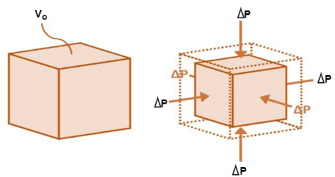
Fig: Volumetric Change of Body
3. Rigidity Modulus
When a body is subjected to shear stress the shape of the body gets changed, the ratio of shear stress to the corresponding shear strain is called rigidity modulus or modulus of rigidity.
It is denoted by the letters “G” or “C” or “N”.
Unit of rigidity modulus is Mpa.

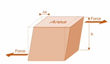
Fig: Shear Deformation of Body
4. Poisson’s Ratio
When a body is subjected to simple tensile stress within its elastic limits then there is a change in the dimensions of the body in the direction of the load as well as in the opposite direction.
When these changed dimensions are divided with their original dimensions, longitudinal strain and lateral strain are obtained.
The ratio of the lateral strain to the longitudinal strain is called Poisson’s ratio.
It is represented by the symbol “µ”. Poisson’s ratio is maximum for an ideal elastic incompressible material and its value is 0.5.
For most of the engineering materials, Poisson’s ratio lies between 0.25 and 0.33. It has no units.
1. Stress diagram
The internal resistance set up per unit cross sectional area is called as stress. It is denoted by 

In the equilibrium condition the internal resistance R is equal to an external load P
i.e., R=P

Where

P = load acting on the body
A = cross sectional area of the body
2. Strain Diagram:
Strain is simply a measure of deformation produced in a member due to the loads acting on it.
It is defined as the ratio of change in dimension to the original of the member

Key takeaway:
- The internal resistance set up per unit cross sectional area is called as stress. It is denoted by

- Strain is simply a measure of deformation produced in a member due to the loads acting on it.
- In the equilibrium condition the internal resistance R is equal to an external load P
It is defined as the ratio of the actual axial load and the original cross-sectional area of the specimen.

Working stress is the maximum allowable stress to which a material is subjected during its service load
For a safety of a structure, it is very essential that the working stress should be within the elastic limit of the material
The ratio of the ultimate stress to the working stress for a brittle material is called factor of safety.

The ratio of the yield stress to the working stress for a ductile material is called factor of safety

In designing to resist accidental loads sufficient reserve strength is required to be ensured which is called out by taking a suitable factor is called as factor of safety
Strain energy
When a load is applied on a elastic body it gets deformed i.e. the work is done by the load on the body
This work done is stored in a body is called as strain energy or resilience
When the load is removed the body regains to its original position because of stored energy
It can be easily visualized in springs when the springs is loaded it gets compressed and regain to its original position immediately when the load is removed
The amount of the strain energy stored in a body is depended on the type of loading i.e. axial load, bending load, shear load and torsion load etc.
Key takeaways:
- When a load is applied on a elastic body it gets deformed i.e. the work is done by the load on the body
- This work done is stored in a body is called as strain energy or resilience
- When the load is removed the body regains to its original position because of stored energy
1. Strain energy
When a load is applied on an elastic body it gets deformed i.e., the work is done by the load on the body
This work done is stored in a body is called as strain energy or resilience
When the load is removed the body regains to its original position because of stored energy
It can be easily visualized in springs when the springs is loaded it gets compressed and regain to its original position immediately when the load is removed
The amount of the strain energy stored in a body is depended on the type of loading i.e., axial load, bending load, shear load and torsion load etc.
2. Resilience:
The energy which is stored in a body within an elastic limit is called a strain energy or resilience it is denoted by U
3. Stress due to gradually applied load:
When a body is subjected to the gradually applied load, the stress increases from zero to the maximum value gradually
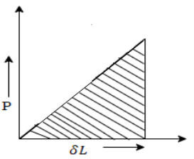
Let p= gradually applied load
 L = Extension due to load
 = maximum stress induced in the member


Strain energy stored in body

But Work done = Strain Energy stored


4. Stress due to suddenly applied load
When the load acting on a body is sudden the body gets deformed immediately after applying load for e.g., Weight of truck enter on weighing machine is an example of sudden load
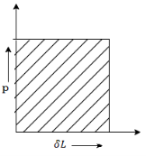
Let P= suddenly applied load


Work done by load = Area under curve
= P.
Strain energy stored in a body = 
But work done = strain energy stored


Stress due to sudden load is twice the stress due to gradually applied load.
4. Stresses due to Impact load
When a load applied on a body is falls from a certain height is called as impact or falling load
Consider a member is fixed at its top and a collar is attached to its lower end as shown in fig.
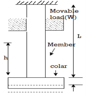
Let, W= weight of movable load
H = height of fall
L= length of member
A = cross sectional area
 L: = Deformation of length
 = Instateneous stress
Work done by external movable load = W (h+ )
)

But work done by load = Energy Stored in member


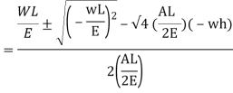

Multiplying both numerator and denominator by E/2E we get,

Maximum instantaneous stress

But 


The dimensionless ratio  is called as load factor and it is denoted by n

Structural additives subjected most effective to anxiety or compression: coil springs, stable bars with directly longitudinal axes, cables, etc.
Axial loaded member : structural additives subjected best to anxiety or compression, which includes trusses, connecting rods, columns, etc. alternate in duration for prismatic bars, non uniform bars are determined, it might be used to clear up the statically indeterminate structures, alternate in duration with the aid of using thermal impact is likewise considered stresses on willing sections might be calculated numerous extra subjects of significance in mechanics of substances might be introduced, which includes stress energy, effect loading, fatigue, stress concentrations, and nonlinear behavior, etc.
Changes in Length of Axial Loaded Members don't forget a coil spring with herbal period L subjected to an axial load P if the cloth of the spring is linear elastic then,


With

Prismatic bar: a member having directly longitudinal axis and constant move section remember a prismatic bar with move-sectional vicinity A and period L subjected to an axial load P


A composite bar is one product of materials, which include metal rods embedded in concrete. The production of the bar is such that constituent additives expand or agreement similarly below load. To illustrate the behavior of such bars bear in mind a rod product of materials, 1 and 2, Figure ; A,, A, are the cross-sectional regions of the bars, and E,, E, are the values of Young's modulus. We believe the bars to be rigidly related collectively on the ends; then for compatibility, the longitudinal lines to be the equal while the composite bar is stretched we ought to have

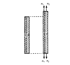
Where sigma 1, and sigma 2 are the stresses in the two bars. But from equilibrium considerations,


Key takeaways:
- Structural additives subjected most effective to anxiety or compression: coil springs, stable bars with directly longitudinal axes, cables, etc.
- Axial loaded member: structural additives subjected best to anxiety or compression, which includes trusses, connecting rods, columns, etc.
- Alternate in duration for prismatic bars, non uniform bars are determined, it might be used to clear up the statically indeterminate structures, alternate in duration with the aid of using thermal impact
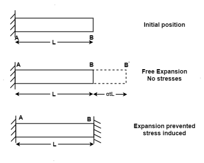
When the expansion or Contraction of the member due to temperature variation is prevented the stresses induced in the member is called Temperature stresses
When the Temp is rise, the stresses induced in the member are compressive in nature.
When Temp falls, the stresses induced are Tensile in nature
We know, 


Where, = Coefficient of thermal expansion in 1 C or 1
 k
k
T = Temperature Variation in  or K.
or K.
E = Young’s Modulus,
In statics and structural mechanics, a shape is statically indeterminate whilst the static equilibrium equations - pressure and second equilibrium conditions - are inadequate for figuring out the inner forces and reactions on that shape
Based on Newton's legal guidelines of motion, the equilibrium equations to be had for a two-dimensional frame are:


∑ F → = 0 }=0} sum =0: the Victoria sum of the forces appearing at the frame equals zero.
This interprets to: ∑ H → = 0} =0} }=0}: the sum of the horizontal additives of the forces equals zero; ∑ V → = 0} =0} }=0}: the sum of the vertical additives of forces equals zero;
∑ M → = 0} =0} sum =0: the sum of the moments (approximately an arbitrary point) of all forces equals zero.
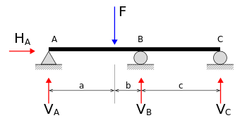
Free frame diagram of a statically indeterminate beam. In the beam production at the right, the 4 unknown reactions are VA, VB, VC, and HA. The equilibrium equations
Since there are 4 unknown forces (or variables) (VA, VB, VC and HA) however simplest 3 equilibrium equations, this machine of simultaneous equations does now no longer have a completely unique solution.
The shape is consequently categorized as statically indeterminate. To resolve statically indeterminate systems (decide the diverse second and pressure reactions inside it), one considers the fabric residences and compatibility in deformations.
Structures for which inner forces and reactions cannot be decided from statics by myself are said to be statically indeterminate.
Deformations because of real masses and redundant reactions are decided one after the other after which added or superpose shape may be statically indeterminate every time it's far held through extra helps than are required to keep its equilibrium. Redundant reactions are changed with unknown masses which together with the other masses have to produce well matched deformations.

The shear force at the cross section of a beam is defined as the algebraic sum of all the unbalanced vertical forces either left or right of the section.
SF = (∑ Fy)L = (∑ Fy) R
Sign convention for shear force:
An upward force to the left of section or downward force to the right of a section will be considered as a positive shear force.
When the force is downward to the left side of section and upward on the right of a section, will be considered as a negative shear force.
When two equal opposite and parallel force acting tangential to the surface of the body is called as shear stress
Shear strain, pressure tending to motive deformation of a cloth via way of means of slippage alongside a aircraft or planes parallel to the imposed strain.
Shear strain can also additionally arise in solids or liquids; within side the latter it's miles associated with fluid viscosity.
Key takeaways:
- The shear force at the cross section of a beam is defined as the algebraic sum of all the unbalanced vertical forces either left or right of the section.
- SF = (∑ Fy)L = (∑ Fy) R
Principle of complementary shear stresses
In order to balance the rectangular block, there must be one more couple of similar intensity acting over the rectangular block in opposite direction i.e. in anti clockwise direction
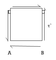
Let us keep in mind a square block ABCD as displayed in following figure. Let us expect that a fixed of shear stresses (τ) of contrary course, as displayed in following figure, is implemented over the other surfaces of square block i.e. AB and CD.
Now if we keep in mind the impact of this set of shear stresses (τ) of contrary course, we are able to effortlessly say that there could be 0 internet pressure performing over the square block however there will be one couple performing over the square block in clockwise course.
In order to stability the square block, there need to be one greater couple of comparable depth performing over the square block in contrary course i.e. in anti clockwise course. Therefore, there could be one greater set of shear stresses (τ’) of identical depth performing over the relaxation contrary surfaces of square block and this set of shear stresses could be termed as complementary shear.
The measure of small distortion of the block caused by the shear force is called shear strain
Shear strain is the ratio of displacement to an object's authentic dimensions because of stress, and is the quantity of deformation perpendicular to a given line in preference to parallel to it.
Shear pressure is pressure that effects from the usage of opposing forces in a parallel path to the floor of an object
Shear stress is described through the ratio of the biggest displacement Δx to the transverse distance L0.
Shear stress=ΔxL0
Shear stress = Δ x L 0
Shear stress is because of shear strain. Shear strain is because of forces that act parallel to the surface.
Key takeaways:
- The measure of small distortion of the block caused by the shear force is called shear strain
- Shear strain is the ratio of displacement to an object's authentic dimensions because of stress, and is the quantity of deformation perpendicular to a given line in preference to parallel to it.
- Shear pressure is pressure that effects from the usage of opposing forces in a parallel path to the floor of an object
When a body is subjected to shear stress the shape of the body gets changed, the ratio of shear stress to the corresponding shear strain is called rigidity modulus or modulus of rigidity.
It is denoted by the letter’s “G” or “C” or “N”.
Unit of rigidity modulus is Mpa.

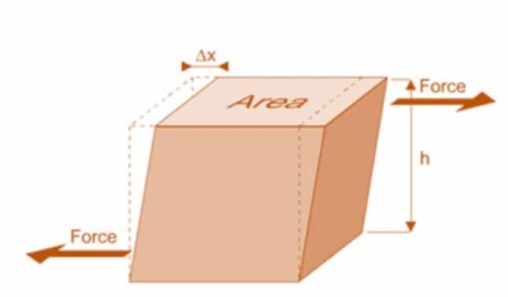
Fig.: Shear Deformation of Body
When a body is subjected to simple tensile stress within its elastic limits then there is a change in the dimensions of the body in the direction of the load as well as in the opposite direction.
When these changed dimensions are divided with their original dimensions, longitudinal strain and lateral strain are obtained.
The ratio of the lateral strain to the longitudinal strain is called Poisson’s ratio.
It is represented by the symbol “µ”. Poisson’s ratio is maximum for an ideal elastic incompressible material and its value is 0.5.
For most of the engineering materials, Poisson’s ratio lies between 0.25 and 0.33. It has no units.
Key takeaways:
- When these changed dimensions are divided with their original dimensions, longitudinal strain and lateral strain are obtained.
- The ratio of the lateral strain to the longitudinal strain is called Poisson’s ratio.
- It is represented by the symbol “µ”. Poisson’s ratio is maximum for an ideal elastic incompressible material and its value is 0.5.
When a body is subjected to mutually perpendicular direct stresses which are alike and equal, within its elastic limits, the ratio of direct stress to the corresponding volumetric strain is found to be constant.
This ratio is called bulk modulus and is represented by letter “K”.
Unit of Bulk modulus is Mpa.

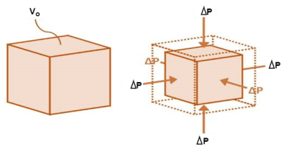
Fig.: Volumetric Change of Body
- The relationship between Young’s modulus (E), rigidity modulus (G) and Poisson’s ratio (µ) is expressed as:

- The relationship between Young’s modulus (E), bulk modulus (K) and Poisson’s ratio (µ) is expressed as:

1. Young’s modulus can be expressed in terms of bulk modulus (K) and rigidity modulus (G) as:

- Poisson’s ratio can be expressed in terms of bulk modulus (K) and rigidity modulus (G) as:

Numerical:
Q. A bar of cross-section 8mm×8mm is subjected axial pull of 10kN. The lateral dimensions of the bar are found to be reduced by 2× . Find Poisson’s ratio and modulus of elasticity assuming
Given:


To find: and E
Lateral strain 
Lateral strain 
Stress 
Modulus elasticity 
Using relation


Q. A bar of 25mm diameter, is objected to a pull of 40kN. The measured extension on gauge length of 200 mm is 0,085 mm and change in diameter is 0.003 mm. Calculate the Poisson’s ratio and the three values of the module.
Given:

To find and K
Area 


Poisson’s ratio 

Young’s modulus 


Shear modulus 

Q. A 50mm square steel bar is subjected to an axial tensile load of 250 kN. Determine the decrease in the lateral dimension if E=200 GPa and v=0.30.
Given:
Side a=50mmP=250kN=250× ,=0.3
,=0.3
E=200 GPa=200× MPa
MPa
To find: δa
Stress 
Linear strain 
Change in lateral dimension


Q. A bar of diameter 20 mm and length 200, extends by a length of 0.4 mm upon application of a load P. What is the value of P if the young’s modulus of the material is known to be 2× N/m
N/m . What is the change in the cross sectional area of the bar at this stage if the Poisson’s ratio is 0.28. If an extension of the bar were to be limited to 0.3mm under same load P, what should be the diameter of the bar?
Given:
To find
(i) P for δL=0.4(ii) P for δL=0.28 (iii) Diameter d for δL=0.3
Case I: Applied load P for δL=0.4mm
Given d=20mm L=200mmδL=-.4mmE=2× N/m
N/m
Area 
Axial load P 


Case II: Change in cross-sectional are if =0.28
Linear strain
Lateral strain 
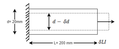


Reduced diameter 

Case III: Diameter of the bar if δL=0.3mm


Q. A circular rod of 120 mm diameter and 500 mm long is subjected to a tensile load of 1000kN. Determine Modulus of Rigidity, Bulk Modulus and change in volume. Assume Poisson’s ratio 0.3 and 
Given:
Diameter
Length
Tensile load
Poisson’s Ratio = 0.3
Modulus of Elasticity 
To find: G,K, dv
Using relation 


Now, 

Change in Volume


Q. A cylindrical piece of steel 80 mm diameter and 120 mm long compressive force 70kN. Calculate the change in volume of the piece if Bulk modulus is  and Poisson’s ratio is 0.3.
Given:


To find: δV
Modulus of elasticity

Area 
Stress 
Volumetric strain for member subjected uniaxial force


References:
- Timoshenko, S. And Young, D. H., “Elements of Strength of Materials”, DVNC, New York USA.
- Kazmi, S. M. A., “Solid Mechanics” TMH, Delhi, India.
- Hibbeler, R. C. Mechanics of Materials. 6th ed. East Rutherford, NJ: Pearson Prentice Hall, 2004
- Crandall, S. H., N. C. Dahl, and T. J. Lardner. An Introduction to the Mechanics of Solids 2nd ed. New York, NY: McGraw Hill, 1979
- Laboratory Manual of Testing Materials - William Kendrick Hall
- Mechanics of Materials - Ferdinand P. Beer, E. Russel Johnston Jr., John T. DEwolf – TMH 2002.