Unit – 3
Shear force and bending moment diagrams
1. Shear force:
The shear force at the cross section of a beam is defined as the algebraic sum of all the unbalanced vertical forces either left or right of the section.
SF = (∑ Fy)L = (∑ Fy) R
This is special to compression, which takes place while the two opposing forces are pushing into every different on the identical point (i.e. they may be not offset), ensuing in compressive stress.
When a structural member experiences failure through shear, components of it are driven in special directions, for example, while a piece of paper is reduce through scissors.
A shear force is a force implemented perpendicular to a surface, in competition to an offset force appearing within side the contrary direction
Sign convention for shear force:
An upward force to the left of section or downward force to the right of a section will be considered as a positive shear force.
When the force is downward to the left side of section and upward on the right of a section, will be considered as a negative shear force.
2. Bending Moment:
The bending moment at any cross section of the beam is defined as the algebraic sum of moment of all the forces either left or right of the section.
BM= (∑MF)L = (∑MF)R
Bending moment is the response brought about in a structural detail whilst an outside pressure or second is carried out to the detail, inflicting the detail to bend
The inner response hundreds in a cross-segment of the structural detail may be resolved into a resultant pressure and a resultant couple. For equilibrium, the instant created via way of means of outside forces (and outside moments) should be balanced via way of means of the couple brought about via way of means of the inner hundreds. The resultant inner couple is known as the bending moment at the same time as the resultant inner pressure is known as the shear pressure.
The bending moment at a segment C because of a unit load at X can further be received via way of means of direct equilibrium. The form of bending second diagram can be triangular with the peal cost going on under the unit load location. For this reason the bending second at any segment because of a un it load is most whilst the burden acts precisely on the segment below consideration.
If clockwise bending moments are taken as terrible (negative), then a terrible bending moment inside an detail will cause "hogging", and a superb ( positive) second will cause "sagging". It is consequently clean that a factor of 0 bending moment inside a beam is a factor of contra flexure—that is, the factor of transition from hogging to sagging or vice versa.
Sign convention of bending moment
Sagging bending moment: when clockwise moment on the left of the section or anticlockwise moment on the right of the section is considered as positive B.M. Or sagging B.M.
Hogging bending moment: when the anticlockwise moment on the left of the section or clockwise moment on the right of the section is considered as negative or hogging B.M.
Key takeaways:
- An upward force to the left of section or downward force to the right of a section will be considered as a positive shear force.
- Sagging bending moment: when clockwise moment on the left of the section or anticlockwise moment on the right of the section is considered as positive B.M. Or sagging B.M.
- When the force is downward to the left side of section and upward on the right of a section, will be considered as a negative shear force.
The 5 forms of hundreds which can act on a shape are Tension or anxiety, compression, shear, bending and torsion.
- Tension:
Two pulling (opposing) forces that reach an item attempting to drag it apart (for example, pulling on a rope, a vehicle towing some other vehicle with a chain – the rope and the chain are in anxiety or are "being subjected to a tensile load").
2. Compression:
Two pushing (opposing) forces that squeeze an item looking to compress it (for example, status on a soda can, squeezing a bit of timber in a vise – each the can and the timber are in compression or are "being subjected to a compressive load").
3. Shear:
Two pushing or pulling adjoining forces, appearing near collectively however now no longer at once opposing every different. A shearing load cuts or rips an item via way of means of sliding its molecules aside sideways (for example, pruning shears reducing thru a department, paper-cutter reducing paper - the department and paper are "subjected to a shear loading").
A drawing of a beam with a hundred and twenty lbs of pressure at the beam, now no longer pretty opposing every different. Inside, molecules keep onto every different to face up to being slid aside.
A Moment of a Force Understanding a second of a pressure is prime to information the ultimate kinds of loads. A second is a "turning pressure" because of a pressure appearing on an item at far from a set point. Consider the diving board caricature in The heavier the person (pressure), and the farther they stroll out at the board (distance), the extra the "turning pressure," which acts at the concrete foundation (constant point).
The pressure (F) produces a second or "turning pressure" (M) that attempts to rotate the diving board round a set point (A).
In this case, the instant bends the diving board. The more potent the pressure, and the more the gap at which it acts, the bigger the instant or "turning pressure" it'll produce. A second or "turning pressure" (M) is calculated via way of means of multiplying a pressure (F) via way of means of its second arm (d). The second arm is the gap at which the pressure is applied, taken from the constant point:

If a force measured in Newton’s is accelerated with the aid of using a distance in meters, then the devices for the instant are N-m (read "Newton-meters"). If the pressure is measured in kilos and multiply with the aid of using a distance in inches, then the devices are be lb-in (read "pound-inches").
Units for moments may be any pressure unit accelerated with the aid of using any distance unit.
4. Bending:
When a second or "turning pressure" is carried out to a structural member this is constant on each ends, along with a pole beam, making it deflect or bend. A second that reasons bending is known as a bending second. Bending produces anxiety and compression interior a beam or a pole, inflicting it to "smile." The molecules at the pinnacle of the smile get squeezed together, whilst the molecules on the lowest of the smile get stretched out. A beam or pole in bending will fail in anxiety (spoil at the aspect this is being pulled apart) (for example, a shelf in a bookcase, and the sooner diving board scenario).
5. Torsion (Twisting):
Created while a second or "turning force" is carried out to a structural member (or piece of material) making it deflect at an angle (twist). A second that reasons twisting is referred to as a twisting or torsion second. Torsion produces shear stresses within the material. A beam in torsion will fail in shear; the twisting motion reasons the molecules to be slid aside sideways (for example, a pole with a signal striking off one side).
Key takeaways:
- Two pulling (opposing) forces that reach an item attempting to drag it apart
- Two pushing (opposing) forces that squeeze an item looking to compress it (for example, status on a soda can, squeezing a bit of timber in a vise – each the can and the timber are in compression or are "being subjected to a compressive load").
- Two pushing or pulling adjoining forces, appearing near collectively however now no longer at once opposing every different.
A structural assist is part of a constructing or shape that gives the vital stiffness and power a good way to withstand the inner forces (vertical forces of gravity and lateral forces because of wind and earthquakes) and manual them properly to the ground. External loads (movements of different bodies) that act on homes motive inner forces (forces and couples with the aid of using the relaxation of the shape) in constructing assist structures.
Supports may be both on the stop and at any intermediate factor alongside a structural member or a constituent a part of a constructing and they're known as connections, joints or restraints.
Building assist structures, irrespective of what substances are used, should deliver correct and secure results. A shape relies upon much less at the weight and stiffness of a cloth and extra on its geometry for stability.
Whatever the circumstance is, a selected tension is vital for connection designs. The assist connection kind has consequences at the load bearing ability of every element, which makes up a structural system. Each assist circumstance affects the behavior of the factors and therefore, the system.
Structures may be both Horizontal-span assist systems (ground and roof structures) and Vertical constructing shape systems (walls, frames, cores, etc.)[3] Contents
There are 5 simple idealized guide shape types, classified with the aid of using the varieties of deflection they constrain: curler or Roller, pinned, fixed, hanger and easy guide.
- Roller supports
A roller support lets in thermal growth and contraction of the span and stops harm on different structural participants together with a pinned guide. The normal software of curler helps is in massive bridges. In civil engineering, curler helps may be visible at one cease of a bridge. A roller support can't save you translational actions in horizontal or lateral instructions and any rotational motion however prevents vertical translations.
Its response pressure is a unmarried linear pressure perpendicular to, and away from, the surface (upward or downward). This guide kind is believed to be able to resisting ordinary displacement. It may be rubber bearings, rocker or a fixed of gears permitting a restricted quantity of lateral motion. A shape on curler skates, for example, stays in area as lengthy because it have to simplest guide itself. As quickly as lateral load pushes at the shape, a shape on curler skates will roll away in reaction to the pressure.
2. Pinned support
A pinned support attaches the simplest net of a beam to a girder known as a shear connection. The guide can exert a pressure on a member appearing in any course and save you translational actions, or relative displacement of the member-results in all instructions however can't save you any rotational actions.
Its response forces are unmarried linear forces of unknown course or horizontal and vertical forces that are additives of the single pressure of unknown course.
A pinned support is much like a human elbow. It may be prolonged and flexed (rotation), however you can't circulate your forearm left to right (translation). One gain of pinned helps isn't always having inner second forces and simplest their axial pressure gambling a huge position in designing them. However, a unmarried pinned guide can't absolutely restrain a shape. At least helps are had to withstand the second. Applying in trusses is one common manner we will use this support.
3. Fixed Support
Rigid or fixed supports hold the angular dating among the joined factors and offer each pressure and second resistance. It exerts forces performing in any course and forestalls all translational moves (horizontal and vertical) in addition to all rotational moves of a member. These helps’ response forces are horizontal and vertical additives of a linear resultant; a second.
It is a inflexible kind of help or connection. The utility of the constant help is useful while we will best use unmarried help, and those maximum extensively used this kind because the best help for a cantilever.
They are not unusual place in beam-to-column connections of second-resisting metallic frames and beam, column and slab connections in concrete frames.
4. Hanger support
A hanger support best exerts a pressure and forestalls a member from performing or translating away within side the course of the hanger.
However, this help can't save you translational motion in all guidelines and any rotational motion. This is one of the best structural paperwork wherein the factors are in natural tension. Structures of this kind variety from easy guyed or stayed systems to big cable-supported bridge and roof systems.
5. Simple support
A simple support is largely in which the structural member rests on an outside shape as in concrete blocks keeping a resting plank of wooden on their tops.
This help is just like curler help in a feel that restrains vertical forces however now no longer horizontal forces. Therefore, it isn't extensively utilized in actual lifestyles systems except the engineer may be positive that the member will now no longer translate.
Key takeaways:
- A roller support lets in thermal growth and contraction of the span and stops harm on different structural participants together with a pinned guide.
- The normal software of curler helps is in massive bridges. In civil engineering, curler helps may be visible at one cease of a bridge.
- A roller support can't save you translational actions in horizontal or lateral instructions and any rotational motion however prevents vertical translations.
If a guide prevents translation of a frame in a given route, a pressure is evolved at the frame in that route. The guide prevents translation in vertical and horizontal instructions and additionally rotation, Hence a pair second is evolved at the frame in that route as well
Support in a shape is a member which enables others member to withstand loads. Different kinds of supports, their reactions and packages for systems and their information is discussed. Supports in a shape transfers the burden to the floor and presents balance to the shape supported on it.
External Supports and Reactions and Applications in a Structure
The helps that are commonly furnished externally without worrying the structural participants are outside helps. Different styles of outside helps are as follows:
- Fixed support
- Pinned support or hinged support.
- Roller support
- Rocker support
- Link support
- Simple support
Fixed Support and Reactions and Applications in a Structure
Fixed helps also are known as inflexible helps. Fixed helps are confined in opposition to each rotation and translation which will face up to any sort of pressure or moment. In structural analysis, there are 3 unknowns to discover for constant guide that could fulfill all of the 3 equations of equilibrium. To offer correct balance to the structure, as a minimum one inflexible guide need to be provided. Beam constant in wall is a superb instance for constant guide.
Pinned Support and Reactions in a Structure
Pinned support or hinged support can resists each vertical and horizontal forces however they can't face up to moment. It method hinged help is restricted in opposition to translation. Using equations of equilibrium, you'll discover the additives of horizontal and vertical forces.
Best instance for hinged help is door leaf which handiest rotates approximately its vertical axis with none horizontal or vertical movement. The rotation of pinned help or hinged help is permitted in handiest one path and is resisted in different path. Hinged helps also are utilized in 3 hinged arched bridges with helps at ends and 0.33 hinge is supplied on the middle of the arch that is known as inner hinge
Key takeaways:
- If a guide prevents translation of a frame in a given route, a pressure is evolved at the frame in that route.
- The guide prevents translation in vertical and horizontal instructions and additionally rotation, Hence a pair second is evolved at the frame in that route as well
- Support in a shape is a member which enables others member to withstand loads. Different kinds of supports, their reactions and packages for systems and their information is discussed.
There is a relation amongst depth of load w, Shear Force F and Bending Moment M.
For the derivation of the relation amongst those three we recollect a definitely supported beam subjected to a uniformly allotted load w(x) for the duration of its period (L)
Re collect a small detail of period dx at a distance of x shape left aid.
Let the shear force and bending second at a segment positioned at a distance of x from the left aid be V and M, respectively, and at a segment x + dx be V + dV and M + dM, respectively.
The overall load acting within side the detail is W dx, acts on the middle of the detail period dx.
Considering the detail is in equilibrium take moments on proper facet of detail.
∑ Mx + dx = ∑ MR = 0
=- (M + dM) + M + V dx + wdx.dx/2 = 0
Neglecting small term wdx.dx/2=0
-dM+ V dx = 0
DM = V dx
DM/dx = V(x)
This relation implies that the primary by-product of the bending second with recognize to the gap is same to the shearing force. Rate of extrude of Bending Moment is same to Shear force.
DM/dx = F(x)
The equation also shows that the slope of the instant diagram at a specific factor is identical to the shear pressure at that identical factor. Shows the subsequent expression:
∆M = ∫ V (x) dx
This states that the alternate in moment equals the region below the shear diagram.
Similarly, the vertical equilibrium within side the element,
∑ Fy = 0
V – w dx – (V+ dV) = 0
DV = -w dx
This relation implies that the primary by-product of the shearing pressure with admire to the space is same to the depth of the allotted load.
Rate of alternate of Shear Force is same to Intensity of loading.
DF/dx = - w(x)
The equation additionally shows that the slope of the shear pressure diagram at a selected factor is same to the depth of load at that equal factor
It additionally shows the following expression:
∆V = ∫ w (x) dx
This equation states that the alternate within side the shear pressure is same to the vicinity be neat the burden diagram.
By taking both relations
DV/dx = - w(x) and
DM/dx = V (x); we get one extra relation
d/dx = -w(x)
The relation implies that the second one by-product of the bending second with admire to the space is same to the depth of the allotted load.
Key takeaways:
- There is a relation amongst depth of load w, Shear Force F and Bending Moment M.
- For the derivation of the relation amongst those three we recollect a definitely supported beam subjected to a uniformly allotted load w(x) for the duration of its period (L)
- Re collect a small detail of period dx at a distance of x shape left aid.
An inflection factor is a factor on a curve at which the signal of the curvature (i.e., the concavity) changes. In case of stable mechanics, it's far a factor at the beam in which curvature changes. And factor of contra flexure is a factor at the bending second diagram of a beam in which it meets x-axis or in which second price is zero.
These are the factors at which the deflection curve of the frame modifications the signal of curvature. In different terms, we will say that the inflection factors are the factors in which the shear pressure modifications its route from +ve to –ve and vice versa.
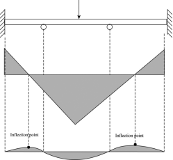
Consider the determine for the shear pressure and bending second diagram and the inflection factors within side the beam.
From the above figure, it is able to be certainly said that the inflection factors are the factors at the bending second diagram at which the shear pressure have 0 value. At the inflection point, the bending second curve modifications of their concavity. To draw the shear pressure and bending second diagram, use the subsequent courting among the unit load w, shear pressure F and the instant M.


To locate the vicinity of zero shear, the reactions are to be envisioned on the start. Find the shear pressure equation and equate it to 0 to get the vicinity of inflection factor. Generally, there are methods, which can be used to locate the factor of 0 shear.
The first technique is wherein the random factor is taken alongside the beam at any distance to estimate the instant courting approximately that factor and equating it to 0. The different technique is primarily based totally on the same triangle idea implemented at the shear pressure diagram. Hence, the factor of inflection is the factor of 0 shear. The factor of the contra flexure is the factor within side the bending second diagram, wherein the importance of bending second is zero.
Key takeaways:
- An inflection factor is a factor on a curve at which the signal of the curvature (i.e., the concavity) changes.
- In case of stable mechanics, it's far a factor at the beam in which curvature changes. And factor of contra flexure is a factor at the bending second diagram of a beam in which it meets x-axis or in which second price is zero.
- These are the factors at which the deflection curves of the frame modifications the signal of curvature.
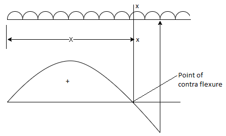
Point of contra flexure
It is the point at which bending moment diagram change its sign generally bending moment at the point is equal to zero. It is definitely occurring in case of overhang beam within support. Point of contra flexure is calculated by equating expression of B.M.
BMXX = 0
1. Bending moment’s diagrams
The bending moment at any cross section of the beam is defined as the algebraic sum of moment of all the forces either left or right of the section.
BM= (∑MF) L = (∑MF) R
Bending moment is the response brought about in a structural detail whilst an outside pressure or second is carried out to the detail, inflicting the detail to bend
The inner response hundreds in a cross-segment of the structural detail may be resolved into a resultant pressure and a resultant couple. For equilibrium, the instant created via way of means of outside forces (and outside moments) should be balanced via way of means of the couple brought about via way of means of the inner hundred. The resultant inner couple is known as the bending moment at the same time as the resultant inner pressure is known as the shear pressure.
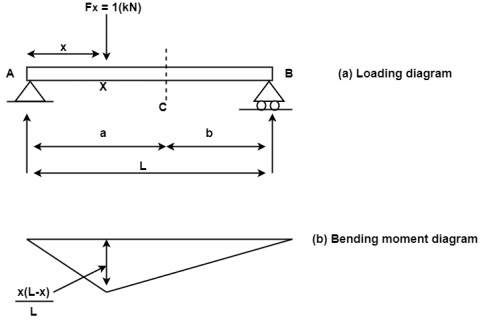
The bending moment at a segment C because of a unit load at X can further be received via way of means of direct equilibrium. The form of bending second diagram can be triangular with the peal cost going on under the unit load location. For this reason, the bending second at any segment because of a un it load is most whilst the burden acts precisely on the segment below consideration.
If clockwise bending moments are taken as terrible (negative), then a terrible bending moment inside a detail will cause "hogging", and a superb (positive) second will cause "sagging". It is consequently clean that a factor of 0 bending moment inside a beam is a factor of contra flexure—that is, the factor of transition from hogging to sagging or vice versa.
Sign convention of bending moment
Sagging bending moment: when clockwise moment on the left of the section or anticlockwise moment on the right of the section is considered as positive B.M. Or sagging B.M.
Hogging bending moment: when the anticlockwise moment on the left of the section or clockwise moment on the right of the section is considered as negative or hogging B.M.
The bending moment obtained analytically are represent by plotting bending moment as ordinate (y- axis) against the position of cross section as abscissa (x- axis) the diagram obtained is called bending moment diagram.
The bending moments are sagging throughout the beam and hence according to our usual sign convention they have positive value.
2. Shear Force diagrams:
The shear force at the cross section of a beam is defined as the algebraic sum of all the unbalanced vertical forces either left or right of the section.
SF = (∑ Fy) L = (∑ Fy) R
This is special to compression, which takes place while the two opposing forces are pushing into every different on the identical point (i.e., they may be not offset), ensuing in compressive stress.
When a structural member experiences failure through shear, components of it are driven in special directions, for example, while a piece of paper is reduced through scissors.
A shear force is a force implemented perpendicular to a surface, in competition to an offset force appearing within side the contrary direction
Sign convention for shear force:
An upward force to the left of section or downward force to the right of a section will be considered as a positive shear force.
When the force is downward to the left side of section and upward on the right of a section, will be considered as a negative shear force.
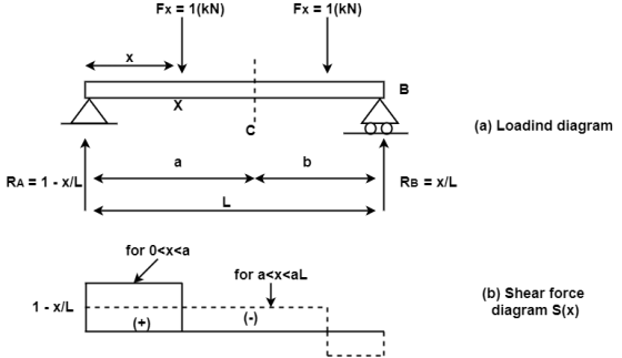
The shear force obtained analytically are representing by plotting shear force as ordinate (y- axis) against the position of cross section as abscissa (x- axis) the diagram obtained is called as shear force diagram.
Key takeaways:
- The bending moment at any cross section of the beam is defined as the algebraic sum of moment of all the forces either left or right of the section.
- BM= (∑MF) L = (∑MF) R
- Bending moment is the response brought about in a structural detail whilst an outside pressure or second is carried out to the detail, inflicting the detail to bend.
When the beam is subjected to a constant bending moment no shear stresses are induced in that portion of beam is called as simple bending or pure bending.
A simply supported beam ABCD subjected to two equal point load w at equal distance ‘a’ from each support.
In this chapter we are considering the beam is subjected to pure bending only. i.e. shear force neglected.
In shear force diagram the shear force between portion BC is zero.
In bending moment diagram the bending moment between portions BC is constant. The portion BC is said to be under pure bending.


Assumptions
1. The material of beam is homogeneous and isotropic. (isotropic means having the properties same in all direction.)
2. The beam is straight before loading.
3. The beam is uniform cross section throughout its length.
4. Transverse section which is plane before loading remains plan even after loading.
5. The material is elastic and hooks law is applicable.
6. The effect of shear is neglected therefore the analysis is meant for pure bending.
7. The modulus of elasticity E has same value in tension and compression.
8. Each layer is free to expand or compact having no influence in the neighboring layers for their extraction and contraction.
9. The beam is initially straight and all longitudinal filaments bend into circular area with a common center of curvature.
Key takeaways:
1. The material of beam is homogeneous and isotropic. (isotropic means having the properties same in all direction.)
2. The beam is straight before loading.
3. The beam is uniform cross section throughout its length.
1. Determination of bending stresses – section modulus of rectangular:
Example1]
Maximum bending moment of simply supported beam of 10 KNM The cross section of the beam is as shown in fig .find the maximum bending stress in tension and compression.
Diagram:
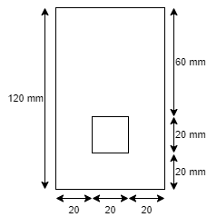
Solution
Given:
M = 10 KNM = 10 x 104 N.mm
Beam = simply supported
To find: 
Strep 1) Position of neutral axis

A1 = 60 x 120 = 7200 mm2
A2 = 20x 20 = 400 mm2
y1 = 120/2 = 60 mm
y2 = 20/2 + 20 = 30 mm


Since, the beam is simply supported,
yt = y = 61.76mm
yc = 120 –y -= 120 – 61.76 = 58.24 mm
Step 2) moment of inertia
Ixx = Ixx1 – Ixx2
[IG1 + A1h12] – [IG2 + A2h22]

= 8.662 x 10⁶ – o.4168 x 106
= 8.245 x 106 mm4
2. Determination of bending stresses – section modulus of circular:
Example:
A beam is circular section of diameter d and length L is a simply supported at ends carries central point load W- 2KN L= 4m what should be the value of diameter d so that maximum stresses in beam does not exceed 80 Mpa
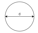
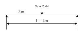
Solution:
Given:
L= 4 m
W= 2 KN
To find:
Bending moment
M= WL/4
= 2x 4 /4
= 2 KN.m
Using bending moment formula


3. Determination of bending stresses – section modulus of I angle:
Example1]
A beam of span 4 m carries a udl 15 KN/M the cross section of the beam as shown in fig. Find maximum stress induced bending stress diagram.
Diagram:
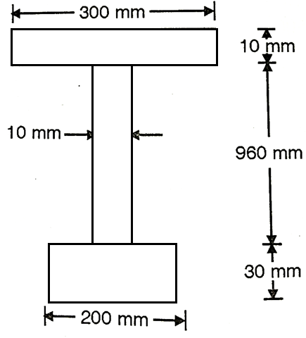
Solution:
Given:
L = 4m
W = 15 KN/M
To find: 
Maximum bending moments


Position neutral axis:

A1 = 200 x 30 = 6000 mm2
A2 = 10 x 960 = 9600 mm2
A3 = 300 x 10 = 3000mm2
y1 = 30/2 = 15 mm
y2 = 960/2 +30 = 510 mm
y3 = 10/2 + 960+30 = 995 mm


Moment of inertia
I = Ixx1+ Ixx2+Ixx3
= [Ix1+A1h12] + [Ix2+A2h22] + [Ix3+A3h32]

= 2.7896 x 103 mm4
Depth of neutral axis from top
yc = 1000-y1 = 1000-428.55
Ymax. 571.45mm
Maximum bending stress


The maximum stress induce in the bean section is 6.15 mpa
4. Determination of bending stresses – section modulus of T angle
Example 1]
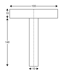
A simply supported beam of 5 m span carries uniformly distributed load of 2 KN/M over span cross section of the beam is shown in fig. Find maximum bending stress induced in beam
Diagram
Solution:
Given:
L =5m
Udl w = 2 KN/M
To find:
Position of neutral axis
A1 = 140 x 10 = 1400 mm2
A2 = 100x10 = 1000mm2
y1 = 140/2 = 70mm
y2 = 140+10/2 = 145mm


y= 101.25mm
Moment of Inertia
I = Ixx1 + Ixx2

= 5.576x104 mm4
Find moment
wL2/2 = 2x52/2 = 6.25KN-m
Since, the beam is simply supported tension induced below N.A
y= yt= 101.25mm
Yc= 150-101.25= 48.75 mm
Maximum bending stress using flexure formula


The maximum bending stress induced in the beam is 113.5 N/mm2
5. Determination of bending stresses – section modulus of channel section:
Example:
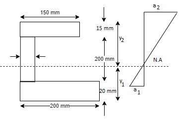
A CI beam of c section with top flange 150 mm x 15mm bottom flange 200mmx20mm and web 15mmx 200 mm is supported over a span of them it the permissible stresses are 120 mpa compression what udl can be safety applied on beam. What will be tensile stress in the beam
Solution
Given:

To find :
Safe udl w and tensile stress
Position of neutral axis
A1 = 200 x 20 = 4000 mm2
A2 = 200 x 15 = 3000 mm2
A3 = 15 x 150 = 2250 mm2
y1 = 10 mm
y2= 120 mm
y3 = 227.5 mm

Moment of inertia
Ixx= Ixx1+Ixx2
= 
Ixx = 80.33 x 106 mm4
Position of extreme fiber from NA
y= yt = 98.5 mm
Yc = 235-98.5 = 136.5 mm
Bending formula


Maximum bending moment = wl2/8 = 15.7 kN/m
Tensile stress:


1. Shear stresses:
The shear force at the cross section of a beam is defined as the algebraic sum of all the unbalanced vertical forces either left or right of the section.
SF = (∑ Fy)L = (∑ Fy) R
Sign convention for shear force:
An upward force to the left of section or downward force to the right of a section will be considered as a positive shear force.
When the force is downward to the left side of section and upward on the right of a section, will be considered as a negative shear force.
2. Derivation of formula
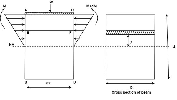
Consider a small portion ABCD of length dx of a beam with bending moment varying from m to m=dm due to udl over its length dx
The distribution of compressive stresses due to bending moment shown in fig
Let
M = bending moment at AB
M + dM = bending moment at CD
F = shear force at AB
F+ dF = shear force at CD
Consider element strip EF at a distance y from the neutral axis as shown in fig.
Let
σ = bending stress across AB at a distance y from neutral axis
σ + d σ = bending stress across
I = moment of inertia
By using flexural formula

On face AB, 
On face CD, 
Face acting across AB 
Similarly, force acting across CD, 
Net unbalanced force on the strip

The load unbalanced force F above neutral axis can be found out by integrating from 0 to d/2


But ∫ y x dA= first moment of area under consideration from neutral axis= A
F = dM/ I x Ax
This unbalanced force is balanced by a shearing stress 𝜏 acting along the length dx and width b,
Shear stress = shear force/ shear area


But 

Where,
S = shear force at the section under consideration
A = area above or below the layer under consideration
 = distance of centroid of area under consideration from neutral axis
b = width at the layer under consideration
I = moment of inertia of the section.
Key takeaway:
- The shear force at the cross section of a beam is defined as the algebraic sum of all the unbalanced vertical forces either left or right of the section.
- An upward force to the left of section or downward force to the right of a section will be considered as a positive shear force.
- When the force is downward to the left side of section and upward on the right of a section, will be considered as a negative shear force.
Distribution of normal stress
A ordinary strain is a strain that takes place whilst a member is loaded through an axial pressure. The cost of the ordinary pressure for any prismatic segment is without a doubt the pressure divided through the go sectional area. A ordinary strain will arise whilst a member is located in anxiety or compression
Distribution of shear stress:
Any kind of masses can result in kinds of pressure. The stresses are everyday pressure and shear pressure.
The distribution of shearing pressure at the cross-phase of the beam represents a parabolic curve in which the most shearing pressure takes place on the impartial axis of the beam
1. Shear stress distribution over a circular section:
Consider a circular section of diameter d as shown in fig.
Diagram
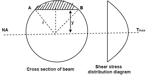
The shear stress on a layer AB at a distance is given as,

Width of strip AB in a circular section

Where, r= radius of circular section
Area of shaded strip =
Moment of area about neutral axis =
The moment of whole shaded area about neutral axis

But 

Again, 
Squaring both side
2b db = 4(-2y) dy

Substituting the value of y.dy in equation (i)

We know that, when y= r. And b = 0
The limit of integration may be changed from y to r, from b to 0 in equation (i)


Now substituting Ay in shear stress formula


Observations from above equation
From Equation (iii) shear stress 𝜏 increases as y decreases
At y = 𝜏 𝜏 = 0
At y = 0 𝜏 is maximum

Put r= d/2

Put I = 𝛑/64 d4


Therefore,


2. Shear stress distribution over a rectangular section:
Consider a beam of a rectangular section of width b and depth d as shown in fig.

Shear stress at any layer CD of beam at a distance y from the neutral axis

Where,
S = shear force at the section
A = Area of beam above y
 = Distance of centroid of shaded area from neutral axis
I = Moment of inertia of the section
b = Width of section CD
Area of shaded portion 
Distance of centroid of area from neutral axis


Moment of inertia 
Shear stress at any layer CD


From above equation we can observe that,
𝜏 increases as y decrease
Variation of 𝜏 is parabolic as the equation in of second degree
When y = d/2, 𝜏 = 0
When y= 0, 𝜏 is maximum
The variation of shear stress across the depth of the beam is parabolic.
Shear Stress
At top and bottom, y= d/2 
At neutral axis, y= 0


Where

Example 1]
A beam of rectangular section is 100 mm wide and 200 mm deep. If the section is subjected to a maximum shear force of 10000 N. Find the maximum shear stress. Also draw the shear stress distribution across the section.
Solution:
Given: b= 100 mm, d = 200 mm, S = 10000 N
To find: 
Moment of inertia


Maximum shear stress


Key takeaways:
- A ordinary strain is a strain that takes place whilst a member is loaded through an axial pressure.
- The cost of the ordinary pressure for any prismatic segment is without a doubt the pressure divided through the go sectional area.
- A ordinary strain will arise whilst a member is located in anxiety or compression
Composite Beams: Composite beams are created from a couple of cloth to growth stiffness or strength (or to lessen cost).
Similar to axially loaded two-cloth beams, while a beam is subjected to a moment, the pressure continues to be continuous, however the strain is discontinuous.
Two-material Composite Beams -Axial Load Strain and Stress in Two-material Composite Beam undergoing Axial Loading The best loading in a composite beam is axial loading. The stress is non-stop throughout the beam pass segment however the pressure is discontinuous as proven within side the diagram on the left. When axially loaded, the everyday lines are identical because the substances are rigidly attached. From Hooke's law, this gives


Eliminating  gives
gives

Total load p must be

Combined the previous two equation


Two-material Composite Beams - Moment Load Strain and Stress in Two-material Composite Beam undergoing Moment Loading Similar to axially loaded two-material beams, whilst a beam is subjected to a moment, the pressure continues to be continuous, however the pressure is discontinuous.
Where the pressure and pressure in axial loading is constant, the bending pressure and pressure is a linear feature via the thickness for every cloth segment as proven on the left. The bending pressure equations require the place of the impartial axis. For non-composite beams, the impartial axis (NA) is the centroid of the move segment. This isn't the case for composite beams and is one of the important problems in fixing for the bending pressure.
Thus, step one in calculating bending pressure is finding the NA. Then the bending pressure equation, My/I, may be used to locate the pressure in every cloth. There could be a separate equation for the bending pressure in every cloth segment.
Key takeaways:
- Composite Beams: Composite beams are created from a couple of cloth to growth stiffness or strength (or to lessen cost).
- Similar to axially loaded two-cloth beams, while a beam is subjected to a moment, the pressure continues to be continuous, however the strain is discontinuous.
- Two-material Composite Beams -Axial Load Strain and Stress in Two-material Composite Beam undergoing Axial Loading The best loading in a composite beam is axial loading.
References:
- Timoshenko, S. And Young, D. H., “Elements of Strength of Materials”, DVNC, New York USA.
- Kazmi, S. M. A., “Solid Mechanics” TMH, Delhi, India.
- Hibbeler, R. C. Mechanics of Materials. 6th ed. East Rutherford, NJ: Pearson Prentice Hall, 2004
- Crandall, S. H., N. C. Dahl, and T. J. Lardner. An Introduction to the Mechanics of Solids 2nd ed. New York, NY: McGraw Hill, 1979
- Laboratory Manual of Testing Materials - William Kendrick Hall
- Mechanics of Materials - Ferdinand P. Beer, E. Russel Jhonston Jr., John T. DEwolf – TMH 2002.