Unit – 4
Deflection of Beams and Theory of Columns
1. Determinate Beam: The determinate beam is that the beam in which unknown support reactions can be calculated by using static equilibrium equations only.
Example: Simply supported beams, cantilever beams, single and double overhanging beams.
2. Slope and Deflection of beams
Macaulay’s method
(Double ∫∫ method)
(Integration)
3. Basics:
1. Elastic curve: Deformed shape of beam is called as elastic curve.
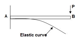
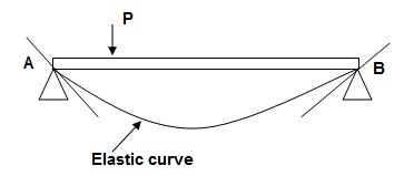
2. Slope: Angle made by tangent joint to the elastic curve with x-axis is called as slope.
3. Deflection: Translation of cross-section normal to the longitudinal axes of member is called as deflection.
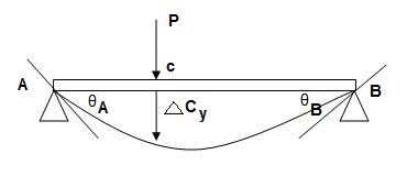
4. Reference System:
Left end of beam is taken as origin and reference system is as below.

5. Sign conventions:
(A). Slope
ϴ + dy/dx = Anticlockwise rotation of tangent
Dy/dx = clockwise rotation of tangent
(B) Deflection
+y = upward Deflection
-y = downward Deflection
6. Flexural Rigidity = (EI)
Product of young modulus of elasticity and moment of inertia of cross-section is called as Flexural rigidity (FI).
Unit: KN.m2
Note: Slope and deflections are inversely proportional to FI.
7. Boundary conditions:
These are nothing but support conditions.
i) At fixed end:

dy/dx = 0
y = 0
Ii) At hinged and roller end
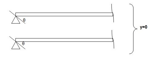
Q. Write boundary conditions for following beams
1)
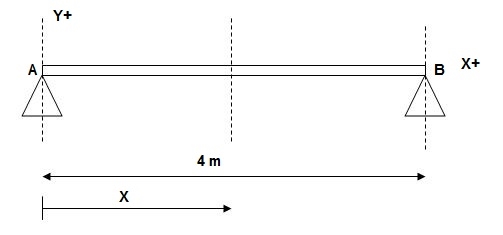
At x = 0; yA = 0
x = 4m; yB = 0
2)
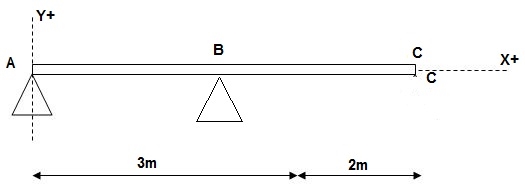
At x = 0; yA = 0
x = 3m; yB = 0
3)
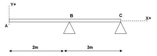
At x = 2m; yB = 0
At x = 5m; yC = 0
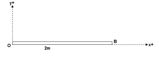
At x = 0; {dy/dx}A = 0
X = 0; yA = 0
8. Concept of Macaulay’s Method
We have,
M/I = 6/y = E/R
Where; R = Radius of curvature
= {1 + (dy/dx)2 }3/2 / d2y/dx2
For beams values of dy/dx are very small
R ≈ 1/d2y/dx2
M/I = E/R, E/1/d2y/dx2 = Ed2y/1 x dx2
M/I = Ex (d2y/dx2)
M = EI.d2y/dx2 = - - - - F(x) = BM eqn
ϴ = EI (dy/dx) = ----------- +c1 = slope eqn
Deflection EI(y) = --------- + C1(x) + C2 = Defneqn
(Eqn. Of elastic curve)
9. B.M equations:
Note:
For writing BM equation always consider section at a distance x from origin, placed in right extreme zone.
- Case 1
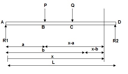
EI (d2y/dx2) = BMx = R1(x) | - P(x-a) | - Q(x-b)
- Case 2
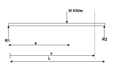
EI (d2y/dx2) = BMx = R1x | - w(x-a)2/2
EI (d2y/dx2) = BMx = R1(x) | - wx2/2 | + w(x-a)2/2
- Case 3:
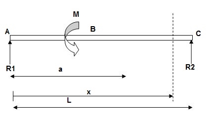
EI(d2y/dx2) = BMx = R1(x) | - M(x-a)
10. Procedure for Macaulay’s method:
i). Find support reactions
Ii). Equations
Iii). Find constants C1& C2 using boundary conditions
IV). Find slope &deflection
Notes:
1] Value of FI shall be substituted at the end of calculation in KN m2.
2] Answer for slope will be in radians and deflection in meter (m).
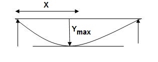
3] For simply supported beam at a section where deflection is maximum, slope is zero.
Example:
1]. Given:
E = 200 GPa = 200 x 103MPa / N/mm2 = 200 KN/mm2
I = 3 x 108 mm4
EI = 200 x 3 x 108 KNmm2
EI = 600 x 102 KNm2
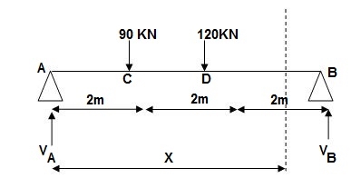
Reactions,
∑MA = VB(6) – 90 x 2 – 120(4) = 0
VB = 660/6
VB = 110 KN
∑Fy = VA + VB – 90 – 120 = 0
VA = -110 +90+120
VA = 100 KN
∑Fx = HA = 0
EI (d2y/dx2) = 100(x) | - 90(x-2) | -120(x-4) ---(1)
EI (dy/dx) = C1 + 100x2/2 | - 90(x-2)2/2 | -120(x-4)2/2 ---(2)
EI(y) = C1(x) + C2 + 100x3/6 | - 90(x-2)3/6 | -120(x-4)3/6 ---(3)
Boundary conditions:
At x=0 | yA = 0, put in (3)
C2 = 0
At x = 6m, yB = 0, put in (3)
6C1 + 100 x 36 – 90 x (4)3/6 – 120 x 23/6 = 0
6C1 + 3600 – 960 – 160 = 0
6C1 = -2480
C1 = (-) 413.33
Slope & Deflection:
X = 0, in (2)
(dy/dx)A = (-) 413.33/EI = (-)4133.33/600 x 102
 = 6.88 x 10⁻³ rad( )
X = 6m in (2),
EI(dy/dx)B = (-)413.33 + 100(6)2/2 – 90(4)2/2 – 120 x (2)2/2
= - 413.33 + 1800 – 720 – 240 = 426.67
 (dy/dx)B = 7.11 x 10⁻³rad( )
X = 2m in (3),
Yc = -413.33 x 2 + 100 x 23/6
= - 826.66 + 133.33
= -693.22/EI = -693.32/600 x 102 = -11.55
 Yc = -11.55 mm( )
X = 4m in (3)
yD = -413.33 x 4 + 100 x 43/6 – 90 x 23/6
= -706.6/EI = -706.6/600 x 102
= - 11.77 mm
 yD = 11.77 mm( )
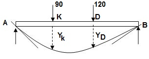
For maximum deflection
Let X > 2m
< 4m - zone CD
EI(dy/dx)CD = - 413.33 + 100/2x2 – 90(x-2)2/2 = 0
-413.33 + 50 x2 – 45(x-2)2 = 0
-413.33 + 50x2 – 45(x2-4x+4) = 0
-413.33 + 5x2 + 180x – 180 = 0
5x2 + 180x – 593.33 = 0
X = 3.03 >2m
<4m
Assumption is correct.
X = 3.03m in (3)
Ymax = -413.33 x 3.03 + 100(3.03)3/6 – 90 x (3.03-2)3/6
= -1252.38 + 463.63 – 16.39
= - 805.14/EI
2]. Given:
EI = 4 x 10⁴ Kn.m2
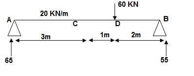
Reactions:
∑MA = 0
VB x 6 – 20 x 3 x x 1.5 – 60 x 4 = 0
VB = 55KN
∑Fy = 0
VA + VB – 60 – 20 x 3 = 0
VA = 65 KN
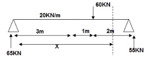
EI (d2y/dx2) = 65 x x | - 20 x x2/2 | + 20 x (x-3)2/2 | - 60(x - -(1)
EI {dy/dx} = C1 + 65x2/2 | - 20 x x3/6 | + 20(x - 3)3/6 | - 60(x - 4)2/2 - - (2)
EI(y) = C1(x) + C2 + 65x3/6 | - 20 x x4/24 | + 20(x-3)4/24 | -60(x-4)3/6 --(3)
Boundary conditions:
At x=0, yA = 0, put in (3)
C2 = 0
X = 6m, yB = 0, put in 3
C1 x 6 + 65 x 62 – 20 x 63/4 + 20 x 34/24 – 60 x 23/6 = 0
C1 = -207.91
Slope & deflection:
X = 3m in (2)
(dy/dx)c = -207.91 + 65 x 32/2 – 20 x 33/6 = -5.41/EI
= -1.35 x 10⁻⁴
 (dy/dx)c = 1.35 x 10⁻⁴ rad( )
X = 3m in 3
yC = -207.9 x (3) + 65 x (3)3/6 – 20 x 34/24 – 398/EI
= - 9.967 x 10-3
= -9.967mm
 yC = 9.967 mm( )
x = 4m in (3)
yD = -207.9 x 4 + 65 x 43/6 – 20 x 43/24 + 20/24
= - 350.7/EI
 = 8.76 mm ( )
3]. Given:
EI = 32.5 x 10³ Kn.m2

Reactions:
∑MA = 0
VB (5) – 45 x 3 x 1.5 + 30 = 0
VB = 34.5 KN
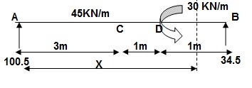
EI {d2y/dx2} = 100.5 x x – 45x2/2 | + 45 x (x-3)2/2 | -30(x-4)0 -- (1)
EI {dy/dx} = C1 + 100.5x2/2 – 45x3/6 | + 45 x (x-3)3/6 | - 30(x-4) --(2)
EI(y) = C1(x) + C2 + 100.5x3/6 – 45x4/24 | + 45 x (x-3)4/24 | - 3(x-4)2/2 --(3)
Boundary conditions:
At x=0; yA = 0 put in eqn3
C2 = 0
At x=5; yB = 0
5C1 + 100.5 x 53/6 – 45(5)4/24 + 45(2)4/24 – 30/2 = 0
C1 = (-) 187.375
Slope &Deflection:
X=3m in (2)
(dy/dx)c = -187.375 + 100.5 x 32/2 – 45(3)3/6
= 62.375/32.5 x 103
 (dy/dx)c = 1.919 rad( )
X = 3m in (3)
yC = -187.375 x 3 + 100.5 x 33/6 – 45 x 34/24
= - 261.75/32.5 x 103
= - 8.053mm
 yC = 8.053mm( )
x = 4m in (3)
yD = -187.375 x 4 + 100.5 x (4)3/6 – 45 x (4)4/24 + 45/24
= - 155.625/32.5 x 103
= - 4.78 mm
 yD = 4.78 mm( )
The reason of calculating deflection in beam is to decide the vertical intensity of its sag from preliminary horizontal (longitudinal) axis of beam.
The slope is the attitude of beam axis between preliminary function and very last function after deflection.
Deflection of beam controls the powerful duration to intensity ratio of beam.
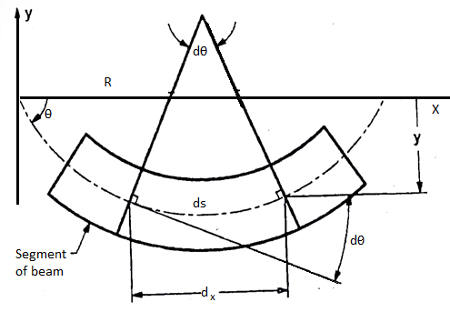
Consider a simply a supported straight beam subjected to transverse loading. It will deflect about its original axis as shown in fig. The deflected axis of beam is called elastic curve which bends into an arc of a circle with radius of curvature R
The elastic curve is very flat and its slope at any point is very small
Slope tan
As slope is very small
Neglect tan,

Diagram:
Differentiate w.r.t. x

From fig. 
Where R is radius of curvature for arc length ds

From flexural bending formula


From above equation


Where EI – is the flexural rigidity of the beam
Is above equation is known as differential equation of the elastic curve of a beam.
However, dx/dy is very small is square is still smaller compared to unity
Integrating equation

Slope deflection
(As  )
)
Again integrated w. r. t. x

Deflection equation where c1 and c2 are the constant in integration which can be evaluate by using support boundary equation
Moment area method
Moment area method is used to determine the slope and deflection at a point in determinate structure and indeterminate structures.
Theorems of moment are suggested by Mohr’s and thus these theorems are called as Mohr’s theorem there are two theorem which are explained
First theorem:
The angle between the tangent drawn at two-point B and Aon the deflected curve of a beam is equal to the area under the bending moment diagram between two-point A and B divided by EI
Proof:
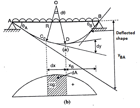
Consider a beam is shown in fig. Subjected to arbitrary load. The deflected shape and BMD of a beam as shown in fig. Respectively
Consider two points C and D at a elements dx on the beam.
The relation between the radius of curvature and BM for any such section is given by


Where negative sign is used with  since
since  decreases with increases in x from a positive maximum value at x=0 to a negative minimum value at x= L
For whole elastic curve
Diagram:
Integrated equation

Where, dA= Area of BMD between point C and D
Change of slope between point B and A
= Area of BMD between B and A / EI
This proves first theorem.
Second Theorem:
Statement:
If A and B are two points on the deflected shape of a beam the vertical distance of point B from the tangent drawn to the elastic curve at point A is equal to moment of area of BMD between point A and B about vertical line from point B divided by EI
Proof:
Consider the distance dy along the vertical line through point B as shown in fig is nearly equal to dt = -XB.d
Integrating equation, we get the vertical distance yBA between the point B and the tangent from point A on the deflected beam

yBA = moment of BMD between A and B at B/ EI
Proved
Key takeaways:
- Moment area method is used to determine the slope and deflection at a point in determinate structure and indeterminate structures.
- Theorems of moment are suggested by Mohr’s and thus these theorems are called as Mohr’s theorem there are two theorem which are explained
- The angle between the tangent drawn at two-point B and Aon the deflected curve of a beam is equal to the area under the bending moment diagram between two-point A and B divided by EI
Column is a compression member the effective length of which exceeds three times the least lateral dimension.
There are three types of columns as per clause 25.1.2 of IS 456-2000
- Pedestal
- Short column
- Long column
- Pedestal
If the length of a column is less than three times its least lateral dimension lex/D<3 or ley/b<3 it is called a pedestal. The other horizontal dimension D shall not exceed four times of b.
2. Short column
If both the slenderness ratio lex/D and ley/b < 12, the column is a short column
3. Long column
If for a column lex/D and ley/b>12, it is a slender column in respect of major or minor axis resp.
If both slenderness ratio are greater than 12, it is slender column in respect of both axes.
Here,
Lex= Effective length of column in respect of the major axis
D= Depth in respect of the major axis
Ley = Effective length of column in respect of minor axis
b= width of the member
According to nature of failure –short, medium and long columns
Short column –whose period is so associated with its c/s location that failure takes place specially because of direct compressive pressure simplest and the position of bending pressure is negligible
Medium Column - whose period is so associated with its c/s location that failure takes place with the aid of using a mixture of direct compressive pressure and bending pressure.
Long Column - whose period is so associated with its c/s location that failure takes place specially because of bending pressure and the position of direct compressive pressure is negligible
Key takeaways:
- If for a column lex/D and ley/b>12, it is a slender column in respect of major or minor axis resp.
- If both slenderness ratio are greater than 12, it is slender column in respect of both axes.
- Long Column - whose period is so associated with its c/s location that failure takes place specially because of bending pressure and the position of direct compressive pressure is negligible.
The Euler column method predicts the important buckling load of an extended column with pinned ends.
The Euler method is  wherein E is the modulus of elasticity in (force/length2), I is the instant of inertia (length4), L is the period of the column.
Crippling stress  =
= 
The critical stress is directly proportional to the modulus of elasticity of material and it is the inversely proportional to the square of slenderness ratio of the column.
The graph plotted between critical stress and slenderness ratio as shown in fig
When the slenderness ratio decreases, the critical stress increases.
The value of  at the point c is called as critical value of slenderness ratio.

For any slenderness ratio above this value, column fail due to buckling and for any value of slenderness ratio less than this value, the column fails by crushing and not by buckling.
Euler’s formula not applicable for short column, this is the limitation of Eulers formula.
Mathematically, Euler’s formula is applicable,
If crushing stress  Buckling stress


When slenderness ratio is greater then  , the Eulers formula is applicable. This is Euler’s limitation.
A quick column below the movement of an axial load will fail via way of means of direct compression earlier than it buckles, however an extended column loaded within side the identical way will fail via way of means of springing all of sudden outward laterally (buckling) in a bending mode.
In structural engineering, buckling is the surprising extrude in form (deformation) of a structural element below load, consisting of the bowing of a column below compression or the wrinkling of a plate below shear.
If a shape is subjected to a step by step growing load, whilst the burden reaches an important level, a member can also additionally abruptly extrude form and the shape and element is stated to have buckled.
Euler's important load and Johnson's parabolic method are used to decide the buckling strain in narrow columns.
Buckling can also additionally arise despite the fact that the stresses that expand within side the shape are nicely beneath the ones had to motive failure within side the cloth of which the shape is composed. Further loading can also additionally motive widespread and extremely unpredictable deformations, in all likelihood main to finish lack of the member's load-wearing capacity.
However, if the deformations that arise after buckling do now no longer motive the entire disintegrate of that member, the member will keep to assist the weight that prompted it to buckle.
If the buckled member is a part of a bigger assemblage of additives along with a building, any load carried out to the buckled a part of the shape past that which prompted the member to buckle could be redistributed within side the shape. Some planes are designed for skinny pores and skin panels to keep wearing load even within side the buckled state.
This form of buckling simplest happens in compression participants which might be doubly-symmetric and feature very slim go-sectional elements. It is due to a turning approximately the longitudinal axis. Torsional buckling happens in the main in built-up sections, and nearly by no means in rolled sections.
Key takeaways:
- In structural engineering, buckling is the surprising extrude in form (deformation) of a structural element below load, consisting of the bowing of a column below compression or the wrinkling of a plate below shear.
- If a shape is subjected to a step by step growing load, whilst the burden reaches an important level, a member can also additionally abruptly extrude form and the shape and element is stated to have buckled.
- Euler's important load and Johnson's parabolic method are used to decide the buckling strain in narrow columns.
Euler's important load is the compressive load at which a narrow column will unexpectedly bend or buckle. It is given with the aid of using the system

Where P c r, Euler's important load (longitudinal compression load on column), E E, Young's modulus of the column material, minimal region second of inertia of the pass phase of the column, L L, unsupported period of column, K K, column powerful period factor. This system changed into derived in 1757 with the aid of using the Swiss mathematician Leonhard Euler.
The column will stay instantly for hundreds much less than the important load. The important load is the best load so as to now no longer reason lateral deflection (buckling). For hundreds more than the important load, the column will deflect laterally. The important load places the column in a country of risky equilibrium.
A load past the important load reasons the column to fail with the aid of using buckling. As the weight is improved past the important load the lateral deflections increase, till it can fail in different modes which include yielding of the material. Loading of columns past the important load
Assumptions:
The material of the column is homogeneous and isotropic.
The compressive load at the column is axial best.
The column is unfastened from preliminary pressure.
The weight of the column is neglected.
The column is to start with straight (no eccentricity of the axial load).
Pin joints are friction-less (no second constraint) and stuck ends are rigid (no rotation deflection).
The cross-segment of the column is uniform all through its duration.
The direct pressure could be very small in comparison to the bending pressure (the material is compressed best within side the elastic variety of strains).
The duration of the column could be very massive in comparison to the cross-sectional dimensions of the column.
The column fails best with the aid of using buckling.
This is actual if the compressive pressure within side the column does now no longer exceed the yield power σ y
Key takeaways:
- The material of the column is homogeneous and isotropic.
- The compressive load at the column is axial best.
- The column is unfastened from preliminary pressure
The tendency of a compression member to buckle is usually measured by its slenderness ratio. It is given by
Formula, 
Where,
KL= Effective length of a member
Rmin =Radius of gyration about minor axis = NA
I= Moment of inertia of a member.
The maximum slenderness ratio should be under a limit of permissible slenderness ratio of compressive member given in Table 3 of IS 800-2007.
Key takeaways:
- The tendency of a compression member to buckle is usually measured by its slenderness ratio.
- It is given by Formula,

- The maximum slenderness ratio should be under a limit of permissible slenderness ratio of compressive member given in Table 3 of IS 800-2007.
1. Direct Load:
- The load which is coincide with the centroidal axis of the column is called as direct load. It produces direct stress only.

2. Eccentric Loading:
- The load whose line of action does not coincide with the axis of column is called as an eccentric loading. It produces buckling of column.
- Due to eccentric load, both direct stress and bending stress induced.
Combined maximum stress = direct stress  bending stress
Maximum stress  =
=  +
+  ( Compressive)
Minimum Stress  =
=  -
-  (Tensile)
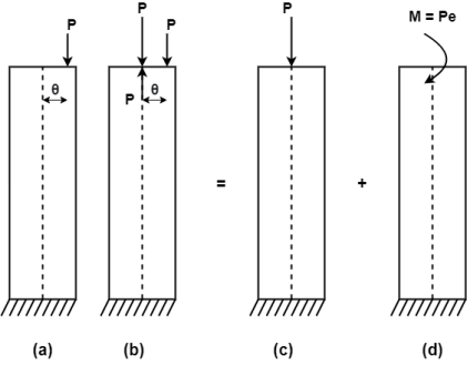
3. Eccentricity:
- It is a horizontal distance between the line of action of force and the centroidal axis.
- It is denoted by e.
- It produces bending stresses in the member.
References:
- Timoshenko, S. And Young, D. H., “Elements of Strength of Materials”, DVNC, New York USA.
- Kazmi, S. M. A., “Solid Mechanics” TMH, Delhi, India.
- Hibbeler, R. C. Mechanics of Materials. 6th ed. East Rutherford, NJ: Pearson Prentice Hall, 2004
- Crandall, S. H., N. C. Dahl, and T. J. Lardner. An Introduction to the Mechanics of Solids 2nd ed. New York, NY: McGraw Hill, 1979
- Laboratory Manual of Testing Materials - William Kendrick Hall