Unit - 4
Gas Power Cycles and Refrigeration cycles
OTTO CYCLE:
Otto cycle is a thermodynamic cycle upon which a spark ignition engine works. Spark Ignition (or SI) engine uses petrol (or Gasoline) as fuel. Otto cycle was invented by Nicolas Otto in 1876.
Spark ignition engine is a type of internal combustion engines.
Below are P-V and T-S Diagrams of the Otto Cycle.
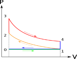
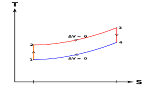
Figure: p-v and t-s diagram of otto cycle
Otto Cycle is comprised of four processes (apart from the intake and exhaust process)
Process 1-2: This process comes after intake process. In case of SI engines, intake is a mixture of gasoline and air, also known as charge. In this process charge is compressed in isentropic manner. Temperature raised from T1 to T2 and volume decrease from V1 to V2.
Process 2-3: In this process the fuel gets blasted with the help of external spark (that is why the engine is known as spark ignition engine). This process is a constant volume heat addition process. Temperature raised from T2 to T3
.
Q2-3= CV(T3-T2)
Process 3-4: After the combustion process, the exhaust gases expend. This process is an isentropic expansion process. No heat is interchanged. The temperature falls from T3 to T4 and volume increase from V3 to V4.
Process 4-1: After the expansion process, exhaust valve opens. This results into sudden drop of pressure inside engine cylinder. This process is a constant volume heat rejection process.
Q4-1= CV(T4-T1)
Process 0-1 is the intake process and process 1-0 is the exhaust process.
Efficiency η = 1 – 1 / (r)y-1
DIESEL CYCLE
Diesel cycle is a gas power cycle invented by Rudolph Diesel in the year 1897. It is widely used in diesel engines.
Diesel cycle is similar to Otto cycle except in the fact that it has one constant pressure process instead of a constant volume process (in Otto cycle).
Diesel cycle can be understood well if you refer its p-V and T-s diagrams.
P-V and T-s Diagrams of Diesel Cycle:
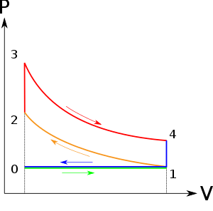
|
|
Figure: Diesel Cycles
Processes in Diesel Cycle:
Diesel cycle has four processes. They are:
Process 1-2: Isentropic Compression
In this process, the piston moves from Bottom Dead Centre (BDC) to Top Dead Centre (TDC) position. Air is compressed is entropically inside the cylinder. Pressure of air increases from p1 to p2, temperature increases from T1 to T2, and volume decreases from V1 to V2. Entropy remains constant (i.e., s1 = s2). Work is done on the system in this process (denoted by Win in the diagrams above).
Process 2-3: Constant Pressure Heat Addition
In this process, heat is added at constant pressure from an external heat source. Volume increases from V2 to V3, temperature increases from T2 to T3 and entropy increases from s2 to s3.
Heat added in process 2-3 is given by
Qin = mCP (T3 − T2) kJ ………… (i)
Where,
m→ Mass of air in kg
Cp → Specific heat at constant pressure in kJ/kg K
T2 → Temperature at point 2 in K
T3 → Temperature at point 3 in K
Process 3-4: Isentropic Expansion
Here the compressed and heated air is expanded isentropic ally inside the cylinder. The piston is forced from TDC to BDC in the cylinder. Pressure of air decreases from p3 to p4, temperature decreases from T3 to T4, and volume increases from V3 to V4. Entropy remains constant (i.e., s3 = s4). Work is done by the system in this process (denoted by Wout in the p-V and T-s diagrams above).
Process 4-1: Constant Volume Heat Rejection
In this process, heat is rejected at constant volume (V4 = V1). Pressure decreases from P4 to P1, temperature decreases from T4 to T1 and entropy decreases from s4 to s1.
Heat rejected in process 4-1 is given by
Qout = mCv (T4 − T1) kJ ………… (ii)
Where,
m→ Mass of air in kg
Cv → Specific heat at constant volume in kJ/kgK
T2 → Temperature at point 2 in K
T3 → Temperature at point 3 in K
Dual Combustion cycle:
The combustion process in a spark ignition engine does not occur exactly at constant volume, nor does the combustion process in an actual compression ignition engine occur exactly at constant pressure, therefore another idealized cycle known as Dual cycle has been developed that more closely approximate the actual spark-ignition and compression-ignition engines. The p-v and T-s diagrams of Dual cycle are shown in Fig. 45.1. In this cycle, part of heat addition occurs at constant volume while the rest is at constant pressure. The dual cycle is also called mixed or limited pressure cycle.
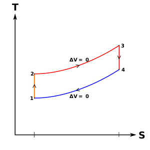
Figure: Dual cycle
In a dual cycle, the system executing the cycle undergoes a series of five processes: two isentropic (reversible adiabatic) processes alternated with two isochoric process and one isobaric process:
Dual cycle – PV Diagram
Isentropic compression (compression stroke) – The gas is compressed adiabatically from state 1 to state 2, as the piston moves from intake valve closing point (1) to top dead centre. The surroundings do work on the gas, increasing its internal energy (temperature) and compressing it. On the other hand, the entropy remains unchanged. The changes in volumes and its ratio (V1 / V2) are known as the compression ratio. The compression ratio is smaller than the expansion ratio.
Isochoric compression (ignition phase) – In this phase (between state 2 and state 3) there is a constant-volume (the piston is at rest) heat transfer to the air from an external source while the piston is at rest at top dead centre. This process is similar to the isochoric process in the Otto cycle. It is intended to represent the ignition of the fuel–air mixture injected into the chamber and the subsequent rapid burning. The pressure rises and the ratio (P3 / P2) is known as the “explosion ratio”.
Isobaric expansion (power stroke) – In this phase (between state 3 and state 4) there is a constant-pressure (idealized model) heat transfer to the air from an external source (combustion of the fuel) while the piston is moving toward the V4. During the constant pressure process, energy enters the system as heat Qadd, and a part of work is done by moving piston.
Isentropic expansion (power stroke) – The gas expands adiabatically from state 4 to state 5, as the piston moves from V3 to bottom dead centre. The gas does work on the surroundings (piston) and loses an amount of internal energy equal to the work that leaves the system. Again, the entropy remains unchanged.
Isochoric decompression (exhaust stroke) – In this phase the cycle completes by a constant-volume process in which heat is rejected from the air while the piston is at bottom dead centre. The working gas pressure drops instantaneously from point 5 to point 1. The exhaust valve opens at point 5. The exhaust stroke is directly after this decompression. As the piston moves from bottom dead centre (point 1) to top dead centre (point 0) with the exhaust valve opened, the gaseous mixture is vented to the atmosphere and the process starts anew.
During the Dual cycle, work is done on the gas by the piston between states 1 and 2 (isentropic compression). Work is done by the gas on the piston between stages 2 and 3 (isobaric heat addition) and between stages 2 and 3 (isentropic expansion). The difference between the work done by the gas and the work done on the gas is the network produced by the cycle and it corresponds to the area enclosed by the cycle curve. The work produced by the cycle times the rate of the cycle (cycles per second) is equal to the power produced by the Diesel engine.
Brayton Cycle
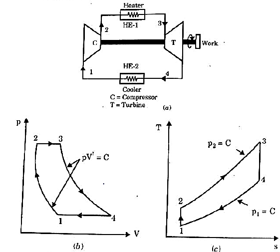
It is theoretical cycle for gas turbines. It is also known as constant pressure cycle for a perfect gas. The basic component of Brayton Cycle is as shown in given figure-
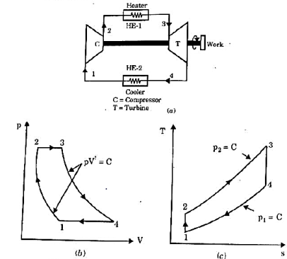
Figure: Brayton Cycle
The components are compressor, heat exchanger, turbine and cooler.
There occur two isentropic processes and two constant pressure processes. Compression and expansion of working fluid is done by isentropic process while addition and rejection of heat is done at constant pressure. In above figure, we can see the p-v and T-s diagram for the cycle.
Process 1-2: Air is being compressed is entropically by compressor between the pressure range p1 to p2.
Process 2-3: It is constant pressure heat pressure heat addition process. In this process temperature increases from T2 to T3 at constant pressure.
Process 3-4: The air is expanded is entropically pressure p2 to p1 and the temperature drops from T3 to T4.
Process 4-1: It is constant pressure heat rejection process as temperature reduces from T4 to T1.
Now, Work done per cycle=Heat added/cycle-Heat rejected/cycle
Heat addition in process 2-3=mCp(T3-T2)
Heat rejected in process 4-1= mCp(T4-T1)
Work done per cycle=mCp(T3-T2)-MCp(T4-T1)


From process 1-2


Similarly, from process 3-4

Putting the values  and
and  in equation


The above equation shows that the efficiency of the ideal Brayton cycle increases with the pressure ratio.

Figure: Effect of pressure ratio on the efficiency of Brayton Cycle
Actual Brayton cycles differ from the ideal cycles in all the four processes.
• The compression process and expansion processes are non-isentropic.
• Pressure drops during heat addition and heat rejection.
• The presence of irreversibilities causes the above deviations.
The deviation of actual compressors and turbines from the isentropic versions can be accounted for by using the isentropic efficiencies.
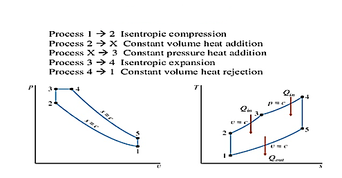
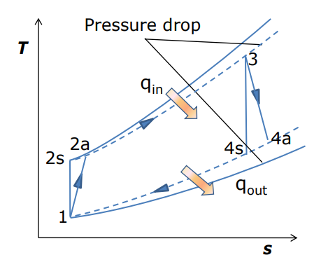
Figure: Actual Brayton cycle T-s diagram


Where, 2a and 4a are the actual states at the compressor and turbine exit and 2s and 4s are the corresponding isentropic states.
As a result of non-isentropic compression and expansion, the compressor needs more work than the ideal cycle and turbine generates less work.
Isentropic efficiencies reflect the amount of deviation of the actual compression/expansion processes from the ideal.
Total pressure losses in the heat addition/rejection processes also need to be considered.
Other differences between ideal and actual Brayton cycles
These parameters are often used in actual cycle analysis.
The net work of a gas-turbine cycle is the difference between the turbine work output and the compressor work input. It can be increased by either decreasing the compressor work or increasing the turbine work, or both. The work required to compress a gas between two specified pressures can be decreased by carrying out the compression process in stages and cooling the gas in between: multi-stage compression with intercooling. Similarly, the work output of a turbine can be increased by: multi-stage expansion with reheating. As the number of stages of compression and expansion are increased, the process approaches an isothermal process. A combination of intercooling and reheating can increase the network output of a Brayton cycle significantly.
Gas-turbine engines are widely used to power aircrafts because of their light-weight, compactness, and high power-to-weight ratio. Aircraft gas turbines operate on an open cycle called jet-propulsion cycle. Some of the major differences between the gas-turbine and jet-propulsion cycles are:
Gases are expanded in the turbine to a pressure where the turbine work is just equal to the compressor work plus some auxiliary power for pumps and generators i.e., the network output is zero
Since the gases leave at a high velocity, the change in momentum that the gasundergoes provides a thrust to the aircraft
The fluid passes through a diffuser first where it is decelerated (gas pressure increases)
Typically operate at higher pressure ratios, often in the range of 10 to 25
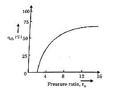
Figure: T-s diagram for ideal turbojet cycle
Diffuser (1-2) decelerates the incoming flow relative to the engine a pressure rise known as a ram effect occurs, V (↓), P (↑). It can be explained through the
Bernoulli’s equation: 
Compressor, Burner and Turbine (2-5)
2-3: isentropic compression
3-4: constant pressure heat addition
4-5: isentropic expansion through the turbine during which work is developed
Turbine power just enough to drive the compressor
Air and fuel are mixed and burned in the combustion chamber at constant pressure
Air velocity leaving the turbine is small and can be neglected
Nozzle (5-6)
Isentropic expansion through the nozzle, air accelerates and the pressure deceases gases leave the turbine significantly higher in pressure than atmospheric pressure
Gases are expanded to produce a high velocity, Ve >> Vi results in a thrust
The pressure at the inlet and the exist of a turbojet engine are identical (the ambient pressure); thus, the net thrust developed by the engine is:

For an aircraft cruising in still air, Vinlet is the aircraft velocity. The power developed from the thrust of the engine is called the propulsive power:

The thermal efficiency is defined based on the propulsive power. This then becomes a measure of how efficiently the energy released during the combustion process is converted to propulsive energy.

Afterburner
Afterburner is popular in military aircrafts and it is used whenever a need for extra thrust arises, such as for short take offs or combat conditions. Afterburner is similar to a reheat device; it is located after the turbine and before the nozzle. It produces a higher temperature (and pressure) at the nozzle inlet, results in an increase in velocity (and thrust).
In refrigerating systems, the Carnot cycle considered is the reversed Carnot cycle. We know that a heat engine working on Carrot cycle has the highest possible efficiency. Similarly, a refrigerating system working on the reversed Carnot cycle, will have the maximum possible coefficient of performance. We also know that it is not possible to make an engine working on the Carnot cycle. Similarly, it is also not possible to make a refrigerating machine working on ii: reversed Carnot cycle. However, it is used as the ultimate standard of comparison. A reversed Carrot cycle, using air as working medium (or refrigerant) is shown on p-v and T-s diagram in Fig. 35.2 (a) and (b) respectively. At point I, let p1, v and T1 be the pressure, volume and temperature of air respectively.
The four stages of the cycle are as follows: I. First stage expansion:). The air is expanded is entropically as shown by the curve 1-2 on p-v and T-s diagrams. The pressure of air decreases from p1 to p2, specific volume increases from v to v2 and the temperature decreases from i to T2. We know that during isentropic expansion, no heat is absorbed or rejected by the air. 2. Second stage (isothermal expansion). The air is now expanded isothermally (i.e., at constant temperature. T2 = T3) as shown by the curve 2-3 on p-v and T-s diagrams. The pressure of air decreases from p2 to p3 and the specific volume increases from v2 to v3 We know that the heat absorbed by the air (or heat extracted from the cold body) during isothermal expansion per kg of air.

3. Third stage (Isentropic compression). The air is compressed is entropically as shown by the curve 3-4 on p-v and T-s diagrams. During this process, the pressure of air increases from J to p4. specific volume decreases from V3 to 04 and temperature increases from 1' 3 to T4. We know that during isentropic compression, no heat is absorbed Cr rejected by the air.
4. Fourth stage (Isothermal compression). The air is now compressed isothermally (i.e., at constant temperature, T4 = T1) as shown by the curve4- I on p-v and T-s diagrams. During this process, the pressure of air increases fromp4 top1 and specific volume decreases from v 4 to v 1. We know that the heat rejected by the air during isothermal compression per kg of air,

We know that work done during the cycle per kg of air,
 Heat rejected –Heat absorbed

 Coeffiecient of performance of the refrigeration system working on reversed Carnot cycle,


Though the reversed Carnot cycle is the most efficient between the fixed temperature limits. yet no refrigerator has been made using this cycle. This is due to the reason that the isentropic processes of the cycle require high speed while the isothermal processes require an extremely low speed. This variation in speed of air is not practicable. Note: We have already discussed that COP. of a heat pump.


C.O.P or efficiency of a heat engine


Temperature Limitations for Reversed Carnot Cycle
We have seen in the previous article that the C.O.P of a reversed Carnot cycle is given by
C.O.P
Where  Higher temperature, and
 Lower temperature
The C.O.P. of the reversed Carnol cycle may be improved by I. decreasing the higher temperature (i.e., temperature of hot body. T1). or 2. increasing the lower temperature (i.e., temperature of cold body. T2).
Process 1-2: Reversible, adiabatic compression in a compressor
Process 2-3: Reversible, isobaric heat rejection in a heat exchanger
Process 3-4: Reversible, adiabatic expansion in a turbine
Process 4-1: Reversible, isobaric heat absorption in a heat exchanger

Process 1-2: Gas at low pressure is compressed is entropically from state 1 to state 2. Applying steady flow energy equation and neglecting changes in kinetic and potential energy, we can write:


And 
Where 
Process 2-3: Hot and high-pressure gas flows through a heat exchanger and rejects heat sensibly and isobarically to a heat sink. The enthalpy and temperature of the gas drop during the process due to heat exchange, no work transfer takes place and the entropy of the gas decreases. Again, applying steady flow energy equation and second T ds equation:


Process 3-4: High pressure gas from the heat exchanger flows through a turbine, undergoes isentropic expansion and delivers network output. The temperature of the gas drops during the process from T 3 to T 4. From steady flow energy equation:


and 
where  pressure ratio
Process 4-1: Cold and low-pressure gas from turbine flows through the low temperature heat exchanger and extracts heat sensibly and isobarically from a heat source, providing a useful refrigeration effect. The enthalpy and temperature of the gas rise during the process due to heat exchange, no work transfer takes place and the entropy of the gas increases. Again, applying steady flow energy equation and second T ds equation:


From the above equations, it can be easily shown that

applying 1st law of thermodynamics to the entire cycle:

The COP of the reverse Brayton cycle is given by:

Using the relation between temperature and pressures, the COP can also be written as:

For fixed heat rejection temperature (T 3) and fixed refrigeration temperature (T1), the COP of reverse Brayton cycle is always lower than the COP of reverse Carnot cycle (Figure), that is

Vapour-compression refrigeration or vapor-compression refrigeration
system (VCRS), in which the refrigerant undergoes phase changes, is one of the many refrigeration cycles and is the most widely used method for air-conditioning of buildings and automobiles.
Vapor-compression cycle refrigeration is a process that uses the physics of phase change heat transfer and the unique properties of a refrigerant to transfer heat from a relatively cold source to a hot medium. Simply stated, refrigeration systems efficiently move heat from a cold source to a hot heat sink (normally air). The components in the basic refrigeration system are:
The compressor, condenser, expansion valve, and evaporator.
The heart of the system is the compressor. The compressor takes in a low temperature, low pressure refrigerant vapor, and compresses it into a high temperature, high pressure vapor. This high temperature/pressure vapor then enters the condenser where heat is removed to either air or water. As the heat is removed, the energy stored in the high-pressure gas is released and the refrigerant gives up its latent heat as it reverts to a hot liquid.
This hot, high temperature liquid then exits the condenser and enters the expansion valve, where it undergoes a pressure drop causing some of the hot gas to vaporize. This lowers the temperature of the refrigerant stream. The refrigerant at the exit of the expansion valve is a low temperature two-phase fluid.
This two-phase fluid enters the evaporator where it is exposed to the heat source. The heat from the source boils off the refrigerant through phase change heat transfer, and the low temperature, low pressure gas enters the compressor, completing the cycle.
It is useful to understand the refrigerant cycle in the quadrant shown in Figure 13. The high pressure, high temperature upper half allows the refrigerant to become significantly hotter than ambient air, forcing heat transfer into a habitually hot environment.
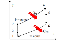
Figure: Vapor Compression System
The low temperature, low pressure half of the cycle allows the refrigerant to absorb heat from a source that is not as hot as the environment. The compressor does the work to raise the pressure, and the expansion valve assures that adequate pressure is retained in the condenser for heat transfer.
The vapor compression cycle can be used to cool air, liquid, or cold plates. All that is required to accomplish this is to modify the evaporator to accommodate the systems that are being cooled. To create an air-cooling system, the evaporator acts as a refrigerant to an air heat exchanger. The air-cooling system is used in buildings, automobiles, and in electronics enclosures where air cooled rack-mounted equipment is being cooled.
To cool liquid, the evaporator again acts as a refrigerant, this time to a liquid heat exchanger, with the pumped liquid being cooled by the evaporating refrigerant. The liquid cooled system is used for systems such as lasers, electronics, and medical devices that are designed for liquid cooling.
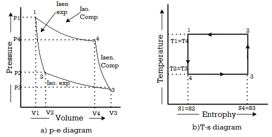
Figure: Vapor Compression Cycle
The thermodynamics of the vapor compression cycle can be analyzed on a temperature versus entropy diagram as depicted in Figure 2. At point 1 in the diagram, the circulating refrigerant enters the compressor as a saturated vapor. From point 1 to point 2, the vapor is entropically compressed (compressed at constant entropy) and exits the compressor as a superheated vapor. Superheat is the amount of heat added above the boiling point.
From point 2 to point 3, the vapor travels through part of the condenser which removes the superheat by cooling the vapor. Between point 3 and point 4, the vapor travels through the remainder of the condenser and is condensed into a saturated liquid. The condensation process occurs at essentially constant pressure.
Between points 4 and 5, the saturated liquid refrigerant passes through the expansion valve and undergoes an abrupt decrease of pressure. That process results in the adiabatic flash evaporation and auto-refrigeration of a portion of the liquid (typically, less than half of the liquid flashes). The adiabatic flash evaporation process is isenthalpic (occurs at constant enthalpy).
Between points 5 and 1, the cold and partially vaporized refrigerant travels through the coil or tubes in the evaporator where it is totally vaporized by the warm air (from the space being refrigerated) that a fan circulates across the coil or tubes in the evaporator. The evaporator operates at essentially constant pressure and boils off all available liquid there after adding 4–8 kelvins of superheat to the refrigerant in order to make sure the liquid has evaporated completely. This is a safeguard for the compressor, as it cannot pump liquid. The resulting refrigerant vapor returns to the compressor inlet at point 1 to complete the thermodynamic cycle.
The above discussion is based on the ideal vapor-compression refrigeration cycle which does not take into account real world items like frictional pressure drop in the system, slight internal irreversibility during the compression of the refrigerant vapor, or non-ideal gas behaviour.
The simple vapour absorption system, as shown in fig consists of an absorber, a pump, a generator and a pressure reducing value to replace the compressor of vapour compression system. The other components of the system are condenser, receiver, expansion value and evaporator as in the vapour compression system
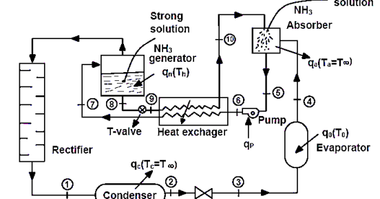
In this system, the low-pressure ammonia vapour leaving the evaporator enters the absorber where it is absorbed by the cold water in the absorber. The water has the ability to absorb very large quantities of ammonia vapour and the solution, thus formed, is known as aqua-ammonia. The absorption of ammonia vapour in water lowers the pressure in the absorber which in turn draws more ammonia vapour from the evaporator and thus raises the temperature of solution. Some form of cooling arrangement (usually water cooling) is employed in the absorber to remove the heat of solution evolved there. This is necessary in order to increase the absorption capacity of water, because at higher temperature water absorbs less ammonia vapour. The strong solution thus formed in the absorber is pumped to the generator by the liquid pump. The pump increases the pressure of the solution up to 10 bar.
The strong solution of ammonia in the generator is heated by some external source such as gas or steam. During the heating process, the ammonia vapour is driven off the solution at high pressure leaving behind the hot weak ammonia solution in the generator. This weak ammonia solution flows back to the absorber at low pressure after passing through the pressure reducing value. The high-pressure ammonia vapour from the generator is condensed in the condenser to a high-pressure liquid ammonia. This liquid ammonia is passed to the expansion value through the receiver and then to the evaporator. This completes the simple vapour absorption cycle.
References:
1. Engineering Thermodynamics by P. K. Nag, Publisher: TMH
2. Engineering Thermodynamics by P. Chattopadhyay, OXFORD
3. Fundamentals of Thermodynamics by Sonntag, Borgnakke, Van Wylen, John Wiley & Sons
4. Thermodynamics An Engineering Approach by Yunus A. Cingel and Michale A. Boles, TMH
5. Engineering Thermodynamics by M. Achyuthan, PHI