Unit – 4
T.T.T. diagram
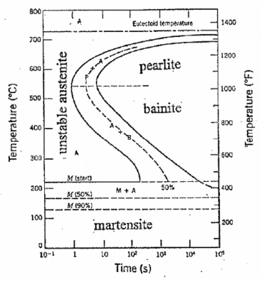
Suppose we rapidly cool steel of eutectoid composition (0.8 % C) from the austenitic range down to some temperature where α and Fe3C are the stable phases. If we could observe the resulting transformation process, we would find that, initially, the material is 100% unstable austenite. After some time, the ferrite and cementite would begin to form (either as pearlite or bainite) and after sufficient time, the transformation of the austenite would be complete. This process is represented by the so-called Time-Temperature- Transformation (TTT) diagram shown in Figure 22. Notice that, if we suddenly cool the austenite to a temperature Ms (martensite start) or less, some martensite will form. The remaining austenite will then transform to bainite. If we suddenly cool the material to temperature Mf (martensite finish), we will have 100% martensite and no further transformation will occur
Continuous-Cooling Transformation Diagram for Iron-Carbon Systems
The TTT diagram refers strictly to the cases where the steel is suddenly cooled from the austenite (γ) range down to some new temperature. In most instances, the cooling is not instantaneous, but rather occurs at a finite rate. As an approximation, the TTT diagram may also be used in this case, but a more accurate Continuous-Cooling Transformation (CCT) Diagram should be used when available. This diagram is shown in Figure 23 for a eutectoid steel.
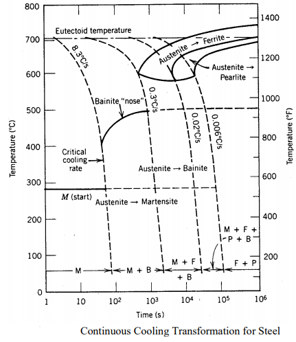
If we suddenly cool the material at such a rapid rate, that when plotted on the TTT diagram the time vs temperature line does not intersect the γ + α + carbide phase (also known as "missing the knee" but instead goes straight from the γ stable through the γ unstable region to a temperature Mf (martensite finish), we will have martensite with no additional phase. When the cooling rate is such that both the beginning and end curves are reached before reaching the martensitic zone, no (or very little) martensite will form.
By varying the amount of martensite present in the material, the mechanical properties of the steel can be varied. Martensite alone is very hard and strong but also is extremely brittle. A compromise between strength and ductility can be reached by varying the amount of martensite present in equilibrium with ferrite and carbide.
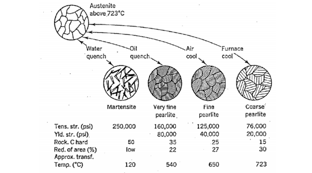
| Martensite | Very fine pearlite | Fine pearlite | Coarse pearlite |
Tens. Str. (psi) | 250,000 | 160,000 | 125,000 | 76,000 |
Yld. str.(psi) |
| 80,000 | 40,000 | 20,000 |
Rock. C hard | 50 | 35 | 25 | 15 |
Red. of area(%) | Low | 22 | 27 | 30 |
Approx. transf. Temp. (*C) | 120 | 50 | 650 | 723 |
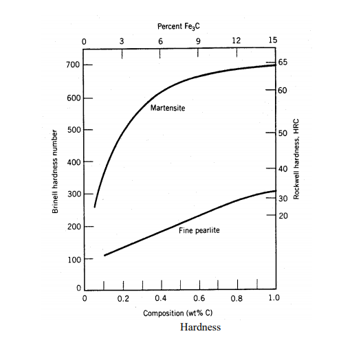
The procedure for forming this mixed material is called "heat treatment." First, the material is rapidly cooled (quenched) so as to form nearly 100% martensite. At room temperature, this nonequilibrium phase is, for all practical purposes, stable and will not further transform to ferrite and carbide. If we then take the 100% martensite and heat it to an elevated temperature (say 700o C) and hold it there for some length of time (tempering), the martensite can be softened (stress relieved) and decompose. The changes that occur are temperature dependent and range from merely a reduction in strain-energy and dislocation density to microstructural changes within the martensite itself. The end result is a material that retains some of the high strength and hardness characteristics of pure martensite while restoring some ductility. As shown in Figure 25, the hardness obtainable with martensite is dependent on the carbon content. Since it is the "trapping" of the carbon atoms which forms martensite, and thus hardens the metal, pure iron cannot be hardened by quenching
When a material is plastically strained the yield, stress is increased. In many of the manufacturing techniques listed earlier, the material is plastically deformed in order to fabricate the desired shape. As Figure 16 shows, although this may significantly increase the yield strength of the material, it also makes it more brittle. This change is a result of the dislocation density, or imperfections in the lattice, increasing as a result of the deformation.
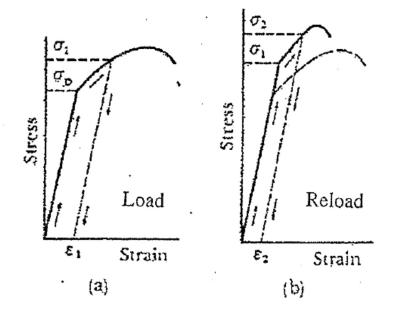
If we take a work-hardened material and subject it to a sufficiently high temperature for a specified time, we can reduce the dislocation density and the yield stress will return to its initial value. This is known as annealing the material, which is a form of heat treatment. Due to other aspects, such as recrystallization, subjecting the work-hardened material to a high temperature for too long a
Steels that have undergo plastic deformation consist of pearlites which are irregularly shaped and relatively large, but varying in size. Normalizing is a heat treatment used on steel so as to refine its crystal structure and produces a more uniform and desired grain size distribution. Fine grained pearlites are tougher than coarse grained ones. Normalization eliminates internal stresses, strains and improves the mechanical properties of the steel, such as improving its toughness and machinability. A better ductility can also be obtained without compromising the hardness and strength.
Normalizing is accomplished by heating the steel to a temperature above the transformation range and into the range of complete austenite. This is dependent on the composition of the steel as indicated by the iron-carbon diagram shown below. The usual normalizing temperature ranges from 815°C to 980°C (1500°F to 1800°F), depending on the steel involved.
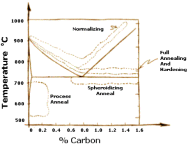
After sufficient time is given for complete transformation to austenite, i.e., austenitizing of the steel, the alloy is air-cooled to a temperature substantially below the transformation range. The air-cooling avoids excessive proeutectoid segregation. The cooling rate is usually in the range of 500 to 1000 °C/h (900 to 1800 °F/h).
The final microstructure consists of fine pearlite and an absence of massive proeutectoid ferrite. Normalizing is commonly specified for plates of pressure vessel quality hence to ASTM standards above 1 ½ inch in thickness.
Tempering is a heat treatment process that alters the mechanical properties (typically ductility and hardness) and relieves internal stresses of a steel. Tempering allows carbon trapped in a martensitic microstructure to disperse, and enables the internal stresses to be released from the steel that may have been created from prior operations.
The Tempering Process
Tempering is performed by elevating the steel to a set point below its lower critical temperature, typically following a hardening operation. Once this temperature is reached, it is held there for a specified amount of time. The exact temperature and time depend on several factors such as the type of steel and desired mechanical properties.
To get the steel to its critical temperature, some type of heating device must be used. Common devices include gas furnaces, electrical resistance furnaces, or induction furnaces. Often, this heating is done in a vacuum or with an inert gas to protect the steel from oxidation. Once the furnace achieves the desired temperature, a dwell time occurs. Following the dwell time, the furnace is shut off and the steel is allowed to cool at predetermined rate.
Why Is Steel Tempered?
Tempering steel after a hardening process allows for a middle ground of hardness and strength. This is achieved by allowing the carbon diffusion to occur within a steel microstructure. When steel is hardened, it can become excessively brittle and hard. However, when not hardened, the steel may not have the strength or abrasion resistance needed for its intended application. Tempering also improves the machinability and formability of a hardened steel, and can reduce the risk of the steel cracking or failing due to internal stresses.
When Is Tempering Used?
Grain structure
the studied alloy exhibits fully recrystallized structure after extrusion. The distribution of grain size is uniform and the average grain size is 12.25 ± 0.15 μm. In addition, some low angle grain boundaries indicated by laurel-green line could also be observed, which indicated that the dynamic recrystallization (DRX) mechanism for the studied alloy is continuous DRX dominated. Furthermore, the presence of nano-scaled precipitates and solutioned Sn in the matrix are beneficial to refine the size of DRX grains through Zener-drag effect
Dynamic Precipitates
illustrates the XRD results of the extruded dilute TMX-1.0 alloy. The results indicate that the studied alloy mainly comprises α-Mg, Mg2Sn, and Mg2Ca phases. It was reported that Mg2Ca rather than CaMgSn phase was formed in Mg-Sn-Ca-based alloys when the Sn/Ca mass ratios were lower than ~2.5:1. The intensities of the peaks corresponding to the Mg2Sn and Mg2Ca phases in the extruded dilute alloy are relatively weak because of the low concentrations of alloying elements.
Tensile Properties
The engineering tensile stress-strain curve and the corresponding work-hardening response of the extruded dilute TMX-1.0 alloy are shown in the tensile yield strength, ultimate tensile strength and elongation of the extruded dilute alloy are 213 and 266 MPa, and 21%, respectively. gives the comparison of tensile properties among the extruded dilute TMX-1.0 alloy in the present study with other Mg-based extruded alloys. It should be noted that TYS of the studied alloy is higher than that of Mg-Al and/or Mg-Zn based alloys studied in, and Some reported Mg-Al-Zn alloys exhibit higher TYS (while these alloys present relatively poor elongation when compared with the studied TMX-1.0 alloy. Overall, the combined tensile properties of the studied alloy are at an acceptable level.
The following points highlight the four main factors affecting the hardenability of steel. The factors are:
1. Grain Size
2. Austenitising Temperature and Time
3. Carbon Content of the Steel
4. Alloying Elements in Steel.
Grain Size:
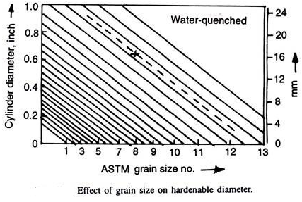
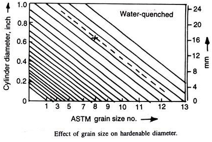
Grain boundaries are the preferential nucleation sites for ferrite and pearlite. If austenitic grain size is large, the grain boundary area decreases. This means that nucleation sites are being reduced in number. Thus, these transformations are slowed down. Thus, hardenability of a steel increases as its grain size increases. Grange gave the Fig. 4.21 correlating grain size and hardenable diameter (for 90% martensite, water quenched). If hardenable diameter and the grain size is indicated by a cross, then the hardenable diameter at any other grain size can be obtained by drawing parallel to diagonal lines as illustrated by dashed line.
This method of increasing hardenability by increasing the grain size of the steel is normally avoided as the coarse grains have deleterious effect like increased brittleness, more tendency to quench-cracks, etc.
The beneficial effects of the alloying elements in steel in increasing hardenability is realised only when the alloying elements are made to go into solution and form homogeneous austenite by heating the steel to proper austenitising temperature and enough time at this temperature. A too high a temperature and/or too long austenitising time may coarsen the austenite grains (which too results in increased hardenability) with its resultant bad effects.
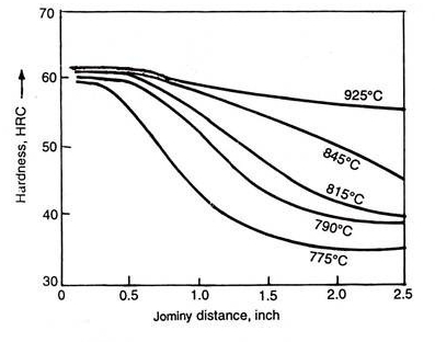
Proper choice should be made after examining the size of the part, microstructure of incoming steel, amount and type of alloying elements in steel, etc. Normally, the effect, if proper austenitising temperature and time are used, is not substantial, however Fig. 4.22 indicates large effect on Jominy curve by using different austenitising temperatures.
Most metallic alloying elements (except cobalt) slow down the ferrite and pearlite reactions, i.e., increase the stability of austenite resulting in shifting the CCT curves towards right. This means, the hardenability is increased (provided alloying elements are dissolved in austenite). Undissolved inclusions such as carbides, nitrides, non-metallic inclusions, and even heterogeneity of austenite decrease the hardenability.
For example, presence of undissolved alloy carbides not only depletes the austenite of the alloying elements but also the carbon present as carbide. Their presence in dissolved state in austenite would have increased hardenability. These as carbides decrease the grain growth, which otherwise (dissolved in austenite) would have increased the hardenability.
Most of these inclusions also help in pearlite formation, a factor which decreases the hardenability. Cobalt increases the nucleation and growth of pearlite, thus shifts the CCT curve towards left to decrease the hardenability. However, quantitative assessment of effects of different elements is needed.
Although, alloying elements shift the CCT diagrams towards right, the effect of an element on pearlitic and bainitic region is not normally same. A cooling rate which may be sufficient to suppress the pearlitic reaction may not be large enough to prevent bainite formation. In such a case, the critical cooling rate for ≈ 100% martensite formation is governed by the bainite reaction, and the non-martensitic product shall be bainite.
Carbon Content of the Steel:Carbon fixes the maximum attainable hardness on quenching. It also increases the hardenability of the steel as it stabilises austenite resulting in shifting the CCT curve to the right as its content increases up to 0.77%, but beyond that hardenability decreases.
This is because the austenitising temperatures used for hypereutectoid steels have undissolved carbides in them, which invariably act as nuclei for the pearlitic transformation to shift the CCT curves towards left (with increasing carbon), and thus, decrease hardenability. Pure Fe-C steels have very poor hardenability.
For example, DI for 0.77% carbon and ASTM grain size 8 is only 0.28 inch i.e., in an ideal quench such carbon steel can harden up 1/4″ diameter. Fortunately, commercial steels always have manganese and other elements by the process of making steel economically, which increase their hardenability.
Optical property deals with the response of a material against exposure to electromagnetic radiations, especially to visible light. When light falls on a material, several processes such as reflection, refraction, absorption, scattering etc.
1. Refraction:When light photons are transmitted through a material, they cause polarization of the electrons in the material and by interacting with the polarized materials, photons lose some of their energy. As a result of this, the speed of light is reduced and the beam of light changes direction.
2. Reflection:When a beam of photons strikes a material, some of the light is scattered at the interface between that we media even if both are transparent. Reflectivity, R, is a measure of fraction of incident light which is reflected at the interface.
Reflectivity is defined as fraction of light reflected at an interface.

• Where I0 and IR are the incident and reflected bean intensities respectively.
• If the material is in a vacuum or in air then

• If the material is in some other medium with an index of refraction of ni, then 

• The above equations apply to the reflection from a single surface and assume normal incidence. The value of R depends upon the angle of incidence.
• Materials with a high index of refraction have a higher reflectivity than materials with a low index. Because the index of refraction varies with the wavelength of the photons, so does the reflectivity.
• In metals, the reflectivity is typically on the order of 0.90-0.95, whereas for glasses it is close to 0.05. The high reflectivity of metals is one reason that they are opaque. High reflectivity is desired in many applications including mirrors, coatings on glasses, etc.
3. Absorption:When a light beam is striked on a material surface, portion of the incident beam that is not reflected by the material is either absorbed or transmitted through the material. The fraction of beam that is absorbed is related to the thickness of the materials and the manner in which the photons interact with the material’s structure.
4. Rayleigh scattering:Here photon interacts with the electron orbiting around an atom and is deflected without any change in photon energy. This is more vital for high atomic number atoms and low photon energies. Ex. Blue colour in the sunlight gets scattered more than other colors in the visible spectrum and thus making sky look blue.
b. Compton Scattering:
In this incident photon knocks out an electron from the atom losing some of its energy during the process.
5. Transmission:The fraction of beam that is not reflected or absorbed is transmitted through the material. Thus, the fraction of light that is transmitted through a transparent material depends on the losses incurred by absorption and reflection. Thus, R + A + T = 1
where R = reflectivity,
A = absorptivity, and
T = transitivity
6. Thermal Emission:When a material is heated electrons are excited to higher energy levels generally in the outer energy levels where the electrons are less strongly bound to the nucleus. These excited electrons, upon returning back to the ground state, release photons in process termed as thermal emission.
By measuring the intensity of a narrow band of the emitted wavelengths with a pyrometer, material’s temperature can be estimated.
7. Electro-Optic Effect:The behaviour of a material in which its optical isotropic nature changes to anisotropic nature on application of an electric field. This effect is seen in LiNbO3, LiTiO3 etc.
8. Photoelectric Effect:Phenomenon in which the ejection of electrons from a metal surface takes place, when the metal surface is illuminated by light or any other radiation of suitable frequency (or wavelength). Several devices such as phototube, solar cell, fire alarm etc. work on this effect (principle).
9. Photo Emissivity:Phenomenon of emission of electrons from a metal cathode, when exposed to light or any other radiations.
10. Brightness:Power emitted by a source per unit area per unit solid angle.
Photo Conductivity- Phenomenon of increase in conductivity of a semi-conductor due to excess carriers arisen from optical luminescence.
Optical Properties of Non-Metals:
i. These materials may be transparent, translucent, or opaque. Therefore, they exhibit different optical properties such as reflection, refraction, absorption and transmission. The phenomenon of refraction is more dominant in them.
ii. The non-metals which are transparent are generally coloured due to light absorption and remission in the visible region by them. Absorption of light occurs due to: Electronic polarization.
iii. Excitation of electrons from filled valence band to empty state within conduction band, and Wide band gaps in dielectric materials.
iv. The non-metallic transparent materials transmit light due to net energy formed by absorption and reflection processes.
Optical Properties of Metals:
i. In metals, the valence band is partially filled and so there are large number of quasi continuous vacant energy levels available within the valence band. When light is incident on metals the valence electrons absorb all frequencies of visible light and get excited to vacant states inside the valence band (intra-band transitions). This result in the opacity of metals.
ii. The total absorption of light by the metal surface is within a very thin outer layer of less than 0.1 jam. The excited electrons return back to lower energy states thereby causing emission of radiation from the surface of the metal in the form of visible light of the same wavelength. This emitted light which appears as the reflected light is the cause of the lustrous appearance of metals.
iii. In copper, inter-band transitions occur for energies greater than 2.2 eV i.e., the photons of energy greater than 2.2 eV are strongly absorbed. This energy corresponds to wavelength below 5625 Å. This means that the radiation in the blue-violet range is absorbed. This is reason for the reddish-orange colour of copper.
iv. In silver and aluminium, there is no absorption in the full range of visible radiation. So, the re-emission occurs over the entire wavelength range of the visible spectrum due to which the white colour of these metals exists.
Atomic theory
Is the study of matter-matter and light-matter interactions; at the scale of one or a few atoms and energy scales around several electron volts. The three areas are closely interrelated.
AMO theory includes classical, semi-classical and quantum treatments. Typically, the theory and applications of emission, absorption, scattering of electromagnetic radiation (light) from excited atoms and molecules, analysis of spectroscopy, generation of lasers and masers, and the optical properties of matter in general, fall into these categories
• Laser is an acronym for light amplification by stimulated emission of radiation. It is in fact special application of luminescence.
• Unlike most radiation processes, such as luminescence, which produce incoherent light, the light produced by laser emission is coherent.
• This is based on the fact that in certain materials, electrons excited by a stimulus produce photons which in turn excite additional photons of identical wavelength. Thus, a large amplification of the photons emitted in the material occurs.
• Lasers are useful in many applications such as welding, metal cutting, heat treatment, surgery, mapping, reading compact disks, etc. Ex.: Ruby, single crystal of Al2O3 doped with little amount of Cr2O3; yttrium aluminium garnet (Y3Al5O12 – YAG) doped with neodymium, Nd; CO2 gas; He-Ne gas; some semi-conductors like GaAs and InGaAsP
Optical fibre is the technology associated with data transmission using light pulses traveling along a long fibre which is usually made of plastic or glass
Optical Fibre Working Principle
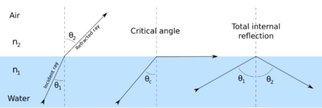
Optical fibre works on the principle of total internal reflection. When light traveling in an optically dense medium hits a boundary at a steep angle (larger than the critical angle for the boundary), the light is completely reflected. This is called total internal reflection.
This effect is used in optical fibres to confine light in the core. Light travels through the fibre core, bouncing back and forth off the boundary between the core and cladding. Because the light must strike the boundary with an angle greater than the critical angle, only light that enters the fibre within a certain range of angles can travel down the fibre without leaking out.
This range of angles is called the acceptance cone of the fibre. The size of this acceptance cone is a function of the refractive index difference between the fibre’s core and cladding.
Types Of Optical Fibre
Optical fibres are classified on different parameters such as refractive index, materials used and mode of propagation of light. Let’s see each classification in detail.
Based on Refractive Index
1. Mono Mode Optical Fibre: It has a very narrow core of diameter about 5𝜇m or less, cladding is relatively big.
2. Multi-mode Optical Fibre: It is again of two types:
(i) Step Index Multi Mode Fibre: The diameter of the core is about 50𝜇m. The core has a constant R. The refractive index then changes to a lower value of 𝜇 which remains constant through the cladding.
(ii) Graded Index Multi Mode Fibre: Refractive index decreases smoothly from its centre to the outer surface of the fibre (cladding). There is no noticeable boundary between core and cladding.
Based on Materials Used
The classification based on the materials used is as follows:
Based on Mode of Propagation of Light
The classification based on the mode of propagation of light is as follows:
Application
Computer networking is one of the major uses of fibre optics in which data is transmitted at a higher bandwidth. Apart from that, fibre optics can also be used for long-distance connections of a computer network to different locations. There are multiple usages of fibre cables.
References:
1. Materials Science and Engineering by V.Raghavan, Prentice Hall of India Pvt.Ltd.
2. Elements of Materials Science & Engineering by Van Vlack, Pearson
3. Mechanical Metallurgy by Dieter, Tata MacGraw Hill
4. Composite Material science and Engineering by K. K. Chawla, Springer
5. Material Science and Metallurgy, by U. C. Jindal, Pearson