Unit - 1
Kinematic fundamental
A mechanism is defined as the assembly of bodies in such a way that motion in one body causes constrained and predictable motion in other bodies. Or we can say a mechanism is a combination of several bodies to produce a specified motion Mechanisms can be classified in following four types:
Classification of Mechanisms
The mechanisms are of the following types:
On the basis of number of links
a. Simple mechanism: A mechanism which has four links.
b. Compound mechanism: A mechanism which has more than four links.
2. On the basis of number of pairs
a. Mechanism having three pairs.
b. Mechanism having 4 pairs.
c. Mechanism having more than 4 pairs.
3. On the basis of motion of particles
a. Planar mechanism: When all the links of the mechanism lie in the same plane.
b. Spatial mechanism: When the links of the mechanism lie in different planes.
Kinematics
Kinematics is the branch of mechanics in which the motion of a particle is studied without consideration of forces. Kinematics of machines deals with the study of the relative motion of machine parts. It involves the study of position, displacement, velocity and acceleration of machine parts.
Kinematic link (or) element
Kinematic link or element is the basic or smallest unit of a mechanism. Generally kinematic links are assumed to be rigid during analysis of kinematic performance of a machine. These links can be classified in following two categories:
Based on number of elements of link | Based on type of structural behaviour |
Binary link: Link which is connected to other links at two points.
| Rigid link. A rigid link is the one which does not deform during the transmission of the motion. e.g., connecting rod, crank etc. |
Ternary link: Link which is connected to other links at three points.
| Flexible link. A flexible link can deform partly during transmission of motion without affecting the transmission. e.g.-belts, ropes, chains and wires. |
Quaternary link: Link which is connected to other links at four points.
| Fluid link. A link in which transmission of motion takes place through the fluid pressure. e.g.- hydraulic presses, jacks and brakes. |
Kinematic pair
Connection between two links is known as a kinematic pair when the relative motion between them is a constrained motion.
Classification of kinematic pair
The kinematic pairs may be classified according to the following considerations:
Based on relative motion between pairing elements:
Name of kinematic pair | Description | Diagram |
Siding pair | Two elements so connected that one element slides over or inside the other. DOF =1 |
|
Turning/Revolute pair | Connection between two elements in such a way that one element rotates with respect to another. DOF =1 |
|
Cylindrical pair | Relative motion between the pairing elements is the combination of turning and sliding, DOF =2 |
|
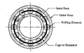
Rolling pair
| Contact between the pair elements is rolling. DOF = 1 |
|
Spherical pair |
When one element in the form of a sphere turns about the other fixed element, it forms a spherical pair. DOF = 3 |
|
Helical/screw pair | In this kind of pair one element turns about the other element through the screw threads present in it. DOF = 1 |
|
Based on nature of contact between elements:
Name of kinematic pair | Description | Diagram |
Lower pair | If the joint by which two members are connected has surface contact, the pair is known as a lower pair. |
|
Higher pair | If the contact between the pairing elements takes place at a point or along a line, it is known as a higher pair. |
|
Based on the nature of mechanical constraint:
Name of kinematic pair | Description | Diagram |
Closed pair | Elements of pairs held together mechanically due to their geometry constitute a closed pair. |
|
Unclosed/force closed pair | Elements of pairs held together by the action of external forces constitute unclosed or force closed pairs. |
|
A free rigid body getting area will describe the subsequent freelance motions. change of location motions on any 3 reciprocally perpendicular axes x, y, and z, motility motions on these axes. Thus, a rigid body possesses six degrees of freedom. The association of a link with another imposes bound constraints on their relative motion. the number of restraints will ne'er be zero (the joint is disconnected) or six (joint becomes solid). Degrees of freedom of a try is outlined because of the variety of freelance relative motions, each change of location and motility, a try will have.
Degrees of freedom = 6 – no. of restraints. To find the number of degrees of freedom for a plane mechanism we've Associate in Nursing equation referred to as Grubler’s equation and is given by,
F = 3 (n – 1) – 2j1– j2
F = quality or a variety of degrees of freedom n = variety of links as well as the frame.
J1 = Joints with a single (one) degree of freedom. J2= Joints with 2 degrees of freedom. If F > 0, results in a mechanism with ‘F’ degrees of freedom. F = 0, leads to a statically determinate structure. F < 0, leads to a statically indeterminate structure. By taking the Associate in Nursing example of figure one.10, we can calculate the degrees of freedom simply. By the higher than given formula, F= 3(5-1)- 2*5= 2. So, there square measure two degrees of freedom within the mechanism shown in the figure.
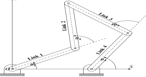
Figure. Five Bar Mechanism
Key Takeaways:
Degrees of freedom, Grubler’s equation F = 3 (n – 1) – 2j 1 – j 2, structure variety by degrees of freedom.
Each half of a machine that moves relative to another part, is thought of as a kinematic link (or merely link) or component. A link could include many elements that square measure bolt fixed along, so that they are doing not move relative to at least one another. for instance, during a reciprocator external-combustion engine as shown in the figure.1.1 piston, connecting rod, and crosshead represent one link; a rod with huge and little finish bearing represent a second link; crank, rotating shaft and regulator as the third link and also the cylinder engine frame and main bearings as the fourth link.
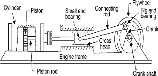
Figure. Reciprocating Steam Engine
A link or component needn't be a rigid body; however, it should be a resistant body. A body is claimed to be a resistant body if it's capable of transmitting the desired forces with negligible deformation. Thus, a link ought to have the following deformation ought to have following 2 characteristics:
Key Takeaways:
Concept of link, relative movement of link, the reciprocating steam engine, characteristics of deformation.
There square measure essentially four styles of the link that are:
1. Rigid Link
2. Versatile link
3. Fluid Link
4. Floating Link
2. Versatile Link: a versatile link is one that whereas transmission motion is part misshapen during a manner to not affect the transmission of motion. for instance, spring, chain, rope, belt, etc.
3. Fluid Link: A fluid link is one that's misshapen by having a fluid during a closed vessel and also the motion is transmitted through the fluid by pressure. for instance, press and hydraulic jack.
4. Floating Link: A floating link is one that's not connected to the frame.
A link can also be classified based upon its number and its end vertices:
Key Takeaways:
Link types and their description
Binary Joint: If 2 links are joined at an equivalent connection; it's known as a binary joint. as an example.
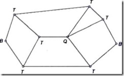
Ternary Joint: If 3 links square measure joined at an affiliation, it's called a ternary joint. it's thought-about admire 2 binary joints since fixing of anybody link constitutes 2 binary joints with every of the opposite 2 links. In Fig. 1.6 ternary links square measure mentioned as T.
Fig.
Quaternary Joint: If four links are joined at an association, it's referred to as a quaternary joint. It thought-about corresponding to 3 binary joints since the fixing of anybody link constitutes 3 binary joints. Figure 1.6 shows one quaternary joint.
In general, if ‘n’ variety of links are connected at a joint, it's corresponding to (n-1) binary joints.
Key Takeaways:
Types of joints, binary, ternary and quaternary joints.
The 2 links or parts of a machine, once in grips with one another, square measure aforesaid to create a pair. If the relative motion between them is totally or with success forced the pair is thought of as kinematic pair.
Classification of pair is based on:
Sliding Pair: The 2 parts have a slippy motion relative to every alternative. Example: Piston and cylinder try rectangular rod is a rectangular line.
Turning Pair: Once the 2 parts square measure connected such the component revolves around the opposite component. Example: Shaft rotates within the bearing rotation of a crank during a slider-crank mechanism.
Rolling pair: once one component is absolved to roll on another component. Example: The belt and simple machine surfaces represent a rolling try.
Screw Pair: During this sort the contacting surface has threads. it's additionally known as a whorled try one component turns concerning another component by suggests that of thread solely. Example: A bolt and nut arrangement jack for lifting serious weights.
Spherical Pair: One component is within the type of sphere and turns concerning the fastened element; Example: ball and socket joint
2. In step with the sort of contact between the weather.
Lower Pair: If a try motion has surface contact between the weather. Example: Piston reciprocatory during a cylinder Shaft rotates during a bearing. (Contacting surfaces square measure similar)
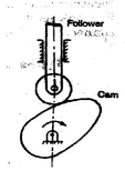
Higher Pair: In higher try, there's a line or purpose contact between the weather.
Example: Cam and follower. (Contact surfaces square measure differently.)
3. In step with the sort of closure.
Self-Closed Pair: In this pair, two elements are held together mechanically; Example: All lower pair
Unclosed Pair/Force Closed Pair: The two elements are not held together mechanically; Example: Cam and followers.
Key Takeaways:
Kinematic pairs and their types, lower pair, higher pair, screw pair, turning pair and to know the exact similarity and difference between the two.
When the kinematic pairs square measure coupled in such a way that the last link is joined to the primary link to transmit definite motion (i.e., utterly or with success affected motion) it is known as a kinematic chain. In alternative words, is also outlined as a mixture of kinematic pairs, joined in such the way that every link forms a neighbourhood of 2 pairs and therefore the relative motion between the links or parts is totally or with success affected motion.
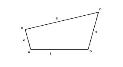
Figure. Kinematic Chain
When the kinematic pairs square measure coupled in such a way that the last link is joined to the primary link to transmit definite motion (i.e., utterly or with success affected motion) it's known as a kinematic chain. In alternative words, is also outlined as a mixture of kinematic pairs, joined in such the way that every link forms a neighbourhood of 2 pairs and therefore the relative motion between the links or parts is totally or with success affected motion.
If every link is assumed to make 2 pairs with 2 adjacent links, then the relation between range the amount the quantity} of pairs (p) forming a kinematic chain and also the number of links (l) is also expressed within the style of associate degree equation:
l=2p-4
During a kinematic chain, every link forms a district of 2 pairs. Another relation between range the amount the quantity of links (l) and also the number of joints (j) that represent a kinematic chain is given by the expression:
j= 3/ (2l -2)
If within the example,
L.H.S > R.H.S, then it's thought-about as a barred chain
L.H.S = R.H.S, then it's thought-about mutually D.O.F
L.H.S < R.H.S, then it's thought-about as free Chain
Key Takeaways:
Kinematic chain, the formula of kinematic chain l=2p-4, the formula for the expression of joints, j= 3/ (2l -2)
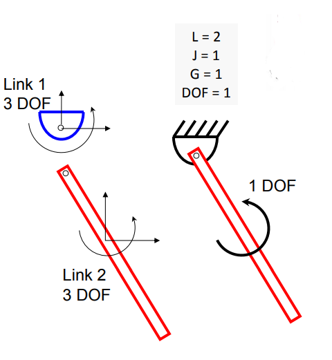
Gruebler’s equation can be used to determine the mobility of planar mechanisms
Gruebler’s Equation
DOF = Mobility
L = Number of links
J = Number of revolute joints or prismatic joints
G = Number of grounded links

1.8 Inversion of mechanism
a) Kinematic inversion of 4 bar chain
b) Slider crank chain or singe slider crank chain
c) Double slider crank chain
Key Takeaways:
Inversion of mechanisms, types of inversions.
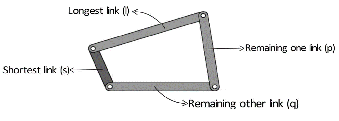
Consider a four-bar mechanism as shown in the following figure:
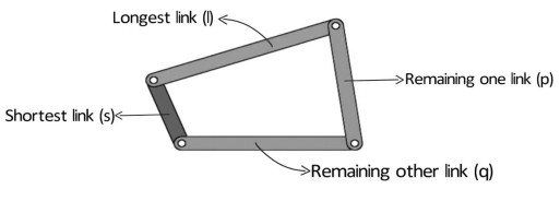
Figure. Grashof’s Law
s= shortest link
l= Longest link
p and q length of the other two links
By Grashof’s law, for at least one link to be capable of making a full revolution, the sum of the lengths of the shortest link and the largest link is less than or equal to the sum of the lengths of the other two links.
s + l ≤ p + q
The condition can be broken into two parts:
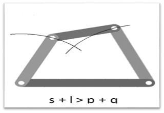
What happens if s+l > p+q?
For s+l>p+q, no link will be able to make a complete revolution, the mechanism so obtained is the triple rocker mechanism.

Figure. Triple Rocker Mechanism
In the triple rocker mechanism, one link is fixed while the other three oscillate.
Now, let us discuss the grashof condition. We broke the condition into two parts:
Case 1: The shortest link is adjacent to the first link.
The mechanism so obtained is the crank rocker mechanism.
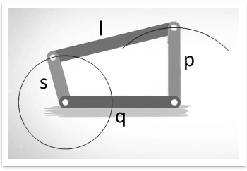
Figure. Crank Rocker Mechanism
In the crank rocker mechanism, the shortest link rotates fully while the other link pivoted to the fixed link oscillates.
Case 2: The shortest link is the fixed link.
The mechanism obtained in this case is known as a double crank mechanism.
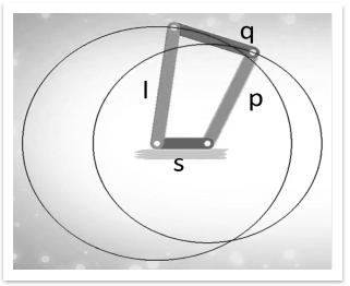
Figure. Double Crank Mechanism
In the double crank mechanism, both the links pivoted to the fixed link rotates fully.
Case 3: The shortest link is opposite to the fixed link
The mechanism obtained in this case is the double rocker mechanism.

Figure. Double Rocker Mechanism
In the double rocker mechanism, both the links pivoted to the fixed link oscillate. The shortest link, which is the coupler, makes a full revolution.
2. s+l = p+q
Case 1: The length of the link is distinct.
Example: ‘s’ is 1 unit, ‘l’ is 4 units, ‘p’ is 2 units and q is 3 units. In this case, s+l= p+q= 5 units. In this case, all the inversions obtained are the same as in the case ‘s+l=p+q’= 5 units. In this case, all the inversions obtained are the same as in the case ‘s+l < p+q’.
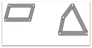
Case 2: The length of the two links is the same.
Example: p=s=1 unit and l= 4 units. Now for ‘s+l= p+q’, q=l= 4 units. So we have two pair of equal length.
In this way link can be joined in two ways :
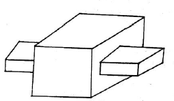
Figure. Parallelogram and Deltoid linkage
All the inversions are either crank rocker or double crank for this case.
Key Takeaways:
Grashof’s law, forumla= s + l ≤ p + q, double crank mechanism, double rocker mechanism, crank rocker mechanism, and all its conditions.
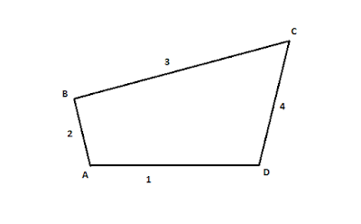
The kinematic chain may be a combination of 4 or additional kinematic pairs, specifying the relative motion between the links or components is unnatural. the best and therefore the basic kinematic chain may be a four-bar chain or curve cycle chain as shown in fig.1.18. It consists of 4 links, each of them forms a turning try at A, B, C, D. The four links are also of various lengths. currently, the speculation, of Grashof’s law clearly applies up here.
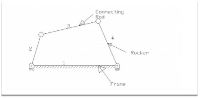
Figure. Four bar chain
A very vital thought in planning a mechanism is to make sure that the input crank makes a whole revolution relative to the opposite links. The mechanism during which no link makes a whole revolution won't be helpful. during a four-bar chain, one in each of the links especially the shortest link can create a whole revolution relative to the opposite 3 links, if it satisfies Grashof’s law. Such a link is understood as a crank or driver. In fig.1.18 (link 2) could be a crank. The link four makes a partial rotation or oscillates is understood as lever or rocker or follower and therefore the link three that connects crank and lever is named rod or coupling. The mounted link one is understood as a frame of the mechanism. once the crank is that the driver, the mechanism is reworking moves into periodical motion.
Inversions of four Bar Chain
Though there are many inversions of the four-bar chain, yet the following are important from the subject point of view:
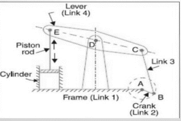
A part of the mechanism of a beam engineer (additionally called crank and lever mechanisms) that consists of 4 links, is shown in figure.1.19 during this mechanism once the crank rotates regarding the fastened center A the lever oscillates regarding the fastened center. the top E of the lever CDE is connected to a connecting rod that reciprocates because of the rotation of the crank. In alternative words, this mechanism aims to convert motility into mutual motion.
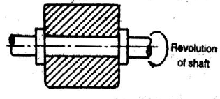
Figure. Beam Engine
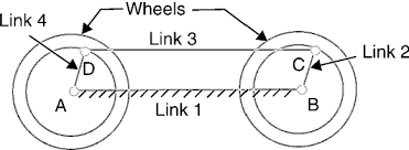
2. Coupling rod of a locomotive ( Double crank Mechanism)
The mechanism of a coupling rod of a locomotive (additionally referred to as double crank mechanism) consists of 4 links as shown in figure.1.20. during this mechanism, the link AD and BC (having equal length) act as cranks and area unit connected to the several wheels. The link CD acts because the coupling rod and therefore the link AB is fastened to keep up a relentless center-to-center distance between them. This mechanism is supposed for sending rotation from one wheel to a different wheel.
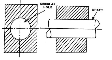
Figure. Coupling rod of a locomotive
3. Watt’s indicator mechanism (Double lever mechanism)
A watt’s indicator mechanism (conjointly called Watt’s line mechanism or double lever mechanism) consists of 4 links as shown in figure.1.21. The four links are fastened link at A, link metal, and link BFD. it should be noted BF and FD kind one link as a result of these 2 components don't have any relative motion between them. The link metal and BFD act as levers. The displacement of the link BFD act as levers. The displacement of the link BFD is directly proportional to the pressure of gas or steam that acts on the indicator plunger. On any little displacement of the mechanism, the tracer, the tracing purpose E at the tip of the link CF, traces at the tip of the link CF traces out more or less a line. The initial position of the mechanism is shown in figure.1.21 by full lines whereas the dotted lines show the position of the mechanism once the gas or steam pressure acts on the indicator plunger.
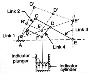
Figure. Watt’s Indicator Mechanism
Key Takeaways:
Four bar chain and its inversions, beam engine, coupling rod of a locomotive, watt’s indicator mechanism.
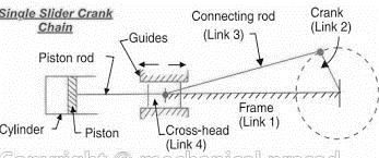
A single slider crank chain may be a modification of the fundamental four bar chain. It accommodates one slippery try and 3 turning pairs. it's typically found in a mutual external-combustion engine mechanism. this sort of mechanism converts motility into mutual motion and the other way around. during a single slider crank chain as shown in figure.1.22. the links one and a pair of, links a pair of and three, and links three and four type 3 turning pairs whereas link four and one forms a slippery pair. Link one corresponds to the frame of the engine, which is fastened. The link a pair of corresponds to the crank; link three corresponds to the rod and link corresponds to the crosshead. because the crank rotates, the crosshead reciprocates within the guides and so the piston reciprocates within the cylinder.
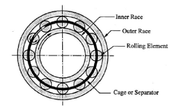
Figure. Single Slider Crank Chain
Inversions of Single Slider Crank Chain
We have seen within the previous article that one slider crank chain may be a four-link mechanism. we all know that by fixing, successively totally different links in an exceedingly kinematic chain, associate degree inversion is obtained and that we will obtain several mechanisms because of the links in an exceedingly kinematic chain. it's therefore obvious, that four bar inversions of one slider crank chain square measure doable. These inversions square measure found within the following mechanisms.
1. Pendulum pump or Bull Engine
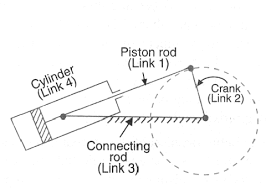
In this mechanism, the inversion is obtained by fixing the cylinder or link four (i.e., slippy pair) as shown in fig.1.23. during this case, once the crank (link 2) rotates, the rod (link 3) oscillates a couple of pins pivoted to the fastened link four at A and therefore the piston hooked up to the connecting rod (link 1) reciprocates. The duplex pump that is employed to produce feed water to boilers has 2 pistons hooked up to link one, as shown in fig.1.23.
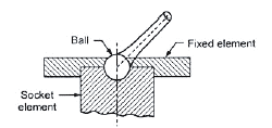
Figure. Pendulum Pump
2. Oscillating Cylinder Engine
The arrangement of oscillatory cylinder engine mechanism as shown in fig.1.24 is employed to convert reciprocal motion into motion. during this mechanism, the link three forming the turning try is fastened. Link three corresponds to the rod of a reciprocal external-combustion engine mechanism. once the crank (link 2) reciprocates and therefore the cylinder (link 4) oscillates concerning the pin pivoted to the fastened link at A.
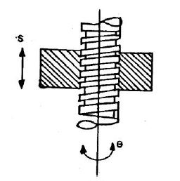
Figure. Oscillating Cylinder Engine
3. Rotary Internal Combustion Engine
Sometimes back, rotary burning engines were employed in aviation. however today turbine area unit employed in its place. It consists of seven cylinders in one plane and everyone revolves regarding fastened center D, as shown in fig.1.25 whereas the crank (link 2) is fastened. during this mechanism, once the rod (link 4) rotates, the piston (link 3) reciprocates within the cylinder forming link one.
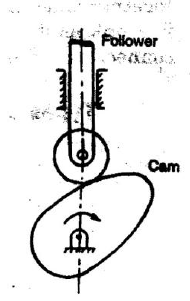
Figure. Rotary Internal Combustion Engine
4. Crank and Slotted Lever Mechanism
This mechanism is generally employed in shaping machines, slotting machines, and rotary burning engines. during this mechanism, the link AC (i.e., link 3) forming the turning try is fastened, as shown in fig.1.26. Link three corresponds to the rod of a reciprocal external-combustion engine. The driving crank CB revolves with uniform angular speed regarding the fastened center C. A slippy block connected to the crankpin at B slides on the slotted bar AP and so causes AP to oscillate regarding the pivoted purpose A. a brief link PR transmits the motion from AP to the ram that carries the tool and reciprocates on the road of stroke R1R2. the road of stroke of the ram (i.e., R1R2) is perpendicular to AC made.
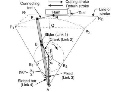
Figure. Crank and Slotted Lever Quick Return Mechanism
In the extreme position, AP1 and AP2 area unit tangential to the circle and therefore the cutlery is at the top of the stroke. The forward or cutting stroke happens once the crank rotates from the position CB1 to CB2 (or through associate angle β) within the dextrorotatory direction. Since the crank has uniform angular speed, therefore,
Since the tool travels a distance of R1R2 during cutting and return stroke, therefore travel of the tool or length of stroke
= R1R2 = P1P2 = 2P1Q = 2AP1 sin(P1AQ)
= 2 AP1 sin (90 – α/2) = 2 AP cos α/2
= 2 AP cos α/2
= 2 AP × 
5. Whitworth Quick Return Motion Mechanism
This mechanism is generally employed in shaping and slotting mechanism. during this mechanism, the link CD (link 2) forming the turning try is fastened. As shown in figure. The link a pair of corresponds to a crank during a reciprocatory external-combustion engine. The driving crank CA (link 3) rotates at a homogenous angular speed. The slider (link 4) hooked up to the crankpin at A slides on the slotted bar PA (link 1) that oscillates at a pivoted purpose D. The rod PR carries the ram at R to that a cutting implement is fastened. The motion of the tool is forced on the road RD made i.e., on a line passing through D and perpendicular to CD.
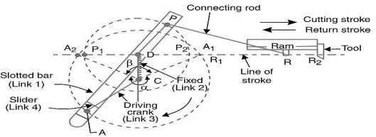
Figure. Whitworth quick return motion mechanism
A little thought can show that the time taken throughout the left to right movement of the ram (i.e., throughout forward or cutting stroke) is quite the time taken throughout the comeback stroke). In different words, the mean speed of the ram throughout the cutting stroke is a smaller amount than the mean speed of the ram throughout the cutting and come backstroke is given by,
 =
=  =
= 
Key Takeaways:
Inversions of single slider crank chain and its types, crank and slotted lever mechanism, pendulum pump, oscillating cylinder engine, rotary combustion engine, Whitworth quick return mechanism, the ratio of time of cutting and return stroke in metal cutting for quick return mechanisms.
Inversions of Double Slider Crank Chain
It is an Associate in Nursing instrument used for drawing ellipses. This inversion is obtained by fixing the slotted plate (link 4) as shown in fig.1.28. The fastened plate or link four has 2 straight grooves cut in it, at right angles to every difference. Link one and link three square measure referred to as sliders and type slippery pairs with link four. The link AB (link 2) may be a bar that forms turning combine with links one and three. When the links one and three slides on their grooves, Associate in Nursing purpose on the link a pair of like P traces out an oval on the surface of link four, as shown as fig.1.28. a bit of thought can show that AP and BP square measure the semi-major and semi-axis of the oval severally. this could be proved as follows:
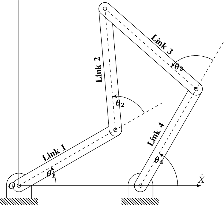
Figure. Elliptical Trammels
x= PQ = AP cos  and y= PR = BP sin
 = cos
= cos ;
;  = sin
= sin 
Squaring and adding both sides,
 +
+  =1
=1
Hence traced by point P is an ellipse.
2. Scotch Yoke Mechanism
This mechanism is employed for changing movement into reciprocatory motion. The inversion is obtained by fixing either link one or link three. In fig1.29 link one is mounted whereas link two (which corresponds to the crank) rotates regarding B as center, the link four (which corresponds to a frame) reciprocates. The mounted link guides the frame.
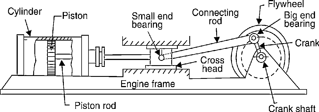
Figure. Scotch Yoke Mechanism
3. Oldham’s Coupling
An Oldham’s coupling is employed for connecting 2 parallel shafts whose axes are at a little distance apart. The shafts are coupled in such a way that if one shaft rotates, the opposite shaft conjointly rotates at an identical speed. The inversion is obtained by fixing link two as shown in fig.1.29 (a). The shafts to be connected have 2 flanges (link one and link 3) stiffly mounted at either end by formation. Link one and link three types turning combine with link two. These flanges have diametrical slots cut in their inner faces as shown in fig.1.30(c). The tongues on link four closely match into {the 2} slots within the two flanges (link one and link 3). Link four will slide or reciprocate within the slots within the flanges. When the driving shaft A is turned, projection C (link 1) causes the intermediate piece (link 4) to rotate at an identical angle through that projection is turned and it rotates the projection D speed at each instant.

(a) (b) (c)
Figure. Oldham’s Coupling
Key Takeaways:
Double slider crank chain and its inversions, Elliptical trammels, scotch yoke
the mechanism, Oldham's coupling.
As a mechanism moves over a range of motion its geometry changes. If we are using a mechanism to transmit torque, or force then we must consider the ratio between the input and output force in various positions.
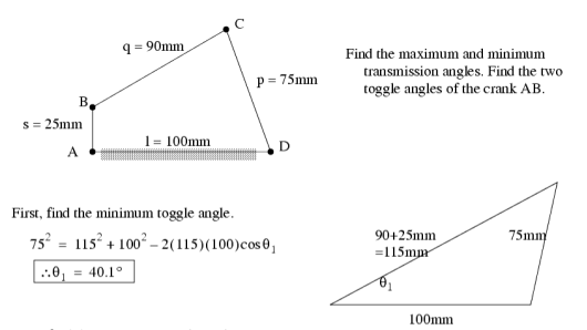
Transmission angle is the angle between the coupling member and the output member in a mechanism. As this angle approaches ±90°, the mechanical advantage of the mechanism typically increases.
Toggle positions occur when the input crank has near infinite mechanical advantage. Note: this also applies that the follower has no mechanical advantage on the crank.
1.14 Mechanical advantage
The mechanical advantage of a mechanism is the ratio of output force or torque to the input force or torque at any instant Thus for the linkage of fig if friction and inertia force are ignored and the input torque T2 is applied to link 2 to drive the output link 4 with resisting torque t4 drive the output 4 with resisting torque T4 then
Power input = power output
T4 – T4
– T4 
 =
=
Thus, it is reciprocal of the velocity ratio.in case of crank rocker mechanisms the velocity w4 of the output link DC become zero at the extreme case of crank rocker mechanisms the velocity  4 if the output link AB is in with couple BC and the angle
  between them is either zero or 180
 it makes the mechanical advantage to be infinite at such position.
1.15 Kinematic Analysis: Graphical analysis of position
When the body moves with uniform velocity. When the body moves with uniform velocity, equal distances are covered in equal intervals of time. By plotting the distances on Y-axis and time on X-axis, a displacement-time curve (i.e., s-t curve) is drawn which is a straight line, as shown in Fig. 2.1 (a). The motion of the body is governed by the equation s = u.t, such that
Velocity at instant 1 = s1 / t 1
Velocity at instant 2 = s 2 / t 2
Since the velocity is uniform, therefor

where tan θ is called the slope of s-t curve. In other words, the slope of the s-t curve at any instant gives the velocity.
3. When the body moves with variable velocity. When the body moves with variable velocity, unequal distances are covered in equal intervals of time or equal distances are covered in unequal intervals of time. Thus, the displacement-time graph, for such a case, will be a curve, as shown in Fig. 2.1 (b).
Consider a point P on the s-t curve and let this point travels to Q by a small distance δs in a small interval of time δt. Let the chord joining the points P and Q makes an angle θ with the horizontal. The average velocity of the moving point during the interval PQ is given by

In the limit, when δt approaches to zero, the point Q will tend to approach P and the chord PQ becomes tangent to the curve at point P. Thus, the velocity at P,
where tan θ is the slope of the tangent at P. Thus, the slope of the tangent at any instant
 on the s-t curve gives the velocity at that instant.
Velocity and Acceleration by Complex Algebra Method
Using the slider-crank of Fig. 2.6. once more as an illustration with an x-axis along the
the centreline of the guide, and recalling that i^2=-1, we write the complex-number
equations as follows, with the equivalent vector equation below each:
Displacement: ae^i a + be^i
 b+ce^i
 c=x ……. (1)
AB + BD + DC = AC …… (2)
Velocity: iae^ iawAB + (ibe^i
 b + ice^ic) +BC = dx/dt …. (3)
VB +VD/B +VC/D=VC……... (4)
Note that wAB =d a/dt is positive when counter-clockwise and negative when clockwise; in this problem wAB is negative.
The complex conjugate of Eq. (3)

From Eqs. (3) and (4), regarded as simultaneous equations:


The quantities a, b, c square measure obtained from a scale drawing or by trig. Both the vector-polygon and therefore the complex-number ways is without delay extended to accelerations, additionally the} latter also to the upper accelerations.
Differentiating equation 3 we get,

This is equivalent to the vector equation:

Combining the above equation and its complex conjugate, eliminate d^2x/dt^2 and solve for  BC in the following equation for AD:

The higher than complex-number approach conjointly lends itself to the analysis of motions involving Coriolis acceleration. The latter is encountered within the determination of the relative acceleration of 2 outright coincident points on totally different links.
Velocity and Acceleration Analysis by Vector Method
The method is illustrated using a point D on the connecting rod of a slider-crank
mechanism (Fig. 2.5). The vector-velocity equation for C is

Where VB = velocity of B

Where Vc= velocity of C
Vb= velocity of B
 normal component of velocity of C relative to B = component of relative velocity along BC = zero (owing to the rigidity of the connecting rod)
 component of velocity of C relative to B, value
  perpendicular to BC
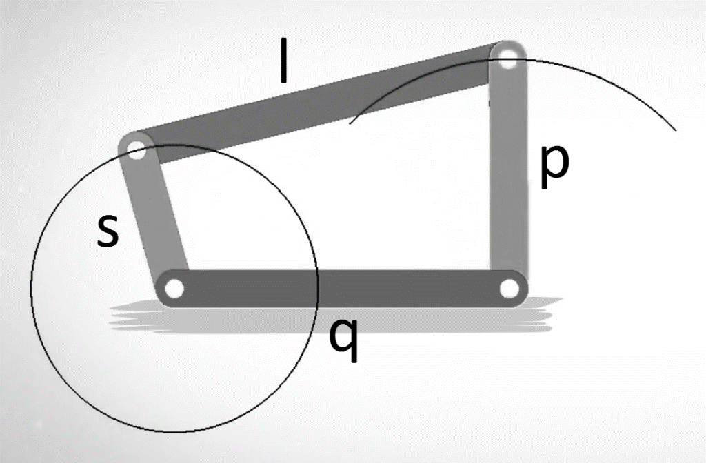
Figure. Velocity – Vector Diagram
We continue with the slider-crank of Fig. 2.5. After solving for the velocities via the
velocity polygon, write out and “draw” the acceleration equations. Again, proceed in order of increasing difficulty: from B to C to D, and determine first the acceleration of point C:

 acceleration normal to path of C(equal to zero in this case)
 acceleration parallel to path of C
 acceleration normal to path of B, value
  direction B to A
 acceleration parallel to path of B, value
  sense determined by that
of  (where
 acceleration component of C relative to B, in the direction C to B, value

 acceleration component of C relative to B,
 value of
  Since
Since
 is unknown, so is the magnitude and sense of
Now, we can draw the acceleration diagram,
1. Choose an arbitrary origin o, as before.
2. Draw each acceleration of scale ka (inch per second squared), and label the appropriate vector terminals with the lowercase letter corresponding
to the point whose acceleration is designated, e.g., AB = (ob)/ka.
Draw ABn, ABt, Ac/B.
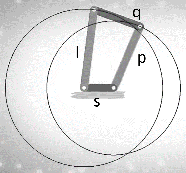
Figure. Acceleration vector Diagram
Key Takeaways:
Velocity and acceleration analysis of slider-crank chain mechanism by complex
algebra method and vector method, calculation, and analysis, understanding of
concepts.
Instantaneous center can be defined as a point about which link can be considered to be rotating at a given instant. Such a center has zero velocity, i.e., the link is at rest at this point. This center varies from instant to instant for different positions of the link. The locus of these centers is termed the centrode. Number of instantaneous centers for a mechanism can be calculated as follows:

Where N is the number of instantaneous centers and n be the number of links in the mechanism.
Properties of Instantaneous Center
Types of Instantaneous Centers
There are three types of instantaneous centers for any mechanism. Figure 6 illustrates all the types of instantaneous centers, in which the instantaneous centers 12 and 14 does not move from its position because one link among the two links for the given instantaneous center is fixed, hence these instantaneous centers are termed as the fixed instantaneous centers.
Instantaneous centers 23 and 34 always remains at the at the intersection of the given links hence they may change their position as the links moves but their position on the links is permanent hence, these instantaneous centers are known as permanent instantaneous centers.
Instantaneous centers 13 and 24 changes their position in space with the configuration of mechanism and they also do not lie on any permanent position on the links, hence they are neither permanent nor fixed.
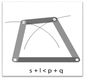
Figure. Instanteneous centers of four bar mechanism
Location Instantaneous Centers
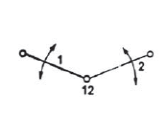
According to the definition instantaneous center is the point where the relative velocity of the two points on a body is zero. Hence, in order to locate instantaneous center, we draw perpendicular at these points from the direction of their motion and the intersection point of these lines gives the instantaneous center as shown in figure 7(a). To locate instantaneous centers for a mechanism following observation are helpful:
(a) (b) (c)

(d) (e) (f)
Figure. Location of instantaneous center for various cases
According this theorem instantaneous centers of three -plane bodies in relative motion to each other must be co-linear.
Let us consider three links 1,2 and 3 as shown in figure 8. In the given diagram link 1 is fixed while links 2 and 3 are movable. Instantaneous center of link 1,2 and 1,3 lies on the pin joint at 12 and 13 as shown in figure 8. Now let us consider the instantaneous center for the link 2 and 3 in not co-linear to 12 and 13. In this case point 23 have two different direction of motion which is not possible. The one direction of motion for the point 23 is possible only if it is colinear to 12 and 13. That is what Kennedy’s theorem says.
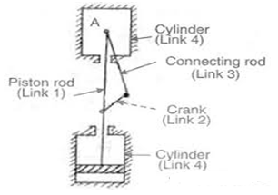
Figure. Proving Kennedy theorem
The links in a mechanism are mostly connected by means of pin joints. The rubbing velocity is defined as the algebraic sum between the angular velocities of the two links which are connected by pin joints, multiplied by the radius of the pin.
Consider two links OA and OB connected by a pin joint at O as shown in Fig. 7.6.
Let ω1 = Angular velocity of the link OA or the angular velocity of the point A with respect to O.
ω2 = Angular velocity of the link OB or the angular velocity of the point B with respect to O, and
r = Radius of the pin.
According to the definition, Rubbing velocity at the pin joint
O = (ω1 – ω2) r, if the links move in the same direction
= (ω1 + ω2) r, if the links move in the opposite direction
Note: When the pin connects one sliding member and the other turning member, the angular velocity of the sliding member is zero. In such cases,
Rubbing velocity at the pin joint = ω.r where
ω = Angular velocity of the turning member, and
r = Radius of the pin
If the body moves in a fixed frame or with respect to a fixed body it has two components of acceleration i.e., centripetal and tangential component, and we use above analysis to obtain the acceleration. When a body moves in moving frame or with respect to a body which is moving itself such as motion of slider on a rotating link, we use following analysis to calculate its acceleration.
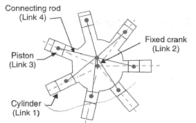
Fig. Motion of slider on a rotating link
Let us consider slider represented by Q slides with velocity v over a rotating link AR which rotates with an angular velocity in clockwise direction and have an angular acceleration of in clockwise direction at the given instant.
Let us take a point P on the slider to analyses the motion of slider on the link AR. It is assumed that f is the linear acceleration of slider on the link AR and r is the radial distance of point P.
Now acceleration of point P parallel to AR is given by:

In this case the slider is having acceleration radially outward direction hence taken positive, it will be negative if slider is accelerated while moving inward of retarded while moving outward.
Similarly, acceleration of P perpendicular to AR is given by:


Here the acceleration of P perpendicular to AR has two components one is the tangential acceleration of AR and the term 2v which is known as the Coriolis component of acceleration.
Coriolis component will always be positive if v and are of same sign i.e., both are either positive or negative. Positive implies the rotation in clockwise direction while positive v is the motion in radially outward direction.
Total acceleration of point P can be obtained by calculating the vector sum of the acceleration of P along the AR vector and perpendicular to the AR vector, which is given by:


Where


References:


