Unit - 2
Gear and Gear Trains
Gear can be defined as the toothed member that is used to transmit the power from one shaft to another shaft. Gear transmits the motion by direct contact. Among the two meshing gears smaller one is known as the pinion while larger one is known as wheel or gear. Gears are broadly classified on the basis of layout of connecting shaft.
Table.1. Classification of Gear
Type of Gear | Layout of shafts |
Spur/Helical | Parallel shafts |
Bevel Gears | Perpendicular Shafts |
Worm Gears | Non-intersecting Perpendicular shafts |
Gear Terminology
Gear terminology is the various terms to study the gear which is being discussed below and figure 1 show the various terms used in gear terminology.
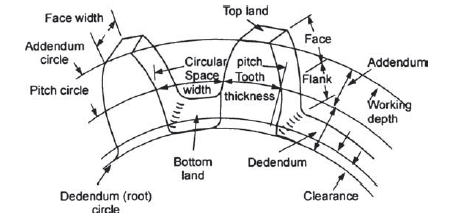
Figure.1. Gear Terminology
Pitch Circle: It is an imaginary circle which transmits the same motion by pure rolling as the transmitted by the gears in mesh.
Pitch Circle Diameter: Diameter of pitch circle is known as the pitch circle diameter.
Circular pitch: Circular pitch is the distance of a point on one tooth to the corresponding point on the adjacent tooth along the pitch circle. It is denoted by the p.

t = number of teeth.
d = pitch circle diameter.
Diametral Pitch: Diametral pitch of a gear is the number of teeth per unit length of pitch circle diameter in inches. It is denoted by P.

Module: it is the ratio of pitch circle diameter in mm to the number of teeth on the gear. it is denoted by m.

Gear Ratio: Gear ratio is the ratio of number of teeth on driven gear to the number of teeth on driving gear. it is denoted by G.

T= number of teeth on driven gear.
t = number of teeth on driving gear.
Velocity ratio: It is the ratio of angular velocity of driven gear to the angular velocity of driving gear. It is denoted by VR.
Let N be the rpm, be the angular velocity and T be the number of teeth on gear. while subscript 1 and 2 are used for the driving and driven gears respectively.

Addendum circle: It is the circle passing through the tip of the gear tooth.
Addendum: It is the height of the gear tooth in radial direction above the pitch circle. Standard value of addendum is one module.
Dedendum Circle: The circle passing through the root of circle is known as the dedendum circle.
Dedendum: It is the depth of gear tooth along the radial direction below the pitch circle. Its standard value is 1.157 modules.
Clearance: It is the difference between the addendum and dedendum of the gear. Standard value of clearance is 0.157m.
Full depth of teeth: It is the total radial depth of the gear tooth. It is calculated by adding the addendum and dedendum of the gear tooth.
Working depth of teeth: It the maximum depth up to which tooth of one gear penetrate in the mating gear. It is calculated by adding the addendum of the mating gears.
Space width: It is the width of space between the two adjacent teeth of a gear along the pitch circle.
Tooth thickness: It is the thickness of the gear tooth measured along the pitch circle.
Backlash: Backlash is defined as the difference between the tooth thickness and the space width.
Face width: It is the width of the gear tooth measured along the axis of gear.
Top land: Top surface of the gear tooth.
Bottom land: The bottom surface of the tooth between the adjacent fillets.
Face: It the surface of tooth between the pitch circle and top land.
Flank: It the surface of tooth between the pitch circle and the bottom land which also includes the fillet.
Line of action: It is the line joining the pitch point to the point of contact of two mating gear along which the driving gear exerts force on the driven gear. It is also known as the pressure line.
Pressure angle: It is the angle between the common tangent to the pitch circle and the line of action. It is also known as angle of obliquity and denoted by .
Path of contact: It is the locus of point of contact of two mating gears from beginning of contact up to disengagement of the gears. It constitutes of following two paths.
Path of approach: It is the locus of point of contact from starting of engagement to pitch point.
Path of recess: It is the locus of point of contact from pitch point to the end of engagement.
Arch of contact: It is the locus of point of contact along pitch circle form beginning of engagement to end of engagement. Just like path of contact it can also be divided in two parts.
Arc of Approach: It is the part of arc of contact from beginning of engagement to pitch point.
Arc of Recess: It is the part of arc of contact from pitch point to end of engagement.
Angle of action: It is the angle turned by the pair of teeth of gears from beginning of engagement to the end of engagement.
Contact ratio: It is the ration of arc of contact to the circular pitch.
Tooth profile 1 drives tooth profile 2 by acting at the instantaneous contact point K.
N1N2 is the common normal of the two profiles.
N1 is the foot of the perpendicular from O1 to N1N2
N2 is the foot of the perpendicular from O2 to N1N2.
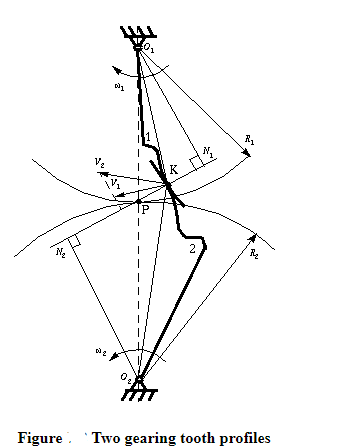
Although the two profiles have different velocities V1 and V2 at point K, their velocities along N1N2 are equal in both magnitude and direction. Otherwise the two tooth profiles would separate from each other. Therefore, we have

or

We notice that the intersection of the tangency N1N2 and the line of center O1O2 is point P, and

Thus, the relationship between the angular velocities of the driving gear to the driven gear, or velocity ratio, of a pair of mating teeth is

Point P is very important to the velocity ratio, and it is called the pitch point. Pitch point divides the line between the line of centers and its position decides the velocity ratio of the two teeth. The above expression is the fundamental law of gear-tooth action.
For a constant velocity ratio, the position of P should remain unchanged. In this case, the motion transmission between two gears is equivalent to the motion transmission between two imagined slip less cylinders with radius R1 and R2 or diameter D1 and D2. We can get two circles whose centers are at O1 and O2, and through pitch point P. These two circles are termed pitch circles. The velocity ratio is equal to the inverse ratio of the diameters of pitch circles. This is the fundamental law of gear-tooth action.
The fundamental law of gear-tooth action may now also be stated as follow (for gears with fixed center distance
The following table shows the standard proportions in module (m) for the four gear systems as discussed in the previous article.
Standard proportions of gear systems
S.No | Particulars |
|
|
|
1. 2. 3. 4. 5. 6. 7. | Addendum Dedendum Working depth Minimum total depth Tooth thickness Minimum clearance Fillet radius at root | 1m 1.25m 2m 2.25m 1.5708m 0.25m 0.4m | 1m 1.25m 2m 2.25m 1.5708m 0.25m 0.4m | 0.8m 1m 1.60m 1.80m 1.5708m 0.2m 0.4m |
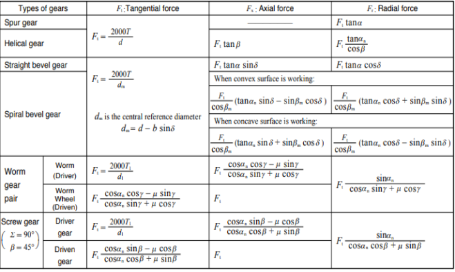
In designing a gear, it is important to analyze the magnitude and direction of the forces acting upon the gear teeth, shafts, bearings, etc. In analyzing these forces, an idealized assumption is made that the tooth forces are acting upon the central part of the tooth flank.
Table 1 presents the equations for tangential (circumferential) force Ft (kgf), axial (thrust) force Fx(kgf), and radial force Fr in relation to the transmission force Fn acting upon the central part of the tooh flank. T and T1 shown therein represent input torque (kgf·m).
Table.1 Forces acting upon a gear
load as 
2.5 Interference and Undercutting
Interference
Locking of meshed gear teeth due non-conjugate or non-involute profile is termed as the interference. Non-conjugate gear teeth profile causes improper sliding of gear teeth which results in rough action and binding. Rough action and binding cause different sliding velocity of mating gears and results in locking.
Minimum number of teeth to avoid interference


Undercutting
In case of involute gear profile addendum of mating gears removes some part in the dedendum if there is interference. This removed portion in the dedendum is known as the undercut and the process of removal of the material from at the root of gears is known as undercutting. Figure 6 shows the undercutting in the gears.
Minimum Number of Teeth on the Pinion in Order to Avoid Interference
Minimum Number of Teeth on the Wheel in Order to Avoid Interference
Minimum Number of Teeth on a Pinion for Involute Rack in Order to Avoid Interference.
We have already discussed in the previous article that in order to avoid interference, the addendum circles for the two mating gears must cut the common tangent to the base circles between the points of tangency. The limiting condition reaches, when the addendum circles of pinion and wheel pass through points N and M (see Fig. 12.13) respectively
t = Number of teeth on the pinion,
T = Number of teeth on the wheel,
m = Module of the teeth, r = Pitch circle radius of pinion = m.t / 2
G = Gear ratio = T / t = R / r
φ = Pressure angle or angle of obliquity
From triangle 


Limiting radius of the pinion addendum circle

AP .m = Addendum of the pinion, where AP is a fraction by which the standard addendum of one module for the pinion should be multiplied in order to avoid interference.
We know that the addendum of the pinion


This equation gives the minimum number of teeth required on the pinion in order to avoid interference.
.2.8 Analysis of mechanism Trains: Simple Train
Gear train is the drive which uses the combination of gears to transmit the motion from one shaft to another shaft. These drives are used where high-speed reduction is required at limited space. Different kinds of gear trains used are:
Simple gear train
A simple gear train is the combination of gears in which only one gear is fixed on one shaft. in these gear trains two mating pairs rotate in opposite direction. If there are more than two gears in the gear train then even number gears rotate in one direction and odd number gears rotate in same direction but opposite to even number gears. Figure 7 shows the arrangement of gears in simple gear train.

Figure.7. Arrangement of gears in simple gear train
In the analysis of a gear train, we try to find out the train value which is defined as the ratio of speed of speed of driven gear to the speed of driving gear. The train value is used to calculate the angular velocity transmitted by the gear train.
For simple gear train shown in figure 7, N represents the angular velocity of each gear followed by its number in subscript, similarly T represents the number of teeth on each gear.
In case of gears in mesh 


By multiplying all the above equations


These are the gear trains in which one shaft contains more than one gears. Consider the gear train shown in figure 8 which shows the arrangement of gears in a compound gear train. In the given compound gear train gear 1 is driving gear, gear 2 and 3 are mounted on same shaft.
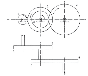
Figure.8. Compound gear train
For the given gear train

Multiplying all the above equations


These are the gear train are special types of compound gear trains, in which axis of first and last gears are same. These kind of gear trains are used in clocks. Figure 9 shows the reverted gear train in which the axis of 1st and 4th gear are coinciding while gear 2 and 3 comprises a compound gear.
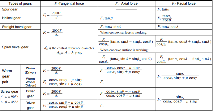
Figure.9. Reverted gear train
For the gear train shown in figure 9

Multiplying all the above equations


And
2.11 Epicyclic train and their applications
Apart from rotation of gears if any gear axis is also rotating with respect to some other axis the gear train is termed as epicyclic gear train. To rotate the axis of gear a very important link is used which is known as arm or carrier which is not gear.
The epicyclic great train shown in figure 10 has gears S and P and the arm a. The gear S and P are in mesh are rotating about their own axis with the help on arm a, axis of both the gear are rotating with respect to axis of each other. The degree of freedom for the epicyclic gear train is 2.
Consider the number of teeth on S and P gears are Ts and Tp respectively. In order to analyze the epicyclic gear train shown in figure 10 let us assume clockwise rotation is taken as positive and counter clockwise rotation as negative and now follow the given steps and prepare the table 1 shown below.


3. Now multiply the rpm of each component by x.
4. At last, add the rpm of arm which is assumed to be y.
5. Then put the rpm of each component equal to the condition given in question and solve the problem accordingly.
Table.1. Analysis table for epicyclic gear train
Operation | RPM | ||
Arm a | Gear S | Gear P | |
Arm a is fixed Gear S +1 Revolution | 0 | +1 |
|
Multiply by x | 0 | x |
|
Add y | +y | x+y |
|
Now substitute the rpms of given component according the condition given in question and solve.
References:


