Unit - 3
Combined Static and Inertia Force Analysis
In plane motions involving accelerations, the inertia force acts on a body through its centre of mass. However, if the body is acted upon by forces such that their resultant does not pass through the centre of mass, a couple also acts on the body. In graphical solutions, it is possible to replace inertia force and inertia couple by an equivalent offset inertia force which can account for both. This is done by displacing the line of action of the inertia force from the centre of mass. The perpendicular displacement h of the force from the centre of mass is such that the torque so produced is equal to the inertia couple acting on the body,


A slider crank mechanism is shown in Fig. 8.3 (a). Let the crank OB makes an angle θ with the inner dead centre (I.D.C) and rotates in a clockwise direction about the fixed-point O with uniform angular velocity ωBO rad/s. ∴ Velocity of B with respect to O or velocity of B (because O is a fixed point
 acting tangentially at B.
We know that centripetal or radial acceleration of B with respect to O or acceleration of B (because O is a fixed point),

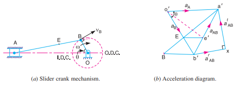
The acceleration diagram, as shown in Fig. (b), may now be drawn as discussed below:
1. Draw vector o' b' parallel to BO and set off equal in magnitude of BO B r a a =, to some suitable scale. 2. From point b', draw vector b'x parallel to B A. The vector b'x represents the radial component of the acceleration of A with respect to B whose magnitude is given by

Since the point B moves with constant angular velocity, therefore there will be no tangential component of the acceleration.
3. From point x, draw vector xa' perpendicular to b'x (or A B). The vector xa' represents the tangential component of the acceleration of A with respect to B i.e., AB. t a Note: When a point moves along a straight line, it has no centripetal or radial component of the acceleration.
4. Since the point A reciprocates along AO, therefore the acceleration must be parallel to velocity. Therefore, from o', draw o' a' parallel to AO, intersecting the vector xa' at a'. Now the acceleration of the piston or the slider A (aA) and AB t a may be measured to the scale.
5. The vector b' a', which is the sum of the vectors b' x and x a', represents the total acceleration of A with respect to B i.e., aAB. The vector b' a' represents the acceleration of the connecting rod A B.
6. The acceleration of any other point on A B such as E may be obtained by dividing the vector b' a' at e' in the same ratio as E divides A B in Fig. 8.3 (a). In other word

7. The angular acceleration of the connecting rod A B may be obtained by dividing the tangential component of the acceleration of A with respect to B () AB t a to the length of A B. In other words, angular acceleration of A B,

An engine is acted upon by various forces such as weight of reciprocating masses and connecting rod, gas forces, forces due to friction and inertia forces due to acceleration and retardation of engine elements, the last being dynamic in nature.
In this section, the analysis is made of the forces neglecting the effect of the weight and the inertia effect of the connecting rod
(i) Piston Effort (Effective Driving Force)
The piston effort is termed as the net or effective force applied on the piston.
In reciprocating engines, the reciprocating masses accelerate during the first half of the stroke and the inertia force tends to resist the same.
Thus, the net force on the piston is decreased.
During the later half of the stroke, the reciprocating masses decelerate and the inertia force opposes this deceleration or acts in the direction of the applied gas pressure and thus, increases the effective force on the piston.
In a vertical engine, the weight of the reciprocating masses assists the piston during the outstroke (down stroke), thus, increasing the piston effort by an amount equal to the weight of the piston.
During the instroke (upstroke), the piston effort is decreased by the same amount.
Let  area of the cover end
 area of the piston rod end
 pressure on the cover end
 pressure on the rod end
 mass of the reciprocating parts
Force on the piston due to gas pressure, 
Inertia Force, 
Which is in the opposite direction to that of the acceleration of the piston.
Net (effective) force on the piston, 
In case friction resistance  is also taken into account,
Force on the piston, 
In case of vertical engines, the weight of the piston or reciprocating parts also acts as force and thus force on the piston, 
The various forces acting on the connecting rod are as follows: Forces on the piston due to gas pressure and inertia of the reciprocating parts.
1. Forces on the piston due to gas pressure and inertia of the reciprocating parts.
2. Force due to inertia of the connecting or inertia bending forces
3. Force due to friction of the piston rings and of the piston, and
4. Forces due to friction of the piston pin bearing and crank pin bearing.
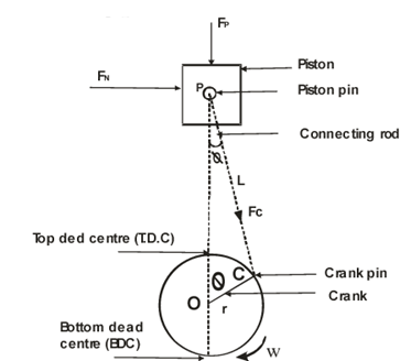
It is known that the force on the piston due to pressure of gas,
FL = Pressure X Area = 
And inertia force of reciprocating parts,
FI = Mass x acceleration = 
It may be noted that the inertia force of reciprocating parts opposes the force on the piston when it moves during its downward strokes (i.e., when the piston moves from the Top dead centre to Bottom dead centre). On the other hand, the inertia force of the reciprocating parts helps the force on the piston when it moves from the Bottom Dead Centre (BDC) to Top Dead Centre (TDC).
: Net force acting on the piston or piston pin (or gudgeon pin or wrist pin)
Fp = Force due to gas pressure ± inertia force = FL ± FI. The negative sign is used when piston moves from Top Dead Centre to Bottom Dead Centre and positive sign used when piston moves from Bottom Dead Centre to Top Dead Centre.
When weight of the reciprocating parts (WR = mR. g) is to be taken in to consideration, then FP = FL ± FI ± WR
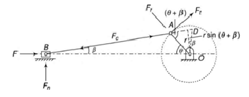
Force is exerted on the crankpin as a result of the force on the piston. Crank efforts is the net effort (Force) applied at the crankpin perpendicular to the crank which gives the required turning moment on ht ecrankshaft.
Let  crank effort


In order to determine the motion of a rigid body, under the action of external forces, it is usually convenient to replace the rigid body by two masses placed at a fixed distance apart, in such a way that,
1. the sum of their masses is equal to the total mass of the body;
2. the centre of gravity of the two masses coincides with that of the body; and
3. the sum of mass moment of inertia of the masses about their centre of gravity is equal to the mass moment of inertia of the body.
When these three conditions are satisfied, then it is said to be an equivalent dynamical system. Consider a rigid body, having its centre of gravity at G, as shown in Fig. Let m = Mass of the body,
kG = Radius of gyration about its centre of gravity G,
m1 and m2 = Two masses which form a dynamical equivalent system
L1 = Distance of mass m1 from G,
l 2 = Distance of mass m2 from G, and
L = Total distance between the masses m1 and m2.
Thus, for the two masses to be dynamically equivalent,


From equations (i) and (ii),


Substituting the value of  and
and  in the equation (iii), we have


This equation gives the essential condition of placing the two masses, so that the system becomes dynamical equivalent. The distance of one of the masses (i.e., either l 1 or l2) is arbitrary chosen and the other distance is obtained from equation (vi). Note: When the radius of gyration kG is not known, then the position of the second mass may be obtained by considering the body as a compound pendulum. We have already discussed, that the length of the simple pendulum which gives the same frequency as the rigid body (i.e., compound pendulum

We also know that 

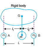
This means that the second mass is situated at the centre of oscillation or percussion of the body, which is at a distance of l 2 = (kG) 2 /l 1.
Consider an extended body of mass M with a hole drilled though it. Suppose that the body is suspended from a fixed peg, which passes through the hole, such that it is free to swing from side to side, as shown in Fig. 98. This setup is known as a compound pendulum.
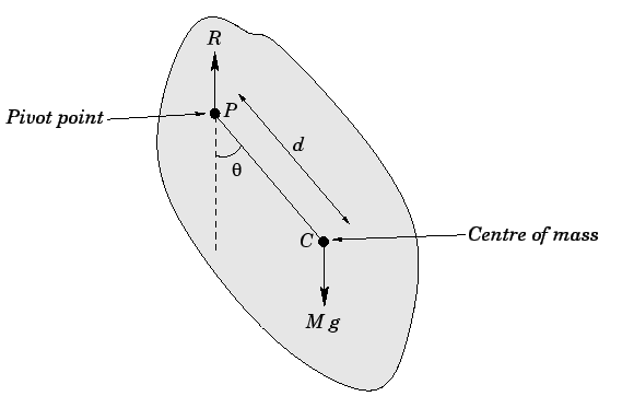
Let  be the pivot point, and let
  be the body's centre of mass, which is located a distance
  from the pivot. Let θ be the angle subtended between the downward vertical (which passes through point
  ) and the line
  . The equilibrium state of the compound pendulum corresponds to the case in which the centre of mass lies vertically below the pivot point: i.e.,
  . See Sect. 10.3. The angular equation of motion of the pendulum is simply

where  is the moment of inertia of the body about the pivot point, and is the torque? Using similar arguments to those employed for the case of the simple pendulum (recalling that all the weight of the pendulum acts at its centre of mass), we can write

Note that the reaction, at the peg does not contribute to the torque, since its line of action passes through the pivot point. Combining the previous two equations, we obtain the following angular equation of motion of the pendulum:

Finally, adopting the small angle approximation,  , we arrive at the simple harmonic equation:

It is clear, by analogy with our previous solutions of such equations, that the angular frequency of small amplitude oscillations of a compound pendulum is given by
It is helpful to define the length


which is identical in form to the corresponding expression for a simple pendulum. We conclude that a compound pendulum behaves like a simple pendulum with effective length  .
.
we have discussed the conditions for equivalent dynamical system of two bodies. A little consideration will show that when two masses are placed arbitrarily*, then the conditions (i) and (ii) as given in Art. 15.11 will only be satisfied. But the condition (iii) is not possible to satisfy. This means that the mass moment of inertia of these two masses placed arbitrarily, will differ than that of mass moment of inertia of the rigid body

Consider two masses, one at A and the other at D be placed arbitrarily, as shown in Fig. 15.21. Let l 3 = Distance of mass placed at D from G, I 1 = New mass moment of inertia of the two masses; k 1 = New radius of gyration; α = Angular acceleration of the body; I = Mass moment of inertia of a dynamically equivalent system; kG = Radius of gyration of a dynamically equivalent system. We know that the torque required to accelerate the body, T = I.α = m (kG ) 2 α ...(i) Similarly, the torque required to accelerate the two-mass system placed arbitrarily, T1 = I 1 .α = m (k 1 ) 2 α ...(ii) ∴ Difference between the torques required to accelerate the two-mass system and the torque required to accelerate the rigid body, T' = T1 –T = m (k 1 ) 2 α – m (kG ) 2 α = m [(k 1 ) 2 – (kG ) 2 ] α ...(iv) The difference of the torques T' is known as correction couple. This couple must be applied, when the masses are placed arbitrarily to make the system dynamical equivalent. This, of course, will satisfy the condition (iii) of Art
We know that  and
and 
 Correction couple,
But 


 = Distance between the two arbitrarily masses, and
L = Distance between the two masses for a true dynamically equivalent system. It is the equivalent length of a simple pendulum when a body is suspended from an axis which passes through the position of mass m, and perpendicular to the plane of rotation of the two-mass system.

References:
