Unit - 3
Design of Keys, Shaft and Couplings
Key is a system detail that is used to attach the transmission shaft to rotating system factors like pulley, tools, sprocket or flywheel.
Keys offer a superb method of transmitting torque among shaft and hub of the mating detail. A slot is machined with inside the shaft or with inside the hub or each to house the key's known as keyway.
Keyway reduces the energy of the shaft because it consequences in pressure attention.
Types of Keys Common sorts of keys are:
1. Sunk keys
2. Saddle keys
3. Tangent keys
4. Round keys
5. Splines
Sunk Keys
A sunk key's a key wherein 1/2 of the thickness of key suits into the keyway with inside the shaft and 1/2 of with inside the keyway of the hub.
The sunk keys are of the subsequent types:
Rectangular sunk key:
It is the best sort of key and has a square cross-segment.
A taper of approximately 1 in one hundred is supplied on its pinnacle side.
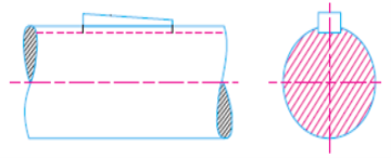
Square sunk key:
Rectangular sunk key having same width and thickness is known as rectangular sunk key.
Parallel sunk key:
If no taper is supplied at the square or rectangular sunk key, its miles known as parallel sunk key i.e. its miles uniform in width and thickness throughout. It is used wherein the pulley, tools or different mating piece is needed to slip alongside the shaft.
Gib-head key:
It is a square sunk key with a head at one quit called gib head that is supplied to facilitate the elimination of key.
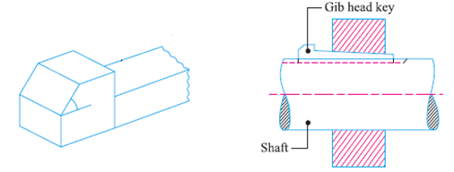
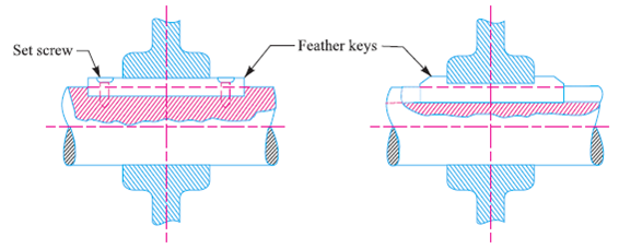
Feather key:
Feather key's a parallel key made as a crucial a part of the shaft with the assist of machining or the usage of set-screws. It allows axial motion and has a sliding suit with inside the key manner of the shifting piece.
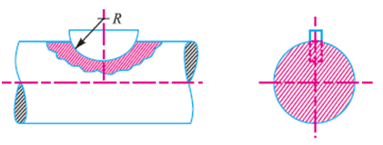
Woodruff key:
Woodruff key's a sunk key with inside the shape of a semicircular disc of uniform thickness. Lower part of the important thing suits into the round keyway of the shaft. It may be used with tapered shafts as it could tilt and align itself at the shaft.
Saddle Keys
Slot for this sort of is supplied best with inside the hub as proven in Figure Torque is transmitted with the aid of using friction best and cannot consequently transmit excessive torque and is used best for mild applications.
The saddle keys are of types:
Flat Saddle Key and Hollow Saddle Key.
In flat saddle key, the lowest floor touching the shaft is flat and it sits at the flat floor machined at the shaft. Hollow saddle key has a concave floor at the lowest to suit the ground floor of the shaft. Chances of slip in case of the flat saddle key are surprisingly lesser and may transmit greater electricity than the whole saddle key.
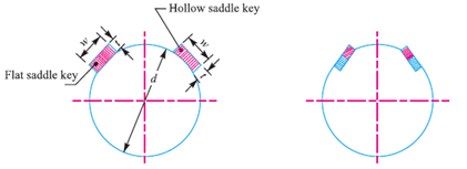
Tangent Keys
Tangent keys are proven in Figure
These are used to transmit excessive torque. They can be used as an unmarried key or a couple at proper angles. Single tangent key can transmit torque best in a single direction.
Round Keys
The spherical keys have a round cross-segment and suit into holes drilled in part with inside the shaft and in part with inside the hub.
Slot is drilled after the meeting so the shafts may be well aligned. These are used for low torque transmission.
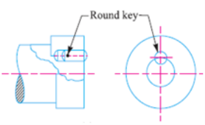
Splines
A range of keys made as a crucial a part of the shaft are known as splines. Keyways are supplied with inside the hub. These are used for excessive torque transmission e.g. In car transmission. Splines additionally allow the axial motion.
Design of Sunk Keys
Figure indicates the forces performing on a square key having width w and peak h. Let l be the duration of the important thing.
Torque is transmitted from the shaft to the hub thru key. Shaft applies a pressure P on the important thing and the important thing applies a same pressure at the hub.
Therefore the secret's acted upon with the aid of using same forces of value P, one implemented with the aid of using the shaft (at the decrease portion) and the opposite due to the response of hub (at the top portion).
As those forces aren't in equal plane, they represent a pair which attempts to tilt the important thing.
Therefore same and contrary forces P’ additionally act on the important thing, which offer a resisting couple that maintains the important thing in position.
As the precise place of pressure P isn't known, to simplify the evaluation it's far assumed that the pressure P acts tangential to the shaft. If T is the torque transmitted,

Where, d = diameter of the shaft
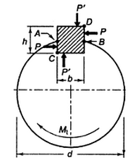
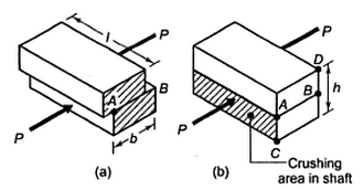
In the design of key two types of failures are considered, shear failure and crushing failure.
Area resisting shear failure = w l
Shear stress, τ = 
Crushing Area = l h/2
Crushing stress, σcrushing = 
Tables are available which give standard cross-sections for square and rectangular keys corresponding to different shaft diameters. But in the absence of such data, following relations are generally used:
For Rectangular Key: w = d / 4 and h = d / 6
For Square Key: w = h = d /4
For a known diameter of shaft, w and h can be calculated using these relations and then using the above strength equations required length of the key is calculated for given values of allowable stresses. Length is calculated both for shear and crushing and then maximum value out of the two is considered.
Classification of pins:
Exist an extensive type of trendy pins sorts and dimensions, in addition to unique designs to precise applications. Industrial pins may be categorized in an effort to his feature and bureaucracy into numerous categories, which includes: dowel pins, spring pins, cotter pins and twine clips, hitch and lynch pins or unique pins.
DOWEL PINS
Dowel pins are commercial fasteners which are used to sign up for or extra objects together. They are short, cylindrical rods that may be made of various substances which includes wood, steel and polymer. Exists numerous kinds of dowel pins how we will see below: -
Drive pins
Have an interference match and have to be hammered right into a mating hollow. They are not unusual place for rotary and transferring applications.
Groove pins
Are engraved with longitudinal or helical grooves. These grooves are intended for adhesives to alleviate hydraulic strain and enhance holding.
Knurled pins
Have a knurled floor to enhance the pin's grip. Most of this knurled floor are straight, helical and diamond knurls.
Pull dowel pins
Have a threaded hollow at one stop so a screw may be inserted. It is mainly used to help the eliminating of the pin from a blind hollow Tapered pins those pins have the shape of a truncated cone.
SPRING PINS:
Spring pins have a frame diameter which is bigger than the hollow diameter. The spring motion of the pin lets in it to compress because it assumes the diameter of the hollow.
A spring pin is taken into consideration are cost-effectives due to the fact the radial pressure exerted through the pin retains it with inside the hollow save you loosening created through vibration or surprise and requiring less training than different kinds of pins. There are kinds of spring pins:
Coiled spring pin
Additionally referred to as spiral pin, this sort of pin offers a great flexibility in diameters, uniform electricity and identical pressure distribution, additionally are shock-soaking up fastening elements.
Slotted spring pin
Additionally called roll pins, slotted spring pins are headless cylindrical pins rolled from a strip of fabric with a slot of the whole period to permit the pin to have a few flexibility at some point of insertion.
HITCH AND LYNCH PINS:
Hitch pins and their versions are easy sorts of hardware used to quickly mount or conjoin mating additives for excessive necessities functions than cotter pins.
Linch pins
Are designed to maintain a rotating tool on its axle, however it could additionally be used as a fastener as well. Both of those kinds of pins require predrilled holes in shafts and a few shape of a lock to be effective.
Hitch pins
Hyperlink mating additives and are held in function on one cease by the usage of cotter pin, and with inside the different cease a bend or cope with to save you removal. This sort of pin can attain an enormous load constantly that it won’t be carried out on the cotter pin.
Clevis pin
Is a hardware piece with a head, a cylindrical frame and a hollow that is routed thru a mating clevis fastener to bring together additives? This pins are designed to soak up lateral pressure and rotate to permit freedom of motion for supported objects.
A cotter pin is needed to save you the clevis pin from loosening.
Exist generic Clevis pins with numerous holes for regulate the pin to exceptional applications, as we will see at the proper picture.
Design of Pins:
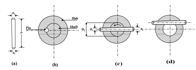
Round and taper pins are easy cylindrical pins without or with a taper and they provide powerful method of fastening pulleys, gears or levers to a shaft. It can be equipped such that 1/2 of the pin lies with inside the hub and the alternative 1/2 of with inside the shaft as proven in figure.
The pin can be pushed thru the hub and the shaft as in figure or as in figure these joints supply fantastic grip and the pins are subjected to a shear load. For example, for the shaft with inside the assembly proven in figure, the pin is beneath double shear and we have

Where d is the diameter of the pin at hub-shaft interface, τ is the yield strength in shear of the pin material and T is the torque transmitted.
Theories of failure:
Theories of failure describe the elastic failure of the mechanical additives. At the time of running gadget additives subjected to diverse masses which motive unique kinds of pressure in it.
Theories of failure assist us to decide the secure dimensions of the gadget additives whilst they're subjected to bi-axial or tri-axial kingdom of stresses. Anything is failed if the precipitated pressure exceeds the elastic restriction and everlasting deformation of the thing takes location.
In brittle failure the direct separation takes location with none sort of considerable elongation while in ductile failure we are able to see considerable inelastic elongation earlier than the failure
Both kinds of failure depend upon the form of cloth with the aid of using which gadget thing is made. All the mechanical additives failed whilst elastic restriction is reached to a positive fee and yielding starts. Different theories were proposed for unique substances and failures.
These theories are used to acquire the connection among stresses precipitated beneath bi-axial and tri-axial kingdom of pressure situations and the cloth residences that are received with the aid of using the anxiety check or compression check.
These residences are Sut (remaining energy in anxiety), Syt (yield energy in anxiety) and so on. The yielding within side the cloth relies upon the numerous pressure additives.
The failure of any mechanical element relies upon different factors like residences of cloth, form of loading and temperature etc. as an example an energy screw subjected to torsional second in addition to axial force, an overhang crank is subjected to blended bending and torsional second, equal with inside the case of bolts of the bracket that are subjected to forces that reasons tensile pressure and shear pressure, in which as crank shafts and connecting rods are examples of the ones additives that are subjected to complicated masses.
Before designing of any gadget element numerous experiments are executed on them to acquire secure running pressure beneath blended loading situations.
These experiments assist us to decide the unique residences of the substances beneath comparable loading situations.
But every so often it isn't feasible to carry out those exams for unique feasible mixtures of load to acquire mechanical residences. Generally maximum of the mechanical residences of anything are received with the aid of using anxiety check that's executed on UTM (Universal Testing Machine).
These residences are yield energy, remaining tensile energy and percent of elongation. Theories of failure supply a courting among the energy of gadget thing that are subjected to complicated kingdom of stresses with the mechanical residences that are received throughout the anxiety check.
Following are the important thing factors that are beneficial in higher information of theories of failure:
σ1, σ2 and σ3 are the precept stresses precipitated at a factor at the gadget element in 3 mutual perpendicular guidelines because of the unique loading situations. We use unique theories to acquire the connection among σ1, σ2 and σ3 with the cloth residences like Syt (yield shear energy in anxiety), Sot (remaining energy in anxiety), Sys (yield energy in shear) and element of protection FOS (N).
Under uniaxial kingdom of pressure situation i.e. most effective σ1 is appearing at the gadget thing then the energy criterion and all theories of failure will supply the equal end result so we don't have any requirement of idea of failure in case of uniaxial kingdom of pressure situation.
In case of bi-axial and tri-axial kingdom of pressure situations all of the theories of failure will offer unique results. So for the secure layout of anything beneath bi-axial and tri-axial kingdom of pressure situation suitable idea of failure ought to be selected.
Under bi-axial and tri-axial kingdom of pressure situations all of the theories of failure offer nearly equal end result whilst σ1 could be very massive compared to the σ2 and σ3.
1. MAXIMUM PRINCIPLE STRESS THEORY:
This idea changed into proposed with the aid of using W.J.M Rankin. This is one of the oldest and easy theories. According to this idea the failure within side the mechanical issue takes area while they're subjected to bi-axial or tri-axial kingdom of strain after which the cost of most precept strain reaches the yield electricity or final electricity of the fabric.
In this idea simplest most precept stresses are take into account, relaxation all of the precept stresses have now no longer any effects on it. If we take into account 3 precept stresses σ1, σ2 and σ3 at a factor on a device issue then σ1 > σ2 > σ3.
The situation of the failure is,
σ1 = Syt or σ1 = Sut
Maximum precept strain idea is taken into consideration because the first-class idea of failure for brittle substances, however it's also appropriate for ductile substances beneath the subsequent kingdom of strain conditions:- Uniaxial kingdom of strain situation simplest Bi-axial kingdom of strain situation while precept stresses are like in nature.
Here σ2 is not noted due to not like nature. Hydrostatic kingdom of strain situation i.e. while σ1 = σ2 = σ3.
GRAPHICAL REPRESENTATION:
A rectangular represents the kingdom of stresses beneath = this idea. Square is split into 4 quadrants i.e. in first quadrant each σ1 and σ2 are fantastic or tensile in nature. In 2nd quadrant σ1 is poor i.e. compressive in nature and σ2 is fantastic. In 1/3 quadrant each σ1 and σ2 are poor i.e. compressive in nature and in closing i.e. fourth quadrant σ1 is fantastic and σ2 is poor
2. MAXIMUM PRINCIPAL STRAIN THEORY:
This idea additionally called Saint Venant’s idea. According to this idea the ductile fabric begins off evolved yielding while the most precept stress reaches at that cost at which yielding happens in easy anxiety or we are able to say that the minimal precept stress cost is identical to the yield factor stress in easy compression.
This idea isn't appropriate for the ductile substances as it offers over secure dimensions of the ductile fabric. The layout equation consistent with this idea is,
σ1 – µ (σ2 and σ3) ≤ Syt
GRAPHICAL REPRESENTATION:
The form of the diagram consistent with the precept stresses is sort of a Rhombus that's symmetrically located with recognize to the axis. The signal of stresses is identical because the preceding idea however the form of diagram is changed.
3. MAXIMUM SHEAR STRESS THEORY:
This idea changed into proposed with the aid of using Coulombs and Guest.
According to this idea the failure of any mechanical issue happens while it's far subjected to bi-axial or tri-axial stresses after which the most shear strain at any factor of the issue reaches as much as the cost that's identical to the most shear strain within side the preferred specimen of the anxiety check while yielding is In the anxiety check the specimen is subjected to the uniaxial kingdom of strain i.e. σ2 = 0. So the most shear is identical to the 1/2 of the distinction among the most and minimal precept strain.
Therefore the most shear in easy anxiety is identical to the 1/2 of of the tensile strain. Design equation of most shear strain idea is,
Absolute T max = Syt or (σ1 – σ2)/2 = Syt
This idea isn't appropriate for ductile substances as it will provide over secure layout for ductile additives. This idea isn't relevant to substances subjected to hydrostatic kingdom of stresses, in this example shear strain is sort of 0 because of this that the failure with inside the fabric will now no longer happens that's impossible. Graphically a Hexagon represents the strain distribution which indicates that the substances will attain its elastic restriction while the stresses (σ1and σ2) cross outdoor the region.
4. TOTAL STRAIN ENERGY THEORY:
This idea changed into given with the aid of using Beltrami Haigh’s. According to this idea the engineering additives beneath the complicated stresses fails while the whole stress strength with inside the frame is identical to the stress strength at elastic limits in easy anxiety.
This idea states that after a cloth deformed completely because of the diverse stresses. The cost of those stresses boom regularly from 0 cost because of this we are able to say that the preliminary stress strength is unbiased of the character of stresses and is sort of constant.
The layout equation consistent with this idea is,
σ12 + σ22+ σ32 – 2µ (σ1σ2 + σ2σ3 + σ3σ1) = (Syt)2
This idea is relevant for the ones brittle substances who has elastic restriction strain in anxiety and compression are different. The graphical illustration of this idea is proven with the aid of using the Ellipses that are inscribed with the aid of using the parallelogram. The fabric mechanical issue reaches its elastic restriction while the stresses (σ1and σ2) fall outdoor the ellipse.
5. MAXIMUM SHEAR STRAIN ENERGY THEORY:
This idea is likewise called the most distortion strength idea. This idea changed into given with the aid of using M.T. Huber and R. Von Mises.
This idea states that the inelastic motion at any factor with inside the engineering issue begins off evolved because of diverse stresses while the stress strength of distortion in keeping with unit quantity is absorbed at a factor is identical to the stress strength of distortion absorbed in keeping with unit quantity at any factor in a bar that's confused to the elastic restriction beneath the uniaxial kingdom of strain with inside the easy anxiety or compression check.
So we are able to say that the part of the stress strength produce alternate with inside the form of the detail is meant to be absolutely answerable for the failure of the fabric with the aid of using yielding.
This idea is taken into consideration because the first-class and secure amongst all of the theories for designing any mechanical issue. The layout equation consistent with this idea is,
(σ1-σ2)2 + (σ2-σ3)2 + (σ3-σ1)2 = 2 (Syt)2
It typically has round cross-segment and may be stable or hollow. Shafts are supported at the bearings and transmit torque with the assist of gears, belts and pulleys etc. Shafts are typically subjected to bending second, torsion and axial pressure or a mixture of those three.
So the shafts are designed relying upon the mixture of masses its miles subjected to. Spindle stub and axle are a few vital forms of shaft. Small shaft is known as spindle. Shaft crucial a part of the top mover is known as stub shaft.
An axle is a non-rotating member that includes no torque and is used to help rotating wheels, pulleys etc. And consequently is subjected to bending second only.
Shaft Materials
- Hot-rolled simple carbon metallic is the least highly-priced fabric used for shafts.
- These basically require machining to do away with the scales of warm rolling process.
- Cold rolled simple carbon metallic gives higher yield power and persistence power however the bloodless running induces residual stresses.
- Surface is clean in this example and quantity of machining consequently is minimal. It is used for widespread motive transmission shafts.
- When a shaft is to paintings beneath intense loading and corrosive situations and require greater power, alloy steels are used, typically having Ni, Cr, Mo and V as alloying elements.
- Alloy steels are highly-priced.
- Sometimes shafts are warmth dealt with to enhance hardness and surprise resistance and floor hardening strategies also are used if excessive put on resistance is the requirement.
- As the shafts transmitting electricity are subjected to fatigue loading, consequently better issue of protection of three to four is used on the idea of yield power for static load analysis.
Design of Shafts
Shafts are designed on the idea of power or pressure or both.
Design primarily based totally on power is to make certain that pressure at any vicinity of the shaft does now no longer exceed the fabric yield pressure.
Design primarily based totally on pressure is to make certain that most deflection (due to bending) and most twist (because of torsion) of the shaft is in the allowable limits.
Rigidity attention is likewise very vital in a few instances for instance function of an equipment hooked up at the shaft will alternate if the shaft receives deflected and if this fee is greater than a few allowable limit, it is able to result in excessive dynamic masses and noise with inside the gears.
In designing shafts on the idea of power, the subsequent instances can be considered:
(a) Shafts subjected to torque
(b) Shafts subjected to bending second
(c) Shafts subjected to mixture of torque and bending second
(d) Shafts subjected to axial masses further to mixture of torque and bending second
Shafts Subjected to Torque
Maximum shear stress developed in a shaft subjected to torque is given by,

Where T = Twisting moment (or torque) acting upon the shaft,
J = Polar moment of inertia of the shaft about the axis of rotation
=  for solid shafts with diameter d
=  for hollow shafts with do and di as outer and inner diameter.
r = Distance from neutral axis to the outer most fibre = d/2 (or do/2)
So dimensions of the shaft subjected to torque can be determined from above relation for a known value of allowable shear stress, [τ].
Shafts Subjected to Bending Moment
Maximum bending stress developed in a shaft is given by,

Where M = Bending Moment acting upon the shaft,
I = Moment of inertia of cross-sectional area of the shaft about the axis of rotation
=  for solid shafts with diameter d
=  for hollow shafts with do and di as outer and inner diameter.
y= Distance from neutral axis to the outer most fibre = d / 2 (or do/2)
So dimensions of the shaft subjected to bending moment can be determined from above relation for a known value of allowable tensile stress.
Shafts Subjected to Combination of Torque and Bending Moment
When the shaft is subjected to combination of torque and bending moment, principal stresses are calculated and then different theories of failure are used. Bending stress and torsional shear stress can be calculated using the above relations.


Maximum Shear Stress Theory
Maximum shear stress is given by,

 is called equivalent torque, Te, such that

Maximum Principal Stress Theory
Maximum principal stress is given by,

 is called equivalent bending moment, Me, such that
σ = 
A.S.M.E. Code for Shaft Design
According to A.S.M.E. Code, the bending and twisting moment are to be multiplied by factors kb and kt respectively, to account for shock and fatigue in operating condition.
Therefore, if the shaft is subjected to dynamic loading, equivalent torque and equivalent bending moment will become:
 And
And 
Table Values of kb and kt for different types of loading
| kb | kt | |
Gradually applied load | 1.5 | 1.0 | |
Suddenly applied load (minor shock) | 1.5-2.0 | 1.0-1.5 | |
Suddenly applied load | 2.0-3.0 | 1
.5-3.0 |
Design of Shaft on the basis of Rigidity
Torsional Rigidity
For a shaft subjected twisting moment, the angle of twist is given by,
θ = 
Where, T = Torque applied
L = Length of the shaft
J = Polar moment of inertia of the shaft about the axis of rotation
G = Modulus of rigidity of the shaft material
Therefore for the known values of T, L and G and allowable value of angle of twist, diameter of the shaft can be calculated.
Lateral Rigidity
Bending moment acting on any shaft is given by,

Integrating this equation twice with respect to x and applying the boundary conditions, y can be calculated. y should be ≤ allowable value of deflection, [y].
A.S.M.E. Code for Shaft Design
According to A.S.M.E. Code, the bending and twisting moment are to be multiplied by factors kb and kt respectively, to account for shock and fatigue in operating condition. Therefore, if the shaft is subjected to dynamic loading, equivalent torque and equivalent bending moment will become:
 And
And 
Table: Values of kb and kt for different types of loading
| kb | kt |
Gradually applied load | 1.5 | 1.0 |
Suddenly applied load (minor shock) | 1.5-2.0 | 1.0-1.5 |
Suddenly applied load | 2.0-3.0 | 1.5-3.0 |
- A shaft coupling is one of the maximum not unusual place device factors due to the fact it's miles simply so critical in energy transmission systems. Thus, they locate use in plenty of programs and carrier environments.
- As an end result, designers and engineers have designed many versions of couplings for unique carrier situations and environments over the years.
- This article will familiarize you with the specific sorts of couplings and talk selecting the proper alternative on your application. A coupling is a mechanical tool that connects comparable or diverse shafts in machines to transmit energy and motion.
- It is often a brief connection (however may be everlasting in a few instances) and able to elimination for carrier or replacement. A coupling can be inflexible or bendy.
- Due to the supply of many designs, there may be stark variations with inside the production and feature of sorts of mechanical couplings. Some couplings can hook up with shafts without transferring the shaft, at the same time as maximum would require shaft motion for fitting.
- In maximum instances, a coupling does now no longer alternate the path of movement or angular velocity, in contrast to gears. It can't be related or disconnected mid-operation, in contrast to clutches.
- Couplings can best switch torque over quick distances, for longer distances chain drives and belt drives are higher alternatives.
- Couplings are regularly paired with lead screw assemblies to attach the screw shaft in-line to a motor. The coupling works through keeping a sturdy however bendy connection always among shafts to switch movement from one shaft to another.
- It does so in any respect values of hundreds and misalignment without allowing any relative movement among the 2 shafts.
The Purpose of Couplings
A shaft coupling can carry out more than one capabilities in a device.
The layout can also additionally contain greater than this sort of coupling capabilities into the product’s feature in superior programs.
Let us take a short examine what those are:
- Power transmission Shock and vibration absorption
- Misalignment accommodation
- Heat waft interruption
- Overload protection
- Power transmission
The number one reason in maximum instances is energy and torque transmission from a riding shaft to a pushed shaft — for example, a coupling connecting a motor to a pump or a compressor.
Absorb surprise and vibration a shaft coupling can easy out any shocks or vibrations from the riding detail to the pushed detail.
Interrupt warmness waft a shaft coupling also can interrupt the waft of warmth among the related shafts. If the top mover has a tendency to warmness up all through operation, the equipment at the force facet is included from being uncovered to this warmness.
Overload protection
Special couplings referred to as
Overload Safety
Mechanical Coupling are designed with the aim of overload protection.
On sensing an overload condition, those torque proscribing couplings sever the relationship among the 2 shafts. They both slip or disconnect to shield touchy machines.
Types of Couplings
Couplings are available a bunch of various shapes and sizes. Some of them paintings extraordinary for frequent programs, at the same time as a few others are custom-designed for absolutely unique scenarios.
To make a knowledgeable choice, it's miles critical to be aware about the competencies and variations of the specific sorts of couplings.
This phase gives statistics approximately the subsequent sorts of couplings and the way they paintings:
Rigid coupling
As the call suggests, an inflexible coupling allows little to no relative motion among the shafts.
Engineers decide upon inflexible couplings whilst specific alignment is necessary. Any shaft coupling that may limitation any undesired shaft motion is referred to as an inflexible coupling, and thus, its miles an umbrella time period that consists of specific unique couplings.
Some examples of this form of shaft coupling are sleeve, compression and flange coupling.
Once an inflexible coupling is used to attach gadget shafts, they act as an unmarried shaft. Rigid couplings locate use in vertical programs, inclusive of a vertical pump.
They also are used to transmit torque in excessive torque programs inclusive of big mills. They can't appoint bendy couplings, and hence, increasingly mills now use inflexible couplings among turbine cylinders.
This association guarantees that the turbine shaft acts as a non-stop rotor.
Flexible coupling
Any shaft coupling that may allow a few diploma of relative movement among the constituent shafts and offer vibration isolation is referred to as a bendy coupling. If shafts had been aligned all of the time flawlessly and the machines did now no longer circulate or vibrate all through operation, there could be no want for a bendy coupling.
Unfortunately, this isn't always how machines perform in reality, and architects need to address all of the above troubles in device layout. A bendy coupling can restoration them to a sure extent.
It can lessen the quantity of wear and tear and tear at the machines through the issues and dynamics which can be part of nearly each system. “Flexible coupling” is likewise an umbrella time period and homes many unique couplings beneath its call.
These couplings shape the bulk of the sorts of couplings in use today. Some famous examples of bendy couplings are tools coupling, general joint and Oldham coupling.
Mechanical spring is an elastic member whose number one characteristic is to deflect beneath load and to get better its authentic form and role whilst load is released. Springs are used to soak up shocks and vibrations (e.g. Automobile suspension system), save energy (e.g. Springs n clocks and toys), degree pressure (e.g. Spring balance) and to use pressure and manipulate motion (e.g. Cam and follower).
Helical springs
The helical springs are crafted from a cord coiled with inside the shape of a helix as proven in Figure 1. Cross-phase of the cord is normally round and it may be rectangular or square also. Helical springs are clean to manufacture, dependable and feature a consistent spring fee i.e. spring deflection is at once proportional to the pressure acting. These are of types – compression helical springs and anxiety helical springs.
Compression helical springs are designed to take compressive masses and that they get compressed beneath the loading and the anxiety helical springs are designed to take tensile masses and that they get elongated beneath the outside masses. The load acts alongside the axes of those springs. In helical sprigs, the cord is subjected to torsional shear stress. Helical springs also are categorized as closely-coiled and open-coiled springs.
In closely-coiled springs, cord is coiled so near that the aircraft containing every flip is sort of at proper angles to the axis of the helix i.e. the helix attitude may be very small, generally much less than 10°. In open-coiled helical springs, the cord is so coiled that there's an opening among the 2 consecutive turns i.e. the helix attitude is large.
Types of Helical Spring:
Helical springs are available in 4 simple categories:
- Compression
- Extension
- Torsion
- Spring publications
They are versatile, in that they're used in lots of distinct forms of applications. You may discover helical springs utilized by the clinical industry, automotive, and creation industries.
Before you could start the layout of the additives you need, you'll should decide which of the types is maximum appropriate:
Compression Springs
These springs have an open coil machine this is designed to oppose compression alongside the axis of the wind. In different words, loosely wound coils face up to the pressure of compression, the quantity of pressure resisted may be tormented by adjusting the tightness of the wind.
This is the maximum not unusual place form of configuration and they're normally utilized in mixture with a rod or are geared up inner a cylindrical hole.
Extension Springs This form of coil is designed to soak up strength or save strength. In general, they may be used to create resistance to tensile forces. The diploma of hysteria is decided via way of means of how tightly wound the coils are. These coils can be utilized in business robots, as door locks, or in perambulators.
Torsion Springs
These coils are characterized via way of means of their twisting electricity. The bendy wind of the item shops mechanical strength. As the coil is twisted greater tightly, the pressure, or torque, will become more potent with inside the contrary direction.
Torsion helical springs are used to perform clothespins, storage doors, and suspension structures on automobiles.
Naturally, those structures are to be had in lots of distinct sizes from very tiny to very huge and effective.
Spring Guides
These publications are acknowledged via way of means of some of distinct names, together with coil pipes, clinical springs, and cable sheaths. They are lengthy and slim and are used to offer bendy assist inside a project. They can be located in bicycle brakes, manipulate cables on animatronics, or is probably used as reinforcement inner of plastic tubing.
The use of helical springs is not unusual place, however have to now no longer be under-valued. This effective and bendy device handles a exquisite deal of pressure in lots of distinct guidelines and with lots of results.
Terminology of Helical Springs
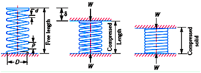
Solid Length: Length of the spring when it is compressed so that the coils touch each other.
Solid Length, Ls = n.d
Where n = numbers of coils and d = wire diameter
Compressed Length: Length of the spring, when it is subjected to maximum compressive force.
Even under the worst load, minimum clearance is maintained between the two adjacent coils so that they don’t clash with each other. It is called clash allowance and is generally taken as 15% of the maximum deflection.
Free Length: Length of the spring in the free or unloaded condition.
Free Length = Solid length + Maximum compression + clash allowance
= nd + δmax + 0.15 δmax
Spring Index: Ratio of the mean diameter of the coil to the diameter of the wire .
Spring index, C = D/d
Spring Rate/Spring Stiffness/Spring Constant: Force required to produce unit deflection in the spring.
Spring Rate, k = W / σ where, and
Pitch of the Coil: Axial distance between adjacent coils of the spring in uncompressed state.
Pitch of the Coil = p = Free Length / (n - 1)
Design of Helical Springs
Stress in Helical Springs
Under the compressive load, W acting on the spring, coil of the spring is subjected to two types of stresses – direct shear stress and torsional shear stress due to twisting of the coil.
Torque = T = W . D / 2


In the analysis above effect of stress concentration is not considered. AM Wahl introduced a factor called Wahl’s Stress Factor, K that takes care of stress concentration also along with the shear stress.
According to Wahl, Maximum shear stress is given by,
Maximum shear stress = 
Wahl’s Factor is given by,
Wahl’s Factor, K = 
Bulking of springs:
A spring which deforms in a non-axial route below compression is stated to have buckled. Buckling may be attributed to a spring’s greater giant loose period and cease situations being incorrect to distribute the weight all alongside the coil’s circumference evenly.
Also, compression spring buckling or bending takes location at some stage in deflection (for a given loose period which will become too large) due to the spring’s instability due to excessive slenderness ratio.
During compression, the instability reasons the coils to tremble and shift in a non-axial route. The load at the spring also can create stress with inside the shifted coils, which can become plastering the coils to the factor of unfavorable them. When the spring is damaged, it cannot go back to its unique kingdom nor offer the supposed pressure it become supposed to guide.
SPRING SLENDERNESS RATIO
A spring’s slenderness ratio is used to check if a spring has the capacity to buckle or bend. Thus, the slenderness ratio of the spring is the percentage of the imply diameter to its period. For instance, a spring’s imply diameter that is over 3 instances its period will supply manner and buckle. It is, however, feasible to have an outer diameter this is 3 instances much less than the spring’s loose period which gives numerous says to cut back buckling in springs.
1. CUSTOM SPRINGS:
Custom springs are the ones whose specification (diameter, period, rate, etc.) had been strictly maintained primarily based totally on what the consumer needs and the utility the spring be used.
These spring kinds also can have unique functions primarily based totally at the customer’s orders in a bid to decorate the spring’s residences and additionally offer compatibility with the mating parts. To save you a spring buckling, you want to make sure that once developing a custom spring, one of a kind modifications are made to its layout to provide it a right dimension.
There can also be a want to extrude the spring’s slenderness ratio, and the extrude may be accomplished via way of means of: Adding coils to the spring reducing the spring’s loose period Increasing custom spring’s outer diameter
2. STOCK SPRINGS:
An inventory spring is one which has already been designed via way of means of the producer. As such, its layout has now no longer been decided explicitly via way of means of you. These springs are stored with inside the organization’s stock and feature already been designed?
It is really well worth noting that regardless of having no manipulate over the spring’s layout, you could nevertheless save you its buckling or bending that is usually due to the spring’s longer loose period. Buckling may be averted via way of means of adjusting the location of the inventory spring.
All it’ll take is to: Add a rod with inside the middle of the spring. Place the spring in a tube to keep away from buckling
These hints will maintain your spring in location and save you it from coming off at some stage in installation. Nonetheless, minimum friction may nevertheless be obvious with the shaft’s wall or hollow despite the fact that it’ll be less difficult to handle.
3. USE A SPRING LENGTH HIGHER THAN LK:
It is crucial to expound that the use of a spring with its period better than the essential buckling period (LK), can save you buckling. LK is a characteristic of the spring’s geometry and the sort of cease fixations at the spring. That being the case, LK is impartial of the most appropriate pressure with inside the spring’s body, theoretically.
4. RELY ON A REPUTABLE MANUFACTURER:
Springs that won’t buckle also can depend upon the knowledge of the organization or producer designing it. That is why, in maximum cases, it's far really useful to pick out custom springs.
Their layout will in particular be tailor-made to the system or utility they may be used. Such springs have an intensive layout and maximum likely, won’t buckle below particular loads. Stock springs, on the alternative hand, will should be decided on primarily based totally at the system it's far maximum appropriate to be used.
End condition of springs:
When it involves spring ends, you've got quite a few alternatives. In a few cases, each ends will fit, however it's also feasible to have extraordinary give up kinds at the equal spring. Your desire will rely on the process your spring is needed to do. In deciding on the proper give up kind or kinds on your springs it's far beneficial to recognize every give up kind and the way they function.
Compression Spring End Types
The common compression spring give up kind alternatives encompass open or closed. The maximum typically used kind is a closed or squared off give up kind. In the case of closed ended springs, the distance among the final coils is minimized in order that the coils touch, and it sits flat.
Open ended springs, however, aren't squared off and generally tend to want a few shape of support, inclusive of a rod.
Closed ends are extra not unusual place, while open ends are used for unique packages or for longer cut-to-duration inventory springs.
As a secondary process, each closed and open ends may be floor down. Grinding the ends of compression springs create a flat floor to lessen buckling and boom stability.
Typically, compression springs with large twine diameters and closed ends are floor down, whilst smaller twine diameters and open-ended compression springs best want grinding in unique packages.
Keep in mind, grinding is a secondary operation, which will increase the cost.
Extension Spring End Types
Hooks and loops are the number one give up kind alternatives for extension springs. Loops are completely closed all of the manner around, while hooks have an opening among the frame of the spring and the give up of the hook.
Stock extension springs are commonly made with loop ends, however with an easy cut, a hook may be made. Hooks and loops are to be had in some extraordinary fashion alternatives to fit utility needs.
The maximum broadly used give up patterns for extension springs are crossover, machine, side, and double loop ends. W.B. Jones additionally has the functionality to fabricate prolonged or specialized ends to satisfy particular requirements. Please touch our layout group for in addition assistance.
Torsion Spring End Types
In the case of torsion springs, the maximum not unusual place and flexible give up kind is an undeniable immediately leg, without a bends. Customized designs are to be had for packages that require a torsion spring with bends.
A sample, print, photo, or comic strip is all that an excellent spring producer would require to decide the torsion spring layout this is needed.
Design of leaf springs: nipping:
There are sorts of leaf spring used for vehicles; the multi leaf and the parabolic leaf spring. The multi leaf spring layout is primarily based totally on using a flat trapezoid geometry, with reduce leaves stacked one on pinnacle of the other.
This ends in a multi leaf layout with specific lengths of every leaf. When a multi leaf spring deflects the leaves circulate relative every other.
The touch among the leaves produces a friction among them, which ends up in a distinction in load among compression and decompression. The longest leaf has eyes for assembling to the car body.
The energy of this leaf and the eyes are important and occasionally the second one leaf could have protection loops which hook round the principle eye as an again up in case of failure.
The center of the spring is typically constant to the car axle with U-bolts.
The parabolic spring is designed for low inner friction and lowest viable weight and therefore has fewer leaves.
The leaves are partially given a parabolic form from the center to the quilt of the leaf, which offers a same bending pressure degree alongside the parabolic part. This guarantees green use of fabric and minimal weight.
The form of the leaves are such that touch among the leaves handiest exists on the center and the ends. And for the reason that center of the leaf spring is constant to the axle with U-bolts, the handiest friction comes from the quit contacts.
Rubber pads also are occasionally used to decrease the friction. As with multi-leaf springs, the energy of the eyes is an important protection factor.
Originally Leaf spring called laminated or carriage spring, a leaf spring is an easy shape of spring, usually used for the suspension in wheeled vehicles.
It is likewise one in every of the oldest styles of springing, courting again to medieval times.
Sometimes known as a semi-elliptical spring or cart spring, it takes the shape of a slim arc-shaped period of spring metallic of square cross-section.
The middle of the arc presents location for the axle, while tie holes are supplied at both end for attaching to the automobile body.
For very heavy vehicles, a leaf spring may be crafted from numerous leaves stacked on pinnacle of every different in numerous layers, frequently with gradually shorter leaves.
Leaf springs can serve finding and to a degree damping in addition to springing functions. A leaf spring can both be connected without delay to the body at each ends and connected without delay at one end, usually the front, with the alternative end connected through a shackle, a short swinging arm.
The shackle takes up the tendency of the leaf spring to lengthen whilst compressed and accordingly makes for softer springiness.
Materials for leaf spring:
The fabric used for leaf springs is mostly a simple carbon metallic having 0.90 to 1.0% carbon. The leaves are warmness treated after the forming process. The warmness treatment of spring metallic produces greater strength and therefore greater load capacity, greater range of deflection and higher fatigue properties. According to Indian standards, the endorsed substances are:
1. For automobiles: 50 Cr 1, 50 Cr 1 V 23, and fifty five Si 2 Mn ninety all used in hardened and tempered state.
2. For rail road springs: C fifty five (water-hardened), C 75 (oil-hardened), 40 Si 2 Mn ninety (water hardened) and fifty five Si 2 Mn ninety (oil-hardened).
3. The physical properties of some of those substances are given in the following table. All values are for oil quenched circumstance and for unmarried warmness only
Leaf springs (also known as flat springs) are made out of flat plates. The gain of leaf spring over helical spring is that the ends of the spring can be guided alongside a definite path as it deflects to act as a structural member in addition to energy soaking up Thus the leaf springs can also additionally carry lateral loads, brake torque, driving torque etc., further to shocks.
Consider a single plate fixed at one end and loaded at the other end as shown in Fig
This plate may be used as a flat spring.
Let t = Thickness of plate,
b = Width of plate, and
L = Length of plate or distance of the load W from the cantilever end.
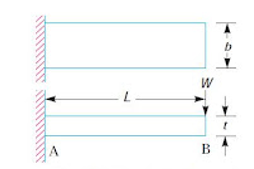
Fig. Flat spring (cantilever type)
We know the maximum bending moment at the cantilever end A.
M = W . L
And section modulus,
z = 
Bending stress in such a spring
σ = M/Z = 
We know that the maximum deflection for a cantilever with concentrated load at the free end is given by
δ = 
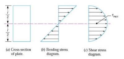
Consider a unmarried plate constant at one stop and loaded at the alternative stop as proven in Fig This plate can be used as a flat spring. It can be stated that because of bending second, pinnacle fibres can be in anxiety and the bottom fibres are in compression, but the shear strain is 0 at the extreme fibres and maximum at the centre, as proven in Fig. Hence for analysis, both stresses need not to be taken under consideration simultaneously. We shall recollect the bending strain only.
If the spring isn't of cantilever kind but it is like a simply supported beam, with duration 2L and cargo 2W with inside the center, as proven in Fig., then Maximum bending second with inside the Centre, as proven in fig, then Maximum bending second with inside the center,
M=W.L
Section modulus,
Z = b . t2
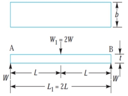
Fig. Flat spring (simply supported beam type)
The above relations give the stress and deflection of a leaf spring of uniform cross-section. The stress at such a spring is maximum at the support.
If a triangular plate is used as shown in Fig, the stress will be uniform throughout. If this triangular plate is cut into strips of uniform width and placed one below the other, as shown in Fig to form a graduated or laminated leaf spring, then

And …………………….(V)

………………………(V I)
Where n = number of graduated leaves,
A little attention will display that via way of means of the above arrangement, the spring will become compact in order that the gap occupied via way of means of the spring is notably reduced. When bending strain alone is considered, the graduated leaves can also additionally have 0 width on the loaded stop. But enough metallic should be furnished to aid the shear. Therefore, it will become necessary to have one or more leaves of uniform move-section extending clean to the stop. We see from equations (iv) and (vi) that for the identical deflection, the strain in the uniform move-section leaves (i.e. full duration leaves) is 50% greater than with inside the graduated leaves, assuming that every spring detail deflects in step with its very own elastic curve. If the suffixes F and G are used to indicate the full duration (or uniform move section) and graduated leaves, then


Or


…………………….( VII)
Adding 1 to both sides we have


……………………….(VIII)
Where W = total load on the spring = 
WG = load taken up by graduated leaves, and
WF = load taken up by full length leaves
From the equation (VIII), we may write

Or


Therefore bending stress for full leaves,


The definition in full length and graduated leaves is given by equation (VI) i.e
δ = 
Length of Leaf Spring Leaves
The length of the leaf spring leaves may be obtained as discussed below:
Let 2L1 = Length of span or overall length of the spring,
= Width of band or distance between centres of U-bolts. It is the ineffective length of the spring,
NF = Number of full length leaves,
NG = Number of graduated leaves, and
n = Total number of leaves = nF + nG.
We have already discussed that the effective length of the spring,
(When band is used)
= 2L1 – 2/3 l ………………………..(When U-bolts are used)
It may be noted that when there is only one full length leaf (i.e. master leaf only), then the number of leaves to be cut will be n and when there are two full length leaves (including one master leaf), then the number of leaves to be cut will be (n – 1), If a leaf spring has two full length leaves, then the length of leaves is obtained as follows:
Length of smallest leaf = 
Length of next leaf = 
Similarly,
Length of (n – 1) leaf = 
The nth leaf will be the master leaf and it is of full length. Since the master leaf has eyes on both sides, therefore.
Length of master leaf = 2 L1 + x (d + 1) × 2
Where d = Inside diameter of eye, and
t = Thickness of master leaf
The approximate relation between the radius of curvature (R) and the camber (y) of the spring is given by
The exact relation is given by
y(2R + y) = (L1)2
Where L1 = Half span of the spring.
Note: The maximum deflection (δ) of the spring is equal to camber (y) of the spring.
Nipping:
The stresses in more full-period leaves are 50% greater than the stresses in graduated-period leaves.
One of the techniques of equalizing the stresses in specific leaves is to pre-pressure the spring.
The pre-stressing is performed through bending the leaves to specific radii of curvature, earlier than they're assembled with the center clip.
As proven in Fig, the full-period leaf is given a extra radius of curvature than the adjoining leaf.
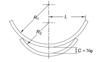
The radius of curvature decreases with shorter leaves.
The preliminary whole C among the more full-period leaf and the graduated-period leaf earlier than the assembly, is referred to as a ‘nip’.
Such pre-stressing, performed through a distinction in radii of curvature, is understood as ‘nipping’.
Key Takeaways:
- An inventory spring is one which has already been designed via way of means of the producer.
- That being the case, LK is impartial of the most appropriate pressure with inside the spring’s body, theoretically.
- The maximum typically used kind is a closed or squared off give up kind. In the case of closed ended springs, the distance among the final coils is minimized in order that the coils touch, and it sits flat.
References:
1. Design of Machine Elements, V.B. Bhandari, Tata McGraw Hill
2. Mechanical Engineering Design, J.E.Shigley, C.R.Mischke, R.G.Budynas and K.J. Nisbett, TMH
3. Machine Design, Pandya and Shah, Charotar Book Stall
4. Fundamentals of Machine Component Design by R.C.Juvinall and K.M. Marshek, John Wiley & Sons.
5. Machine Drawing by N. Sidheswar, McGraw-Hill
Unit - 3
Design of Keys, Shaft and Couplings