Unit - 1
Geometry of cutting tools in ASA and ORS
1.1.1 Tool signature in ASA system
Machine longitudinal plane, Machine transverse plane, and Reference plane are three mutually perpendicular planes used by the American Standards Association (ASA) for reference purposes. Two rake angles, two clearance angles, two cutting edge angles, and the nose radius of a single point cutting tool make up the ASA tool signature. The sequence of writing tool signatures in the ASA system is shown here, along with the names of various angles. It is important to remember that though various people may use various symbols, the sequence must be followed. Below is an example of a typical scenario.
ASA system of turning tool designation | ||||||
 |  |  |  |  |  |  |
 | 5  |  | 6  | 10  | 30  | 1/12 |
Back rack angle | 0  | |||||
Orthogonal rake angle (  | 5  | |||||
Back clearance angle |  | |||||
Side clearance angle | 6  | |||||
End cutting edge angle | 10  | |||||
Approach angle | 30  | |||||
Nose radius | 1/12 inch | |||||
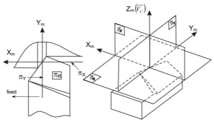
The ASA system's reference planes and axes
The following are the reference planes and coordinates used in the ASA system for tool geometry:
 and
and 
Where,
ΠR = Reference plane; plane perpendicular to the velocity vector (shown in Fig.)
ΠX = Machine longitudinal plane; plane taken in the direction of anticipated longitudinal feed and perpendicular to _R.
ΠY = [This plane is taken in the direction of presumed cross feed] Machine Transverse plane; plane perpendicular to both _R and _X
The longitudinal feed, cross feed, and cutting velocity (vector) axes are Xm, Ym, and Zm, respectively. Fig shows the key geometrical features and angles of single point tools in ASA systems, as well as their definitions.
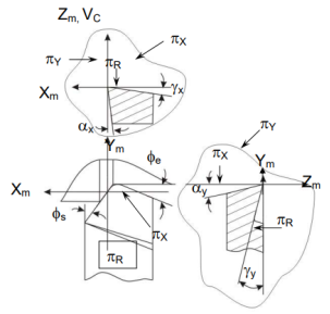
Tool angles in ASA system
• Rake angles in the ASA system:
 = side (axial rake: angle of inclination of the rake surface from the reference plane (
 ) and measured on Machine Ref. Plane,
  .
.
 = back rake: angle of inclination of the rake surface from the reference plane and measured on Machine Transverse plane,
  .
.
• Angles of clearance:
 = side clearance: angle of inclination of the principal flank from the machined surface (or
  ) and measured on
  plane.
 = back clearance: same as
  but measured on
  plane.
• Angles of cutting:
 = approach angle: angle between the principal cutting edge (its projection on
  ) and
) and  and measured on
 = end cutting edge angle: angle between the end cutting edge (its projection on
  ) from
  and measured on
r (radius of the nose) (in inch)
r = nose radius: curvature of the tool tip. It provides strengthening of the tool nose and better surface finish.
1.1.2 Tool signature in ORS system
For reference, the Orthogonal Rake System (ORS) uses three mutually perpendicular planes: Cutting plane, Orthogonal plane, and Reference plane. Tool signature in the ORS system consists of two rake angles, two clearance angles, two cutting edge angles, and the nose radius of a single point cutting tool, similar to the ASA system. Note that the ASA method measures nose radius in inches, but the ORS method measures it in millimetres. The sequence of writing tool signatures in the ORS system is shown here, along with the names of various angles. The sequence, as is customary, cannot be changed, however alternate notation can be used. Below is an example of a typical scenario.
OSR system of turning tool designation | ||||||
|  |  |  |  |  |  |
 | -7  | 10  | 8  | 15  | 60  | 0.8  |
Inclination angle () | 0  | |||||
Orthogonal rake angle (  | -7  | |||||
Orthogonal clearance angle (  | 10  | |||||
Auxiliary Orthogonal clearance angle  | 8  | |||||
Auxiliary cutting edge angle  | 15  | |||||
Principal cutting edge angle (  | 60  | |||||
Nose radius (r) | 0.8mm | |||||
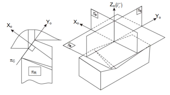
ORS planes and axes of reference
Where,
 = Perpendicular to the cutting velocity vector is a reference plane.,
 = plane perpendicular to the cutting plane
  as well as along the main cutting edge
 = Orthogonal plane is a plane that is perpendicular to both sides.
  and
and  and the axes;
XO = parallel to the intersection of  and
and 
Yo = parallel to the intersection of  and
and 
Zo = normal to both sides of the velocity vector Xo and Yo axes.
Fig. Shows the key geometrical angles used to depict tool geometry in the Orthogonal Rake System (ORS) and their definitions.
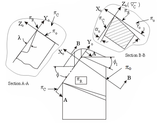
Tool angles in ORS system
• ORS rake angles
 = Angle of inclination of the rake surface from the Reference plane, orthogonal rake
  and is calculated in the orthogonal plane,
λ = angle of inclination; the distance between two points  from the expected longitudinal feed direction [
 ] and measured on
• Angles of clearance
 = angle of inclination of the major flank from orthogonal clearance of the principal flank: angle of inclination of the principal flank from orthogonal clearance of the principal flank from orthogonal clearance of the principal
  and measured on
 = angle of inclination of the auxiliary flank from the auxiliary cutting plane, auxiliary orthogonal clearance
  _o'as shown in Fig, and measured on auxiliary orthogonal plane.
• Angles of cutting
 = Angle between the main cutting edge and the main cutting edge
  as well as the predicted longitudinal feed or
  and measured on
 = auxiliary cutting angle: the angle formed by the intersection of two lines. πc’ and πx and measured on πr
r (radius of the nose) (mm)
r = radius of curvature of tool tip
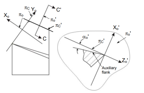
Auxiliary orthogonal clearance angle
Questions:
Select the correct answer from the given four options:
1. A turning tool's back rake is measured in the machine longitudinal plane.
(b) transverse plane of the machine
a) orthogonal plane;
b) orthogonal plane;
c) orthogon
(d) plane normal
2. When a turning tool's normal rake and orthogonal rake are the same,
(a) φ = 0
(b) φ1 = 0
(c) λ = 0
(d) φ1 = 90o
3. A turning tool's normal plane is always perpendicular to its axis.
(a) πR plane
(b) πY plane
(c) πC plane
(d) None of them
4. Any turning tool's principal cutting edge angle is measured on its face.
(a) πR
(b) πY
(c) πX
(d) πO
5. It is impossible for a cutting instrument to lose its sharpness.
(a) rake angle – positive
(b) rake angle – negative
(c) clearance angle – positive
(d) clearance angle – negative
6. A turning tool's orthogonal clearance and side clearance will be the same if its perpendicular cutting edge angle is
(a) φ = 30O
(b) φ = 45O
(c) φ = 60O
(d) φ = 90O
7. A turning tool's inclination angle is measured on its axis.
(a) reference plane
(b) cutting plane
(c) orthogonal plane
(d) normal plane
8. If a turning tool's normal rake and side rake are the same,
(a) φ = 00 and λ = 00
(b) φ = 900 and λ = 00
(c) φ = 900 and λ = 900
(d) φ = 00 and λ = 900
Answer of the objective questions
1 – (b)
2 – (c)
3 – (c)
4 – (a)
5 – (d)
6 – (d)
7 – (b)
8 – (b)
Key takeaway:
• Tool signature in the ORS system consists of two rake angles, two clearance angles, two cutting edge angles, and the nose radius of a single point cutting tool, similar to the ASA system. Note that the ASA method measures nose radius in inches, but the ORS method measures it in millimetres.
• Cutting tool geometry is a term that refers to the angles that the cutting edges have. To designate a cutting tool, certain attributes of the instrument are expressed in a specified and standardised manner.
1.2.1 Introduction:
Hard turning is done with a variety of tool materials, generally CBN, on hardened steels in the 45 to 68 Rockwell hardness range. Despite the fact that grinding is known for producing good surface quality at relatively modest feed rates, hard turning can achieve the same or superior surface finish at far greater material removal rates without the use of coolant or special tools (Fig). Although the method involves tiny cut depths and feed rates, estimates of reduced machining time for conventional hard turning compared to grinding are as high as 60% [1]. Rather than many grinding setups, a single setup may be sufficient for many hard turning operations. This also helps to the excellent accuracy that hard turning achieves. The cutting parameters chosen have a significant impact on the cutting forces and surface produced on the workpiece. Cutting forces on the tool and surface roughness created during workpiece finish hard turning can be utilised to assess process performance within a given range of cutting parameters.
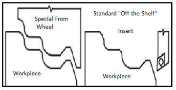
Fig: Grinding versus hard turning
Nomenclature
 Cutting speed in (m/min)
f Feed(mm/rev)
d Depth of cut (mm)
Fx Axial force(N)
Fz Cutting force(N)
Ra Surface roughness(microns)
Many researchers studied the cutting forces and surface finish created during severe turning. In finish hard turning, where the depth of cut is less than the tool's nose radius, the radial component of tool force is found to be the most significant . This distinguishes the operation from traditional turning, in which the radial force is just 0.3–0.5 times the cutting force. As a result, while defining the static and dynamic behaviour of such machining systems, the radial force cannot be overlooked. However, it has been shown that while hard turning with a variable hone edge radius tool, the tangential force is at its peak, boosting cut efficiency.
Due to low temperature and built up edge (BUE) development, many researches found increased cutting forces during forceful turning at low cutting speeds. The forces decreased as the cutting speed increased, which could be attributable to thermal softening of the work piece material caused by high cutting temperatures. The feed rate had a significant effect on cutting force, but it had no effect on thrust force, according to an ANOVA [10]. Another study found that when the feed, depth of cut, and nose radius increased, so did the cutting forces. Others found similar results, indicating that the depth of cut has an effect on machining forces. Researchers investigated the effect of cutting parameters on cutting forces and surface roughness during hard turning of MDN 250 steels using a coated ceramic tool at speeds up to 144 m/min. Cutting speed had no effect on forces, however depth of cut had an effect on feed force. Furthermore, feed rate and depth of cut both had a considerable impact on thrust and cutting forces.
The radial force component, rather than the tangential force, was found to be dominant during finish hard turning employing typical tool geometry. Because the cutting conditions in hard turning differ from those in typical material turning, i.e., low depth of cut and feed, this type of forces necessitates a thorough examination. Estimation of forces is important for predicting process performance since incorrect cutting parameter selection can be harmful to the tool and the process as a whole, resulting in increased tool force generation and a poor surface finish.
1.2.2 Present work:
The goal of this study is to see how cutting parameters affect the cutting forces and surface roughness produced. A stiff heavy duty lathe was used to turn hardened EN31bearing steel (602 HRc), which is equivalent to AISI52100 (Make: HMT). On a Seco tool holder, a CBN insert with chamfered edge geometry (Make: Seco, type TNGA160408 S01525) was used (type PTGNR 2020 K16). The tool forces were measured using a piezoelectric lathe tool dynamometer (Kistler, model no. 9257 BA) and a charge amplifier (type 5233A). A portable surface analyzer was used to measure the process surface roughness (Ra values) produced in the direction parallel to the work piece axis. Table 1 shows the range of cutting settings that were chosen. Three levels of speed, feed, and cut depth were chosen as being suitable for finishing hard turns (Table1). According to the full factorial design of experiment, the three forces and surface roughness were assessed in each of the 27 experiments.
Level | Cutting speed 'v'[m/min.] | Feed 'f' [mm/rev.] | Depth of cut ‘d’[mm] |
Low | 0.075 | 167 | 0.1 |
Medium | 204 | 0.113 | 0.15 |
High | 261 | 0.15 | 0.2 |
Table 1: Cutting parameters and their chosen levels
Table 2: Experimentation and measured responses
S.N. | V(m/min) | f[mm/rev.] | d(mm) | Fx(N) | Fz(N) | Fy(N) | Ra(m) |
1 | 167 | 0.075 | 0.1 | 17.25 | 32.63 | 51.1 | 2.83 |
2 | 167 | 0.075 | 0.15 | 21.6 | 45 | 55 | 3.35 |
3 | 167 | 0.075 | 0.2 | 51.5 | 74.5 | 111.35 | 6.19 |
4 | 167 | 0.113 | 0.1 | 19.72 | 39.1 | 60.68 | 1.47 |
5 | 167 | 0.113 | 0.15 | 23.8 | 54.55 | 64.7 | 2.72 |
6 | 167 | 0.113 | 0.2 | 56.4 | 80.55 | 154.8 | 2.47 |
7 | 167 | 0.15 | 0.1 | 23.3 | 53.9 | 69.5 | 1.97 |
8 | 167 | 0.15 | 0.15 | 27.84 | 69.3 | 75.4 | 2.3 |
9 | 167 | 0.15 | 0.2 | 63.7 | 103 | 178.6 | 2.05 |
10 | 204 | 0.075 | 0.1 | 18.45 | 32.6 | 53.4 | 1.37 |
11 | 204 | 0.075 | 0.15 | 20.66 | 48.5 | 54 | 2.49 |
12 | 204 | 0.075 | 0.2 | 57.5 | 793 | 134 | 3.83 |
13 | 204 | 0.113 | 0.1 | 21 | 44.5 | 61.3 | 1.3 |
14 | 204 | 0.113 | 0.15 | 22.4 | 53.7 | 60.8 | 2.26 |
15 | 204 | 0.113 | 0.2 | 62.4 | 86 | 165 | 2.28 |
16 | 204 | 0.15 | 0.1 | 22.9 | 51.9 | 69.4 | 1.89 |
17 | 204 | 0.15 | 0.15 | 24.72 | 63.6 | 66.8 | 2.56 |
18 | 204 | 0.15 | 0.2 | 63.9 | 98.7 | 185.25 | 1.95 |
19 | 261.1 | 0.075 | 0.1 | 19.4 | 36.5 | 54 | 1.11 |
20 | 261.1 | 0.075 | 0.15 | 38.8 | 48.5 | 121.4 | 2.47 |
21 | 261.1 | 0.075 | 0.2 | 50.12 | 58.6 | 138.1 | 5.01 |
22 | 261.1 | 0.113 | 0.1 | 23 | 39.86 | 70.4 | 1.23 |
23 | 261.1 | 0.113 | 0.15 | 41.9 | 61.5 | 142.7 | 1.95 |
24 | 261.1 | 0.113 | 0.2 | 59.6 | 83.2 | 166.2 | 1.92 |
25 | 261.1 | 0.15 | 0.1 | 25 24 | 51.84 | 76.74 | 1.38 |
26 | 261.1 | 0.15 | 0.15 | 46.6 | 87.1 | 157 | 1.43 |
27 | 261.1 | 0.15 | 0.2 | 66.72 | 111.09 | 184.8 | 1.83 |
1.2.3 Results and discussion:
Data fit was used to perform regression analysis on the data, and Design expert software was used to do ANOVA to test the data's quality of fit. Because of its extraordinary ability to handle singular matrices frequent in least squares solutions, Data Fit uses Singular Value Decomposition to deal with singularities.
Using the surface response approach, the effect of machining parameters on the forces and surface roughness produced was investigated. The measured response data patterns were also evaluated in order to propose the parameters for the most energy efficient cut in terms of forces created.
1.2.4 ANOVA of the Force and Surface Roughness data
The selected full factorial model was significant in the ANOVA findings for axial force (Fx) data (Table 3). According to [12], the most important parameter with the greatest contribution was the depth of incision. Cutting speed, feed, and the relationship of speed and depth of cut were other factors that influenced the axial force, but they had a far smaller impact than the depth of cut.
Similarly, full factorial models of cutting and radial force (Fz and Fy) were analysed using ANOVA (Table 4 and Table 5). For radial force and cutting force, the ANOVA results revealed that the models were significant. According to [13], the depth of cut was the most important parameter for the cutting force (Fz), followed by feed. The depth of cut, followed by speed and feed, had the greatest impact on radial force. In addition, the model's Interaction term of speed and depth of cut was significant, although it had a lesser contribution than speed and feed, and it was considerably smaller than the contribution of depth of cut.
Table 3. ANOVA of data for axial force Fx
Source | Sum of squares | Df | Mean square | F value | p-value Prob>F | %C |
Model | 8205.12 | 18 | 455.84 | 308.13 | <0.0001 | 100 |
v | 287.78 | 2 | 143.89 | 97.26 | <0.0001 | 3.62 |
f | 269.43 | 2 | 134.72 | 91.06 | <0.0001 | 3.39 |
d | 7119.00 | 4 | 3599.5 | 2406.1 | <0.0001 | 89.7 |
v.f | 22.50 | 4 | 5.62 | 3.80 | 0.0511 | 0.14 |
v.d | 468.67 | 4 | 117.17 | 79.20 | <0.0001 | 2.95 |
f.d | 37.73 | 4 | 9.44 | 6.38 | 0.0131 | 0.23 |
Residual | 11.84 | 8 | 148 |
|
|
|
Cor Total | 8216.96 | 26 |
|
|
|
|
Table 4. ANOVA of data for cutting force Fz
Source | Sum of squares | Df | Mean square | F value | p-value Prob>F | %C |
Model | 12467.61 | 18 | 692.65 | 308.13 | <0.0001 | 100 |
v | 39.77 | 2 | 19.88 | 97.26 | 0.5293 | 0.33 |
f | 3117.9 | 2 | 1558.95 | 91.06 | <0.0001 | 25.63 |
d | 8706.25 | 4 | 4353.13 | 2406.1 | <0.0001 | 71.56 |
v.f | 252.07 | 4 | 63.02 | 3.80 | 0.1611 | 1.04 |
v.d | 181.47 | 4 | 45.37 | 79.20 | 0.2710 | 0.74 |
f.d | 170.18 | 4 | 42.55 | 6.38 | 0.2959 | 0.7 |
Residual | 230.70 | 8 | 28.84 |
|
|
|
Cor Total | 12698.33 | 26 |
|
|
|
|
Table 5. ANOVA of data for radial force Fy
Source | Sum of squares | Df | Mean square | F value | p-value Prob>F | %C |
Model | 61658.6 | 18 | 3427.14 | 129.9 | <0.0001 | 100 |
v | 5680.6 | 2 | 2840.32 | 107.7 | <0.0001 | 9.86 |
f | 4769.9 | 2 | 2384.94 | 90.4 | <0.0001 | 8.28 |
d | 43900.8 | 2 | 21545.39 | 816.9 | <0.0001 | 74.8 |
v.f | 78.7 | 4 | 19.69 | 0.75 | 0.5870 | 0.07 |
v.d | 68.59.6 | 4 | 1714.89 | 65 | <0.0001 | 5.95 |
f.d | 1209.0 | 4 | 42.55 | 302.25 | 0.021 | 1.05 |
Residual | 210.09 | 8 | 28.84 |
|
|
|
Cor Total | 61899.6 | 26 |
|
|
|
|
Table 6. ANOVA of data for surface roughness Ra
Source | Sum of squares | Df | Mean square | F value | p-value Prob>F | %C |
Model | 33.32 | 18 | 1.85 | 18.34 | 0.0001 | 100 |
v | 3.01 | 2 | 1.5 | 14.91 | 0.0020 | 10.95 |
f | 9.25 | 2 | 4.62 | 45.81 | <0.0001 | 33.65 |
d | 9.38 | 2 | 4.9 | 46.67 | <0.0001 | 34.13 |
v.f | 2.17 | 4 | 0.54 | 5.37 | 0.212 | 3.94 |
v.d | 0.44 | 4 | 0.11 | 1.10 | 0.4208 | 0.81 |
f.d | 9.08 | 4 | 2.27 | 22.49 | 0.0002 | 16.52 |
Residual | 0.81 | 8 | 0.10 |
|
|
|
Cor Total | 34.12 | 26 |
|
|
|
|
The surface roughness model was likewise judged to be ‘significant.' The largest contributors for the specified range of cutting parameters were found to be depth of cut, feed, and their interaction.
1.2.5 Regression analysis:
During numerous experiments, the cutting circumstances and responses in terms of forces and surface polish formed the input to the software. For each required output, a regression equation was created. The regression equations were given the machining conditions from the validation set as inputs, and the equations, in turn, generated predictions for the various outputs (e.g. The cutting force, axial force, radial force and surface roughness).
Fitting a second order model to examine the significant machining parameters for varied cutting forces and surface roughness yielded the regression equations for cutting, feed, and radial forces, as well as surface roughness.
For feed force Fx, the regression equation formed is:-

For radial force Fy, the regression equation is:-

For cutting force Fz, the regression equation is:

The regression equation for surface roughness Ra (μm) is

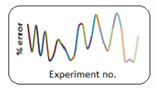
In terms of % error in predictions, Fig. Compares measured and projected values for various forces and surface roughness. The largest inaccuracy in predicting axial force Fx was found to be around 25% for experiment no. 14, whereas it was less than 10% for most of the other experiments (Fig). The highest inaccuracy in forecasts for radial force Fy was rather large at two data points (exp. No. 14 and 17). (Fig). This could be due to a lack of homogeneity in the material or a mistake in the experiment. The inaccuracy was less than 15% for the majority of the other data values. The largest error in prediction for cutting force Fz (Fig) was around 16 percent for experiment no. 21, 13.5 percent for experiment nos. 17 and 25, and around 11 percent for experiment nos. 12 and 13. The error rate for the remaining experiments is substantially below 10%.
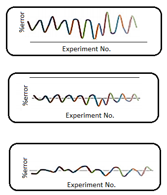
Because of the abrupt character of the measured values utilised to create the model, surface roughness produced substantial error in predictions when modelled with second order fit. This abrupt nature could be related to material inhomogeneity and variations non hardness values across the workpiece. It's also possible that the maximum inaccuracy caused in predicting various forces is the consequence of the same.
1.2.6 Effect of cutting parameters on the forces:
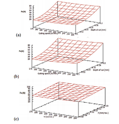
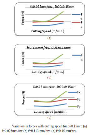
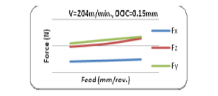
Understanding the effect of cutting parameters on tool forces and surface roughness is critical for fine-tuning the process for the most efficient cutting within the defined range of cutting parameters. The response surface graphs for various force components and surface roughness created were plotted using the regression equations mentioned in the previous section. As shown in figures a, b, and c, the axial forces (Fx) increased as the depth of cut increased, but it had no effect on cutting speed or feed.
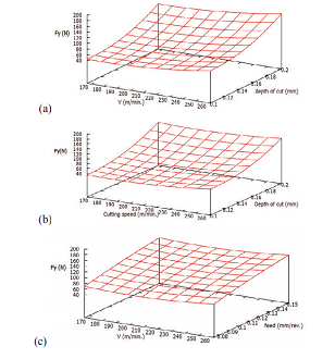
The radial force (Fy) rose as the cut depth grew (fig a and b). At lower feeds, it grew as the speed increased (fig. a), but at higher feeds and deeper cuts, the radial force first decreased, then increased a little (fig. b). In fig. c, the tendency is considerably more obvious. This could be because the workpiece becomes sufficiently thermally softened at high depths of cut and feed that additional increases in cutting speed have no influence on the process. As seen in figures, this might happen within a particular critical range of cutting speed, which in this case is between 170 and 220 m/min.
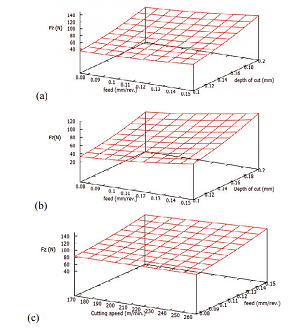
Cutting force component (Fz) rose as feed and cut depth rose. However, in the defined range of machining parameters, it showed indifference to cutting speed. This could be because the work piece material becomes thermally softened and thus more machinable at high feed and speed.
1.2.7 Effect of cutting parameters on surface roughness:
The fluctuation in surface roughness with cutting settings is shown in Figures a, b, and c. For majority of the feed values in the range, the surface roughness increased as the depth of cut rose. However, with low depth cuts, it first reduced and then grew as feed increased. While, for high depth of cut in the selected range, the surface roughness decreased with increase in feed.
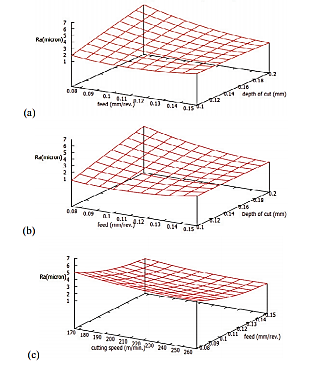
Surface roughness in the turning direction decreased with increased cutting speed, but the roughness value decreased with increased feed, as shown. The cause for this could be that the material was ploughed at a low feed rate. Because of the low feed, the uncut chip thickness would be relatively thin, resulting in ploughing instead of cutting at low feeds, resulting in increased surface roughness. As the feed level rises, the ploughing effect decreases, resulting in a better surface.
1.2.8 Conditions for efficient cutting:
Figures show the examples where the cutting force values were virtually identical to the radial force. These were the most efficient cuts since they demonstrated that cutting used more power than holding the tool in a transverse direction. Figures a, b, and c show that low and moderate cutting speeds in the selected range, as well as a moderate depth of cut, may be the most efficient.
Figure also indicates that by keeping speed and depth of cut in the selected range at moderate levels, the most efficient cut may be attained for practically all feeds. It may be determined that lower to moderate speeds and medium depths of cut of the given parameter range should be employed to accomplish energy efficient machining.
1.2.9 Conclusions:
The most influential parameter determining the three cutting forces was determined to be the depth of cut, followed by the feed. Cutting speed was least important in the axial and radial force models, although it was not significant in the cutting force regression model. The model derived from the investigation was shown to be insignificant for surface roughness predictions. The response surface study revealed that when cutting speed rose, forces first reduced and subsequently increased. It revealed a critical cutting speed range where thermal softening may have occurred, resulting in a reduction in the forces generated. In the range of parameters specified, the most energy efficient cut can be accomplished for practically all feed values specified for relatively lower and moderate cutting speeds with moderate depth of cut.
1.2.10 Tool materials:
Cutting tool capability and overall performance are determined by:
• Cutting tool materials
• Cutting tool geometry
• Appropriate tool selection and application
• The machining environment and conditions
The tool material is the most important of these.
Primary Cutting Tool Materials: Characteristics and Applications
(a) High-Speed Steel (HSS)
The introduction of HSS in roughly 1905 marked a watershed moment in the history of cutting tools.
Many other innovative tool materials, such as cemented carbides, have now supplanted these materials.
And ceramics, which were significantly faster to produce than HSS tools.
The basic composition of HSS is 18% W, 4% Cr, 1%V, 0.7% C and rest Fe.
This HSS tool could only machine (turn) mild steel tasks at a pace of 20 to 30 m/min (which was fairly fast back then). However, HSS is still utilised as a cutting tool material in the following situations:
• Chip formation tools, such as helical twist drills, reamers, gear shaping cutters, hobs, form tools, and broaches, have complex geometry and mechanics.
• Brittle tools, such as carbides and ceramics, are unsuitable for stress loading.
• Small businesses cannot afford more expensive equipment.
• Old or low-powered tiny machine tools are unable of handling high speeds and feeds.
• The tool must be resharpened a certain number of times.
HSS (tools) efficacy and efficiency, as well as their application range, gradually improved over time by enhancing their characteristics and surface quality through.
• Microstructure refinement • Significant amounts of cobalt and vanadium added to boost hot hardness and wear resistance, respectively
• Powder metallurgical manufacturing procedure
• Chemical Vapour Coating of Surfaces with Heat and Wear Resistant Materials (TiC, TiN, etc.)
CVD (Chemical Vapor Deposition) or PVD (Physical Vapor Deposition) (PVD)
The amount of Co and V added, as well as the microstructure and coating refinement, increased.
HSS tools have improved strength and wear resistance, resulting in increased productivity and tool life.
Remarkably.
(b) Stellite
This is a cast alloy of Co (40 to 50%), Cr (27 to 32%), W (14 to 19%) and C (2%). Stellite is
Quite tough and more heat and wear resistive than the basic HSS (18 – 4 – 1) But such stellite as
Cutting tool material became obsolete for its poor grind ability and especially after the arrival of
Cemented carbides.
(c) Sintered Tungsten carbides
The advent of sintered carbides made another breakthrough in the history of cutting tool
Materials.
• Straight or single carbide
First, powder metallurgically produced straight or single carbide tools or inserts were made by combining, compacting, and sintering 90 to 95 percent WC powder with cobalt. The binder Co holds the heated, hard, and wear-resistant WC grains in place, providing the requisite strength and durability.
Toughness. These tools are ideal for machining grey cast iron, brass, and bronze, among other materials.
Short, discontinuous chips, and at cutting speeds two to three times those of HSS
Tools.
• Composite carbides
Because of the rapid accumulation of wear, notably crater wear, caused by diffusion of Co and carbon from the tool to the chip under high stress and temperature bulk (plastic) contact between the continuous chip and the tool surfaces, single carbides are not appropriate for cutting steels.
Another type of carbide called composite carbide has been created for successfully machining steels.
By adding a gamma phase to the WC and Co mix (8 to 20%). The gamma phase is made up of a mixture of TiC and other materials.
Due to their greater stability and resistance to diffusion than WC, TiN, TaC, and NiC, for example, are more diffusion resistant.
Steel has a lower wettability.
• Mixed carbides
Titanium carbide (TiC) is not just more stable than WC, but it's also a lot tougher. As a result, a substantial proportion (5 to 25%) of TiC is added to WC and Co to generate another grade known as mixed carbide for machining ferritic steels that cause intense diffusion and adhesion wear. However, as TiC levels rise,
The toughness of the tools is reduced as a result of the substance. As a result, in order to complete with a light cut but fast speed,
For extensive roughing work at lower temperatures, the tougher grades containing up to 25% TiC are used.
TiC with a lower percentage (5 to 10%) is acceptable for faster speeds.
d) Simple ceramics
The ceramics' inherent high compressive strength, chemical stability, and hot hardness resulted in
Since 1950, we've been producing indexable ceramic tool inserts using powder metallurgy. Alumina is a kind of alumina that (Al2O3)
For better hardness and chemical stability, silicon nitride (Si3N4) is chosen. Si3N4 is more durable.
However, it is more harder to process this time. Because plain ceramic tools are brittle, they had to be replaced.
In general, there are three types of ceramic tool bits available on the market:
• Plain alumina with trace additions – these white or pink sintered inserts are cold pressed and primarily used to machine cast iron and comparable materials at speeds of 200 to 250 m/min.
• Alumina; hot pressed, black colour, hard and strong, with or without additions – utilised for steel and cast iron machining at VC=150 to 250 m/min
• Cold or hot pressed carbide ceramic (Al2O3+ 30% TiC), black colour, quite robust and sufficient difficult – 150 to 200 m/min machining of hard cast irons and plain and alloy steels. However, until their strength and hardness could be improved, such brittle plain ceramic tools should be used. Since 1970, it has steadily deteriorated as a result of being restricted to
• Only machining of soft cast irons and steels without interruption
• Cutting velocity is relatively high, but only in a short range (200–300 m/min).
• Necessitating the use of extremely stiff machine tools
The introduction of coated carbide capable of cutting cast iron and steels at high speeds revolutionised the industry.
Ceramics became almost obsolete as a result.
(e)Cermets
These sintered hard inserts are created by mixing ‘cer' from ceramics such as TiC, TiN, orn(or)TiCN with ‘met' from metals such as Ni, Ni-Co, Fe, and so on. The contemporary era began around 1980.
TiCN, which is consistently more expensive, is used to make cermets that function significantly better.
Wear-resistant, less porous, and simpler to manufacture. The distinguishing characteristics of such cermets, in
In comparison to sintered tungsten carbides, the following are:
• The grains are formed of TiCN (rather than WC) and Ni or Ni-Co and Fe as a binder (rather than WC).
Co)
• Harder, more chemically stable, and thus more resistant to wear.
30
• More brittle and less resistant to heat shock
• The percentage of binder metal fluctuates between 10% and 20%.
• Unlike coated carbide inserts, the cutting edge sharpness is retained.
• Can manufacture steels at a higher cutting speed than tungsten carbide, even when coated
In the case of light cuts, carbides are used.
Modern TiCN-based cermets with bevelled or slightly rounded cutting edges are ideal for a variety of applications.
Steels, stainless steels, and edges are appropriate for finishing and semi-finishing at higher speeds.
Are not appropriate for jerky interrupted machining of aluminium and related materials.
Materials. The features are still being improved through research and development.
As well as the performance of cermets
(f)Coronite
The characteristics and performance of HSS tools might have been significantly enhanced by microstructure refinement, the powder metallurgical process of manufacture, and other factors, as previously discussed.
Covering on the surface Coronite, a one-of-a-kind tool material, was recently developed for
Tiny and medium-sized drills, milling cutters, and other tools that were previously unavailable
Basically, it's made of HSS. Coronite is created by mixing high-strength steel (HSS) with a variety of other materials.
Heat and wear resistance are provided by tungsten carbides. The TiCN particles are micro fine consistently distributed throughout the matrix
The coronate-based tool, unlike solid carbide, is made up of three layers.
• The HSS or spring steel core in the centre
• A coronite coating that is around 15% of the tool's diameter thick.
• A TiCN PVD coating that is 2 to 5 m thick.
These tools are not only more productive, but they also produce higher-quality products. The coronite is a mineral that is found in nature.
HSS tools were outperformed by tools manufactured by hot extrusion followed by PVD-coating of TiN or TiCN.
Cutting pressures, tool life, and surface polish are all factors to consider.
High-performance ceramics (g) (HPC)
Ceramic tools outperform sintered carbides in terms of hot hardness, chemical stability, and heat and wear resistance, but they lack fracture toughness and strength. Last but not least,
During the last few years, there have been significant advances in strength and toughness, as well as overall performance.
Several factors could have made ceramic tools conceivable, including:
•Al2O3ceramics' sinterability, microstructure, strength, and toughness were all improved to some extent by combining TiO2 and MgO
• Toughening the transformation by adding the right amount of partially or fully stabilised Al2O3 powder with zirconia
• Isostatic and hot isostatic pressing (HIP) — both of these methods are quite successful, but they are also highly expensive.
• Using a good sintering procedure to introduce nitride ceramic (Si3N4) – this material is highly strong. In machining steels, robust but prone to built-up-edge formation
• SIALON development - determining the favourable effects of Al2O3 and Si3N4
• Adding carbide, such as TiC (5-15%), to Al2O3 powder to add toughness and heat resistance conductivity
• SiC whiskers were used to reinforce oxide or nitride ceramics, increasing strength and hardness and the tool's life, as well as its productivity, have increased dramatically. However, the creation and application of this one-of-a-kind product
Handling a tool requires extra caution.
•Toughening Al2O3 ceramic by including a suitable metal, such as silver, which also has thermal properties.
This new and affordable instrument is still in the experimental stage due to its conductivity and self-lubricating properties.
The improved attributes of the one-of-a-kind high-performance ceramic tools, particularly the whisker and the comb,
They were able to mill structural steels at speeds of up to 500 m/min using zirconia-based kinds.
Intermittent cutting at moderately high rates, feeds, and depths of cut are also possible. Such devices are also available.
Found that it is possible to process considerably harder and stronger steels efficiently and effectively.
Ceramic tools made of nitride
Tools made of plain nitride ceramics
Nitride (Si3N4) ceramic tools are more resistant to corrosion than simple alumina ceramics.
Due to greater bending strength, hardness, and toughness, fractures by mechanical and thermal shocks
Increased conductivity As a result, such a tool appears to be better suited to rough and interrupted cutting.
Except for steels, a variety of materials generate rapid diffusional wear and the production of BUE. The
The wear resistance and fracture toughness of nitride ceramic tools should be improved further.
Zirconia is added, and the completed tools are coated with high-hardness alumina and titanium.
Compound High-density nitride ceramics are difficult to compact and sintered.
With the help of reaction bonding' and 'hot pressing,' this difficulty can be mitigated to some extent.
SIALON's equipment
An adequate blend of Al2O3 and Si3N4 powders was hot pressed and sintered to produce an adequate combination of Al2O3 and Si3N4 powders.
SIALON is an exceptional composite ceramic tool that is exceptionally hot hard, strong, and wear resistant.
Steel and cast irons can be machined at high rates (250–300 m/min) with these tools. But the tool life is reduced by fast diffusion when machining steels with such tools at too high speeds Nitride tools with SiC reinforcement the toughness, strength, and thermal conductivity of nitride, as well as its overall performance
Ceramics could be significantly improved by adding SiC whiskers or fibres in the range of 5 to 25% by volume Crack bridging, crack deflection, and fracture toughness are all added by SiC whiskers.
Pull-out of fibre Such tools are incredibly expensive, but they are ideal for high-volume production. Machining of a variety of soft and hard materials, even when cutting is interrupted toughened alumina (ZTA) is a zirconia (or partially stabilised zirconia) ceramic. These ZTAs are more extensively applicable due to their increased strength, TRS, and toughness.
In machining steels and cast irons, it is more productive than plain ceramics and cermets. a very fine powder in a proportion of ten to twenty volume percentages, partly stabilised zirconia (PSZ) is combined.
Either cold pressed and sintered at 1600 – 1700o with pure alumina
C or isostatically hot pressed (HIP) at a temperature and pressure that is appropriate. The metastable phase transformation during the cooling of the composite (Al2O3+), tetragonal zirconia (t-Z) transforms into monoclinic zirconia (m-Z).
After sintering or HIP, and during polishing and machining, ZrO2) inserts impart the appropriate properties. Through volume expansion (3–5% ) and generated shear strain, strength and fracture toughness can be increased. Proper particle size and sintering control have increased their hardness even more.
The density, strength, and hot hardness of ZTA tools are increased by hot pressing and HIP, while the density, strength, and hot hardness of ZTA tools are not increased.
At lower cutting speeds, the process becomes more expensive, and tool performance suffers. However Steel and cast iron can be machined at speeds ranging from 150 to 500 m/min using such ceramic tools. Alumina SiC whiskers strengthen the ceramic.
The features, capabilities, and range of applications of The performance of alumina-based ceramic tools has increased dramatically as a result of a significant increase in the amount of alumina used.
Without losing hardness, fracture toughness (2.5 times), TRS, and bulk thermal conductivity Mechanically strengthening the brittle alumina matrix with exceptionally strong fibres improves wear resistance.
With silicon carbide whiskers that are stiff The strong, thermally conductive, and randomly oriented Crack deflection and crack-bridging are the key ways that whsikers improve strength and toughness.
In addition, the temperature differential within the tool can be reduced. Following the composition's optimization, Such tools have been shown to be effective and efficient in terms of processing and tool geometry.
Machine a wide range of materials at a wide range of speeds (250 – 600 m/min), even under extreme conditions a lot of chips However, the production of whiskers necessitates extreme caution and precision.These tools are more expensive than tools made of zirconia toughened ceramic.
Alumina ceramic with silver toughening
Since 1990, the use of metal particles to toughen alumina has become a hot topic.
The notion was first mentioned in the 1950s. Alumina-metal composites have mostly been investigated using
Metals such as aluminium, nickel, chromium, molybdenum, iron, and silver are added. When compared to metals such as zirconia and carbides have been discovered to provide additional toughness in alumina ceramics. Again
The silver-toughened ceramics can be more durable than other metal toughened ceramics.
Simpler and more cost-effective process approaches, such as pressure-less sintering an without the ability to control the atmosphere All of these putative silver-toughened alumina properties.Ceramics have already been used to make certain important parts of autos and other vehicles.
The development and usage of silver-toughened alumina for cutting tools is currently being researched.The addition of metal to the alumina matrix causes it to toughen.
The metal grains, in particular,are responsible for crack deflection and crack bridging. Silver is added to the mix aids by enhancing the tool's thermal conductivity and providing self-lubrication through silver traces that seeps out of the pores and makes its way to the chip tool interface HPC tools like this can a machine with a high MRR and VC (250–400 m/min) and a long tool life, especially in low light.
Milling is a type of interrupted cutting. Steels can also be machined with these tools at speeds ranging from slow to fast. Cutting speeds of 200 to 500 m/min are common. Cubic Boron Nitride (h) Cubic boron nitride is the hardest material currently available, second only to diamond. CBN, in the form of compacts, was only introduced as a cutting tool in 1970 and afterwards. It's created by a 0.5–1 mm layer of polycrystalline cubic boron nitride is bonded to a cobalt-based carbide At extremely high temperatures and pressures, a substrate is created. It is inert and has a high hardness and toughness at high machining rates, fracture toughness It performs admirably when it comes to grinding any type of material.
High-hardness, high-strength material. Extreme durability, chemical and thermal resistance CBN cutting tool inserts for high material strength were developed due to their stability and wear resistance. Precise machining and a high removal rate (MRR) ensure exceptional surface integrity.
These one-of-a-kind tools are useful and advantageous in a wide range of machining tasks. Materials ranging from high carbon and alloy steels to non-ferrous metals and alloys, as well as unusual metals such as Ni-hard, Inconel, Nimonic, and many other non-metallic materials that are tough to work with.
Machining with traditional tools It can withstand temperatures of up to 1400°C. The key phrase is when machining grey cast iron, CBN has a speed range of 300 to 400 m/min. Ranges of speeds for other.
The following are the materials:
• 80–300 m/min for hard cast iron (> 400 BHN)
• Super alloys (more than 35 RC): 80–140 m/min
• Hardened steels (RC more than 45): 100–300 m/min
The most essential aspect that impacts the performance of CBN inserts, other from speed, is the material cutting edge preparation CBN tools with an honed or chamfered edge are ideal. Preparation, especially for cuts that are stopped CBN tools, like ceramics, are only accessible in limited quantities.
Inserts that can be indexed. Its only drawback is its exorbitant price.
Diamond Tools I
Diamond crystals, whether natural or synthetic, are utilised as cutting tool tips and edges. Natural single crystal is employed in a variety of applications because to its exceptional toughness and sharp edges.
Especially when high precision and accuracy are required. The following are some of their primary applications:
• Single-point cutting tool tips and tiny drills for machining non-ferrous metals at high speeds ceramics, plastics, composites, and other difficult-to-machine materials, as well as effective machining of these materials
• Drill bits for mining, oil exploration, and other applications.
• Glass, stone, ceramics, FRPs, and other materials can be cut and drilled with this tool.
• Extrusion and wire drawing dies
• For important grinding, super abrasive wheels are used. Natural diamonds have a limited supply, rising demand, high cost, and easy cleavage, all of which need a new approach a more trustworthy diamond supply Artificial diamonds were invented and manufactured as a result of this grits using an ultra-high temperature and pressure synthesis technique, allowing for large-scale production. Diamond grits are manufactured with some control over size, shape, and friability for a variety of applications.
Diamond that is polycrystalline (PCD)
A layer of fine grain size (0.5 to 1.5 mm) is applied to the polycrystalline diamond (PCD) tools. Diamond particles that are randomly orientated and sintered with a suitable binder (typically cobalt) and then metallurgically attached to a suitable substrate, such as cemented carbide or Si3N4 inserts PCD demonstrates good wear resistance, maintains a sharp edge, produces low friction in the cut.
The material had a high fracture strength and good thermal conductivity. PCD is caused by these characteristics. Long-life tooling or unusual and high-speed machining of soft, non-ferrous materials Advanced composites and metal-matrix composites, superalloys (aluminium, magnesium, copper, etc.), superalloys (aluminium, magnesium, copper, etc. ), superalloys.
Non-metallic materials and alloys are examples of non-metallic materials. PCD is very well adapted to abrasive materials (e.g., metals).Drilling and reaming metal matrix composites), where it outlasts carbides by 100 times. Because of the high solubility of diamond, PCD is not normally advised for ferrous metals. (carbon) in these materials when they're heated up. However, under some circumstances, they can be used to manufacture certain of these materials; for example,
Light cuts, for example, can be produced successfully in grey cast iron. The main benefit of such a because of the finer microstructure and random orientation of the particles, the PCD tool has a higher toughness decreased cleavage and granules However, such a one-of-a-kind PCD has some drawbacks, such as:
• Expensive tooling
• Cobalt, a binder, is present, reducing wear resistance and thermal stability.
• Complex tool forms, such as a built-in chip breaker, is not possible to produce.
• Size restrictions, especially when creating tools with very small diameters
The limitations of polycrystalline diamond tools described above have practically been overcome.
Diamond-coated tools are being developed.
Carbide tools with diamond coating
Continuous effort has been made since the advent of low-pressure diamond synthesis from gaseous phase.
The decision was made to use thin film diamond in the realm of cutting tools. These are typically utilised as a thin layer of protection.
Diamond films made by CVD technique that are thin (50 m) or thick (> 200 m) for cutting tools, Abrasive Jet Machining (AJM) and grinding dies, wear surfaces, and even abrasives.The film is applied directly on the tool's surface. Thick film (> 500 m) is grown on a simple substrate.The primary substrate is removed and brazed to the actual tool substrate, and the secondary substrate is brazed to the actual tool substrate.Whether by dissolving it or some other method. Inserts, drills, and other items are made with thick film diamond.
Reamers, end mills, and routers are all examples of machine tools. Single diamond crystals are less popular than CVD coatings.
PCD is mostly used for:
• Free of binder, better hardness, and heat and wear resistance than PCD and
Properties adjacent to diamond mines
• Exceptionally pure, thick, and devoid of single crystal cleavage
• Allows for a larger range of tool sizes and shapes, and can be deposited on any tool shape.
• It's a lot less expensive.
However, improving and ensuring the performance of thin film CVD diamond coated tools is a challenge.
(carbide, nitride, ceramic, SiC, and other materials) in terms of tool life, dimensional accuracy, and surface finish
Job completion necessitates:
1. The diamond layer is well-bonded.
2. Adequate film properties, such as wear resistance, micro hardness, edge coverage, and edge sharpness consistency of thickness and sharpness
3. The ability to offer the needed work surface finish for specific applications.
While CBN tools are possible and profitable for high-speed machining of hard and strong steels and other materials, they are not ideal.
Diamond tools are highly effective for machining stones, slates, glass, and other comparable materials. Ceramics, composites, fibre reinforced plastics, and nonferrous metals, particularly those that are sticky and BUE formers
Aluminum and its alloys, for example. CBN and Diamond tools are also commonly utilised for ultra-fine work.
Precision, as well as micro and nano machining, are all available.
1.2.11 Chip Formation:
The goal of every milling and turning operation is to eliminate material in order to attain the completed part's specified dimensions. Although milling and turning appear to use drastically different procedures, the fundamental principle of material removal by chip production is the same in both.
The example of a planning machine is possibly the easiest to imagine to demonstrate the principle of chip creation. Planning will not be detailed in depth; suffice it to state that the tool and workpiece move along a linear path, and the tool generates chips in a manner that is basically similar to milling and turning.
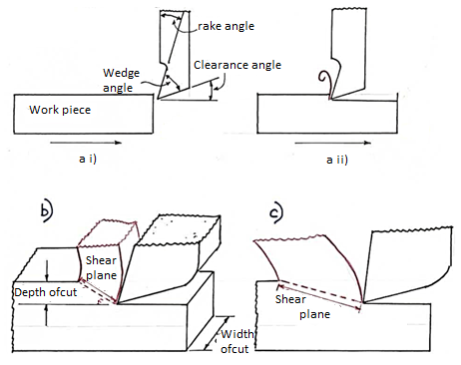
A planer is shown in Fig in a side view, relative to feed direction, before the tool and work piece are engaged. The rake and clearance angles are two of the most significant variables to consider in chip production; note that the wedge angle formed is a direct link between these two angles; that is, the bigger the total of clearance and rake angle, the smaller the wedge angle.
The clearance angle ensures that just the tool's cutting edge makes contact with the work piece, and that the tool's rear, or heel, does not rub against the finished surface, deteriorating the finish and requiring more power.
The lower the wedge angle, the weaker and less able to disperse heat is the tip of the tool, as shown in. As a result, the ‘perfect' rake and clearance angles for a given material are frequently a compromise between outright cutting ability and acceptable strength.
Different sorts of chips can form under various cutting conditions, such as varied depths of cut, work piece material, rake angles, cutting speed, and machine rigidity. Continuous and discontinuous chips are the two primary types of chips.
1.2.12 Merchant theory:
The notion of minimum energy underpins this hypothesis. According to this theory, the angle will take on a value that will result in the least amount of cutting labour.
Because the work done is only dependent on the cutting force component Fp, the angle should be set so that Fp is at a minimum for the provided.
From the diagram of a merchant's circle,


Where Z= mean shear stress
B= width of the chip
t= uncut chip thickness.
Shear will occur when the shear strength on the plane described by angle is totally equal to the shear strength ′ of the materials.
For a simple analytic it is assumed to be constant.

For minimum Fp


Which gives a minimum value, or,

1.2.13 Cutting fluid:
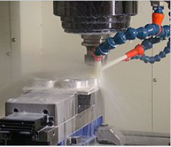
Cutting fluid is a specialised coolant and lubricant for metalworking processes such as machining and stamping. Cutting fluids include oils, oil-water emulsions, pastes, gels, aerosols (mists), and air or other gases, among others. Petroleum distillates, animal fats, plant oils, water and air, or other basic materials are used to make cutting fluids. Cutting fluid, cutting oil, cutting compound, coolant, or lubricant are all terms that might be used depending on the context and the type of cutting fluid being addressed.
Depending on the workpiece material, most metalworking and machining processes can benefit from the use of cutting fluid. Cast iron and brass are common exceptions, as they may be machined dry (though this is not true of all brasses, and any machining of brass will likely benefit from the presence of a cutting fluid).
A good cutting fluid should be able to do the following things:
• Maintain a constant temperature for the workpiece (critical when working to close tolerances). Extremely hot or alternating hot-and-cold temperatures are not recommended.
• Lubricate the cutting edge and reduce tip welding to extend the life of the cutting tip.
• Ensure the safety of those handling it (toxicity, bacteria, fungi) as well as the environment when it is disposed of.
• Protect machine parts and cutters against rust.
1.2.14 Temperature effect:
Causes, consequences, assessment, and control of cutting temperature
Determine the cutting temperature value.
•Analytical techniques
•Experimental approaches
Heat generation and temperature development in machining: sources and causes
Heat is created at the cutting tip during machining from three sources, as shown in Fig.
Those sources and causes of development of cutting temperature are:
• Primary shear zone (1), where the majority of the energy is converted to heat
• Secondary deformation zone (2), where additional heat is generated owing to rubbing and/or shear at the chip – tool interface
• Worn out flanks (3), due to rubbing between the tool and the finished surfaces
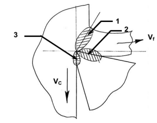
Sources of heat generation in machining
The chip, cutting tool, and blank all share the heat generated. The distribution of that heat is determined by the tool's configuration, size, and thermal conductivity, as well as the cutting situation. The highest amount of heat is represented in Fig.
The chip was carried away by the current. The tool absorbs 10 to 20% of the overall heat, and it also absorbs some of the heat.
In the blank, heat is absorbed. The chip shares heat as cutting velocity increases.
Increasingly.
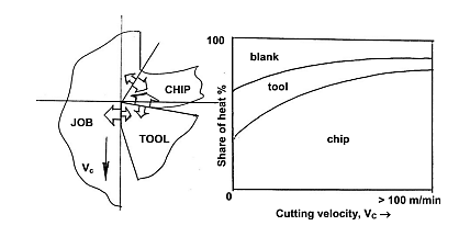
(ii) The impact of high cutting temperatures on the tool and the task.
Cutting temperatures, especially when they are high, have a negative impact on both the tool and the project. The chips are responsible for a large amount of the heat dissipation. However, this is not the case.
Because chips are tossed away, it doesn't matter. As a result, efforts should be undertaken to ensure that the chips are removed.
More and more heat, leaving only a small quantity of heat to destroy the instrument and the job
High cutting temperatures may have negative consequences on the cutting tool (edge).
• Faster tool wear, resulting in shorter tool life
• Cutting edge plastic deformation if the tool material is not sufficiently hot-hard as well as hot-strong owing to thermal shocks, thermal flaking and fracturing of the cutting edges shape with a built-up edge
The following are some of the possible negative consequences of cutting temperature on the machined job:
• Job dimensional inaccuracies caused by thermal distortion and expansion-contraction during and after machining.
• Surface oxidation, fast corrosion, and burning, among other things.
• Surface/subsurface induction of tensile residual stresses and microcracks.
However, in many cases, the high cutting temperature aids in minimising the size of the cut by softening or decreasing the shear pressures and reducing power usage to some level front of the cutting edge, the work material's strength. To achieve or improve such a benefit, material for the upcoming work. The cutting zone is frequently heated from the outside. This method is effective.
Hot Machining is a term that refers to the process of machining work materials that are extremely hot.
High manganese steel, Hadfield steel, Nihard, Nimonic, and other hard and hardenable steels
Cutting temperature determination
To facilitate cutting, the magnitude of the cutting temperature must be known or evaluated.
• Evaluation of machinability, which is primarily determined by cutting forces, temperature, and tool life.
• Cutting tool design and selection
• Determine the impact of different machining parameters on cutting temperature.
• appropriate cutting fluid selection and application
• Temperature distribution analysis in the chip, tool, and task.
The temperatures which are of major interests are:
 : Average shear zone temperature
 : Average (and maximum) temperature at the chip-tool interface
 : Temperature at the work-tool interface (tool flanks)
 : Average cutting temperature
Cutting temperature can be determined by two ways:
• Analytically – if available or possible, using mathematical models (equations). This procedure is easy, rapid, and low-cost, however it is less exact and accurate.
• This method has been shown to be more accurate, precise, and reliable in tests.
Analytical estimation of cutting temperature, 
Average shear zone temperature,
Equation(s) have to be developed for the purpose. One simple method is presented here.
The cutting energy per unit time, i.e., gets used to cause primary shear and to overcome friction at the rake face as,

Where,  = slip velocity along the shear plane
And  = average chip – velocity

Equating amount of heat received by the chip in one minute from the shear zone and the heat contained by that chip, it appears,

Where, A = fraction (of shear energy that is converted into heat)
 = fraction (of heat that goes to the chip from the shear zone)
J = mechanical equivalent of heat of the chip / work material
 = volume specific heat of the chip
 = ambient temperature
 = cross sectional area of uncut chip =
Therefore, 

Generally, A varies from 0.95 to 1.0 and q from 0.7 to 0.9 in machining like turning.
Average chip – tool interface temperature, 
Using the two dimensionless parameters,  and
and  and their simple relation (Buckingham),

Where  and
and
 = specific cutting energy
 = volume specific heat
λ= thermal conductivity
 = a constant
n = an index close to 0.25
Therefore 
Rom the known other machining parameters, one may determine the approximate value of average using equation 3.6.
Experimental methods of determination of cutting temperature
Among θs, θi, and θf, θi is obviously the highest one and its value is maximum almost at the middle of the chip – tool contact length. In most cases, experimental procedures yield the average or maximum value of i. Some approaches also allow for an equal temperature distribution in the chip, tool, and job at the cutting zone.
The feasible experimental methods are:
• Calorimetric method — easy and inexpensive, but imprecise and only provides a grand average value.
• Decolorizing agent - around the cutting point, some paint or tape that changes colour with temperature is pasted on the tool or work; as a result, the colour of the chip (steels) can sometimes indicate cutting temperature.
• Tool-work thermocouple – simple and low-cost, but only offers average or maximum values.
• Thermocouple technology that moves
• Thermocouple method with embedded thermocouples
• Working with a compound tool
Hardness and structural changes indirectly
• Photo-cell method
• Method for detecting infrared rays
The aforesaid methods are all feasible but vary w.r.t. Accuracy, preciseness and reliability as well as complexity or difficulties and expensiveness. Some of the most often utilised approaches are briefly discussed here.
Tool work thermocouple technique
Fig. Shows the principle of this method.
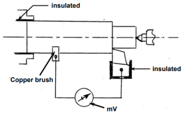
Two junctions in a thermocouple connect two dissimilar but electrically conducting metals. When one of the junctions is heated, the temperature differential between the hot and cold junctions produces a proportionate current, which a millivoltmeter detects and measures. The tool and the task are two dissimilar metals in machining like turning, and the cutting zone serves as the hot junction. After comprehensive calibration, the average cutting temperature is calculated from the mV in order to determine the exact relationship between mV and cutting temperature.
Fig. Typically shows a method of calibration for measuring average cutting temperature,  , in turning steel rod by uncoated carbide tool.
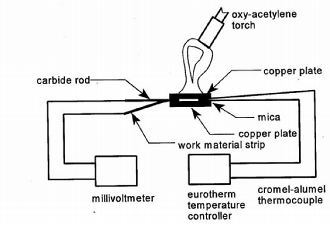
Moving thermocouple technique
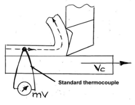
This straightforward method, depicted schematically in Fig, allows you to track the temperature of a flowing chip before, during, and immediately after it forms. The temperature is measured in mV using a bead of standard thermocouple, such as chrome-alumel, brazed on the side surface of the layer to be removed from the work surface.
Embedded thermocouple technique
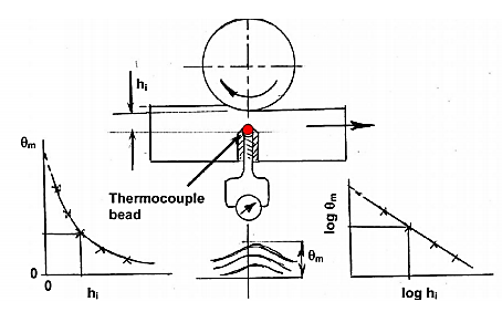
Embedded thermocouples can be used in activities like as milling and grinding where the preceding approaches are ineffective. The principle is depicted in Figure. The conventional thermocouple measures the temperature of the job at a depth of h from the cutting zone. When the thermocouple bead is closest (slightly offset) to the grinding zone, the temperature recorded in an oscilloscope or strip chart recorder reaches its maximum. As the grinding progresses, the depth, h, gradually lowers with each grinding pass, while the temperature value also rises, as shown in Fig. Hi has to be zero to achieve the temperature exactly at the surface, i.e., the grinding zone, which is not achievable. To acquire the real grinding zone temperature, the vs h curve must be projected up to h= 0. The log–log diagram makes extrapolation easier and more precise.
Measurement of chip-tool interface temperature by compound tool
A conducting tool component (carbide) is implanted in a non-conducting tool in this procedure (ceramic). The tool work thermocouple is made up of the conducting piece and the job, as shown in Fig, and it measures temperature at the place () of the carbide strip. By gradually lowering the tool flank by grinding, it may be measured along the whole chip-tool contact length. Prior to that, calibration must be completed as usual.
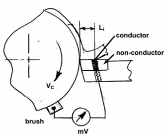
Photo-cell technique
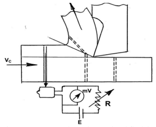
As seen in Fig, this unique methodology allows for precise temperature measurement along the shear zone and tool flank. When a cell, such as a PbS cell, is subjected to heat radiation, its electrical resistance changes. The amount of resistance change is proportional to the temperature of the heat radiating source and is measured in voltage, which is calibrated to the source temperature. The cell only begins to receive radiation through the little hole when it approaches the shear zone, when the hole at the higher end faces a heated surface, as shown in Fig. The hole continues to receive radiation and measure temperature until it passes through the entire shear zone and finally the tool flank.
Infra-red photographic technique
This cutting-edge method involves capturing an infrared snapshot of the tool's, chip's, and/or job's hot surfaces to determine temperature distribution. Before that, proper calibration must be completed. Any machining parameter that affects cutting temperature causes the fringe pattern to vary quickly.
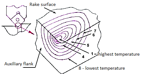
Role of variation of the various machining parameters on cutting temperature
The magnitude of cutting temperature is governed or controlled in some way by all of the machining factors, such as:
• Work material: - Specific energy requirement
- Ductility
- Thermal properties (λ,  )
)
• Process parameters: - Cutting velocity ( )
)
- Feed ( )
)
- Depth of cut (t)
• Cutting tool material: - Thermal properties
- Wear resistance
- Chemical stability
• Tool geometry: - Rake angle (γ)
- Cutting edge angle (φ)
- Clearance angle (α)
- Nose radius (r)
• Cutting fluid : - Thermal and lubricating properties
- Method of application
Many researchers studied, mainly experimentally, on the effects of the various parameters on cutting temperature. A well established overall empirical equation is,

Where,  = a constant that is primarily determined by the materials used in the work tools Equation clearly shows that among the process factors, has the greatest impact, whereas t has a negligible impact. Cutting temperature is also influenced by tool shape. Equation shows that by lowering the principal cutting edge angle and increasing the nose radius, r, the can be lowered. Aside from that, the tool rake angle, and thus the inclination angle, have a big impact on the cutting temperature.
Increase in rake angle will reduce temperature by reducing the cutting forces but too much increase in rake will raise the temperature again due to reduction in the wedge angle of the cutting edge.
Cutting fluid selection and application help lower cutting temperature by cooling and lubricating the cutting surface.
Control of cutting temperature
High cutting temperatures have already been shown to be deleterious in a number of ways. As a result, it's critical to keep the cutting temperature under control or as low as feasible.
The following general methods can be used to adjust cutting temperature to varied degrees:
• correct material and shape of cutting tool(s) selection
• optimum combination selection without sacrificing MRR
• appropriate cutting fluid selection and application
• If necessary and practicable, use of a particular technique.
Basic methods of controlling cutting temperature
Cutting temperature, especially when it is very high, is known to be exceedingly harmful to both cutting tools and machined items, and so must be regulated, i.e. reduced as much as possible without sacrificing productivity or product quality.
The following are some of the most common methods for reducing machining temperature and its negative effects:
• Proper cutting tool selection; material and geometry
• Proper cutting velocity and feed
• Proper cutting fluid selection and application
Selection of material and geometry of cutting tool for reducing cutting temperature and its effects
Depending on the work material, the cutting tool material may play a considerable influence in lowering the cutting temperature.
As for example,
• HSS and carbide tools with PVD or CVD coatings allow for lower cutting temperatures by minimising friction at the chip-tool and work-tool interfaces.
• When high-speed machining of steels is done using CBN tools, which create lower cutting forces while maintaining precise geometry due to their great hardness and chemical resilience, less heat and cutting temperature is generated.
• If the heat conductivity of ceramic tools is improved, the cutting tool temperature drops even further (by adding thermally conductive materials like metals, carbides, etc in Al2O3or Si3N4)
• Cutting temperature can be adjusted in a significant degree by selecting the right tool shape in the following ways:
• A large positive tool–rake reduces heat and temperature generation by reducing cutting forces, but an excessive increase in rake weakens the cutting edges mechanically and thermally.
• Using a compound rake, especially with a chip–breaker, reduces heat and temperature by reducing cutting forces and friction.
• Cutting temperature falls when the major cutting edge angle decreases, even with the same quantity of heat output.

Nose radius of single point tools not only improves surface finish but also helps in reducing cutting temperature to some extent.
1.2.15 Wear:
Mechanisms and pattern (geometry) of cutting tool wear
To regulate tool wear, one must first comprehend the various mechanisms of wear that the cutting tool experiences under various conditions. Cutting tool wear is caused by the following mechanisms:
1. Mechanical wear
a. Thermally insensitive type; like abrasion, chipping and de-lamination
b. Thermally sensitive type; like adhesion, fracturing, flaking etc.
2. Thermo chemical wear
a. Macro-diffusion by mass dissolution
b. Micro-diffusion by atomic migration
3. Chemical wear
4. Galvanic wear
When the tool material possesses chemical affinity or solid solubility towards the work material, material from the tool at its rubbing surfaces, notably at the rake surface, gradually diffuses into the flowing chips, either in bulk or atom by atom. As the temperature in the cutting zone rises, so does the rate of such tool wear.
When the cutting temperature rises rapidly due to high cutting velocity and high work material strength, diffusion wear takes over. If the tool material is not chemically stable enough against the work material and/or ambient gases, chemical wear, such as grooving wear, can occur.
When both the work tool materials are electrically conductive, the cutting zone temperature is high, and the cutting fluid acts as an electrolyte, galvanic wear based on electrochemical dissolution is rare.
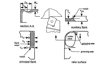
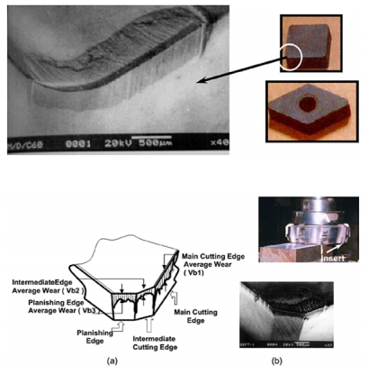
The typical wear pattern or geometry of turning and face milling inserts is seen in Fig. Respectively.
In addition to the tool's eventual failure, the growing tool-wear has the following consequences:
Dimensions deviation and surface roughness increase mostly owing to tool-tip and auxiliary flank wear (Vs) strange noises and vibrations deterioration of surface integrity. The tool tip is mechanically weakened.
(iii) Essential properties for cutting tool materials
Cutting tools must be able to satisfy the increasing demands for increased productivity and efficiency, as well as machine the unusual materials that are emerging as a result of rapid advances in science and technology. To resist or delay the events that contribute to random or early tool failure, today's and tomorrow's cutting tool materials must have the following properties:
i. High compressive, tensile, and TRA mechanical strength
Ii. Fracture toughness should be high or adequate.
Iii. Abrasion resistance due to increased hardness
Iv. High hot hardness to minimise wear rate at increased temperatures and resist plastic deformation
v. Chemical inertness or chemical stability in the presence of work materials, ambient gases, and cutting fluids
Vi. Adhesion and diffusion resistance
Vii. Thermal conductivity — low at the surface to resist heat entry and high in the core to quickly disperse heat.
Viii. Stiffness and heat resistance
Ix. Manufacturability, accessibility, and affordability.
1.2.16 Tool Life:
Definition –
The amount of satisfactory performance or service provided by a new tool or a cutting point until it is pronounced failed is referred to as tool life.
There are two methods to define tool life:
a) The amount of time (period) that a new cutting tool (or point) performs satisfactorily before needing to be replaced or reconditioned. Mechanical breakage or rapid plastic deformation rarely cause contemporary tools to fail prematurely or abruptly. Those fail mostly due to the wear process, which rises slowly with machining time. In this scenario, tool life refers to the amount of real machining time that a new tool may work before reaching the stipulated tool wear limit. The machining time until flank wear, VB, reaches 0.3 mm, or crater wear, KT, reaches 0.15 mm, determines tool life.
b) The period of time a new tool may give good service or acceptable output before it needs to be replaced or reconditioned.
Evaluation of the tool's lifespan Tool life is always measured or reported in terms of machining time in minutes, however in some industries, other methods, such as machining time in seconds, are also used to analyse tool life, depending on the scenario.
• the number of pieces of work that have been machined
• total amount of waste removed
• The total length of the cut
Measurement of tool wear
The following are the numerous methods:
i. By a one-time loss of tool material in volume or weight – this is a rudimentary method that is generally relevant to essential tools such as grinding wheels.
Ii. By grooving and indentation method – the difference in length of the groove or indentation outside and inside the worn area is used to estimate wear depth in this approach.
Iii. Utilising an optical microscope with a micrometre - this is a very common and effective technique.
Iv. SEM (scanning electron microscope) - utilised for extensive analysis, both qualitative and quantitative
v. Talysurf, which is particularly good for shallow crater wear.
Taylor’s tool life equation
The level of machining parameters, such as cutting velocity (V C), feed (S 0), and depth of cut (D 0), determine the wear and hence tool life of any tool for any work material (t). Cutting velocity has an impact on the maximum and minimum cut depths.
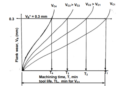
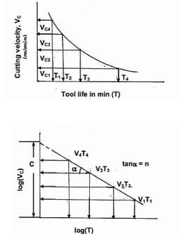
In Fig, the typical pattern of cutting tool wear (mostly VB), the basis of determining tool life, and its relationship to cutting velocity are graphically depicted.
The tool life obviously decreases with the increase in cutting velocity keeping other conditions unaltered as indicated in Fig.
If the tool lives, ,
, ,
,  ,
, etc are plotted against the corresponding cutting velocities,
  ,
,  ,
,  ,
,  etc as shown in Fig, a smooth curve like a rectangular hyperbola is found to appear. When F. W. Taylor plotted the same figure taking both V and T in log-scale, a more distinct linear relationship appeared as schematically shown in Fig.
With the slope, n and intercept, c, Taylor derived the simple equation as

Taylor's tool life exponent is denoted by the letter n. The values of both ‘n' and ‘c' are largely determined by the materials used in tooling and the cutting environment (cutting fluid application). C's value is likewise influenced by undertaken limiting value (i.e., 0.3 mm, 0.4 mm, 0.6 mm etc.).
Modified Taylor’s Tool Life equation
Only the influence of variation in cutting velocity, V C, on tool life has been examined in Taylor's tool life equation. In practise, however, feed (so) and cut depth (t) variations have a role in tool life to some extent.
The Taylor's tool life equation has been adjusted to include the impact of all of those parameters:

Where, TL = tool life in min
 ⎯a constant depending mainly upon the tool – work materials and the limiting value of
  undertaken.
x, y and z ⎯exponents so called tool life exponents depending upon the tool – work materials and the machining environment.
Generally, x > y > z as affects tool life maximum and t minimum.
The values of the constants, CT, x, y and z are available in Machining Data Handbooks or can be evaluated by machining tests.
1.3.1 Chip Formation
The goal of every milling and turning operation is to eliminate material in order to attain the completed part's specified dimensions.
Although milling and turning appear to use drastically different procedures, the fundamental principle of material removal by chip production is the same in both.
The example of a planning machine is possibly the easiest to imagine to demonstrate the principle of chip creation. Planning will not be detailed in depth; suffice it to state that the tool and workpiece move along a linear path, and the tool generates chips in a manner that is basically similar to milling and turning.
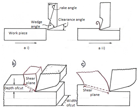
A planer is shown in Fig. In a side view, relative to feed direction, before the tool and workpiece are engaged. The rake and clearance angles are two of the most significant variables to consider in chip production; note that the wedge angle formed is a direct link between these two angles; that is, the bigger the total of clearance and rake angle, the smaller the wedge angle.
The clearance angle ensures that just the tool's cutting edge makes contact with the workpiece, and that the tool's rear, or heel, does not rub against the finished surface, deteriorating the finish and requiring more power.
The lower the wedge angle, the weaker and less able to disperse heat is the tip of the tool, as shown in. As a result, the ‘perfect' rake and clearance angles for a given material are frequently a compromise between outright cutting ability and acceptable strength.
Different sorts of chips can form under various cutting conditions, such as varied depths of cut, workpiece material, rake angles, cutting speed, and machine rigidity. Continuous and discontinuous chips are the two primary types of chips.
1.3.2 Types of Chip
- Discontinuous Chips
This sort of chip is commonly created while cutting hard, brittle materials, partially because these materials are unable to endure large shear forces, causing the chips to tear cleanly away. The chips formed, on the other hand, may be firmly or loosely linked to one another, or they may leave the cutting area in a fine shower, as is common when cutting hard Brass. When discontinuous chips are formed there is a greater possibility of tool chatter; unless the tool, tool-holder and workpiece are held very rigidly; due to pressure at the tool tip increasing during chip formation and then releasing suddenly as the chip shears see.
Advantages
In fragile materials, the development of discontinuous forms of chips gives a superior surface polish, extends tool life, and reduces power usage.
Disadvantages
When discontinuous chips form in ductile materials, the workpiece has a poor surface quality and the tool experiences significant wear and tear.
2. Continuous chips
When cutting soft or ductile materials like aluminium or copper, this type of chip is common. When discontinuous chips are created, there is less chance of chatter, and the surface smoothness is usually superior. Continuous chips have the problem of becoming very lengthy and becoming entangled with the machine or posing a safety issue. This problem can be overcome by the use of chip-breakers; a device clamped to the top of the tool that encourages the chip to curl more tightly, hitting the work piece and breaking off.
Advantages:
The advantages of forming continuous chips during the machining process are as follows:
- The ductile material has a better surface polish.
- Because there is less friction between the tool face and the chip, less heat is generated.
- Power usage is low.
- Due to fewer wear and tear, the tool has a longer life span.
3. Built Up Edge
Shown below is a tool with a Built Up
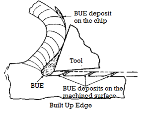
Edge (B.U.E.).
It is formed when During cutting, particles of the workpiece material weld to the tool's rake face. Large B.U.E.s can degrade surface polish and integrity by changing the geometry of the cutting edge and, as a result, the shear plane angle, which can cause residual stresses in the material below the depth of cut. When a large B.U.E. Dislodges, work hardened particles can be deposited and embedded in the completed surface.
A thin, stable B.U.E. Is often preferred since it can help to prevent frictional wear on the tool's rake face.
TOOL WEAR
Cutting tools with a wedge form usually wear in two ways. The typical wear pattern of a wedge shape cutting tool is shown in Figure.
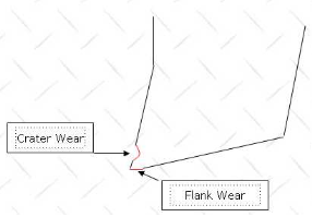
The rubbing of the chip across the surface causes crater wear on the rake face of the tool directly behind the cutting edge. Flank wear occurs on the tool's clearance angle, generating rubbing and surface finish degradation.
When flank wear exceeds 0.25mm or cratering emerges, cutting tools are regarded to have failed and require regrinding or replacement; this facilitates regrinding with minimal tool material removal. As seen in Fig, when cratering occurs, the cutting edge thins and becomes less able to dissipate the heat generated during cutting, resulting in unpredictable and potentially catastrophic failure. The three stages of tool wear are depicted in Figure i) initial rapid wear, ii) uniform wear, and iii) terminal wear – failure.
1.3.3 CHIP FORMATION IN TURNINGWhen the underlying idea of chip generation is applied to the simple example of planning, the similarities between the two become obvious.
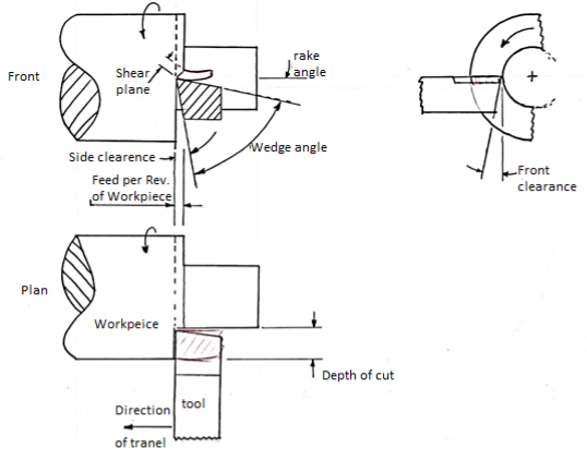
The tool is fed along the workpiece at a constant rate (F) as the workpiece rotates, taking an even thickness cut and creating chips in the same manner. Spindle speed and feed rate are calculated using formulas.
1.3.4 Chip Breaker
• A continuous type chip from a lengthy cut is usually a pain to remove from the swarf tray because it fouls the tools, clutters the machine, and causes a mess in the workplace.
•Chip breakers are used to reduce the swarf into little bits as they are generated, making it easier to handle and preventing it from becoming a workplace danger.
• The chip breaker performs better because the metal has previously been work hardened.
• Chip breakers come in a variety of shapes and sizes, but they all have a step or groove ground into the tool's leading edge or a piece of cutting tool material fastened on top.
The following are the most popular methods of breaking the chips in everyday shop practise:
- By clamping a piece of sheet metal over the coil's route.
- With a stepped type breaker, a step is ground into the tool's face along the cutting edge.
- Using a groove type breaker, which grinds a little groove below the cutting edge.
- With a clamp breaker, a thin carbide plate or clamp is brazed or fastened onto the tool's face.
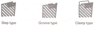
1.3.5 Mechanism of Chip formation:
• The workpiece travels to the right while the tool remains stationary. In the area directly in front of the cutting tool, the metal is strongly crushed.
• If the metal is ductile, this results in high temperature shear and plastic flow.
• When the stress in the workpiece just ahead of the cutting tool exceeds the metal's ultimate strength, particles shear and create a chip element that moves up the workpiece's face.
• Work hardening stops each succeeding element's outward or shearing action, and the movement is transferred to the next element.
• As a result of the shearing action, a continuous chip with a strongly compressed and burnished underside and a minutely serrated top side is generated.
• The shear plane is the plane along which the element shears.
• As a result, the chip is created by plastic deformation of the metal grain structure along the shear line.
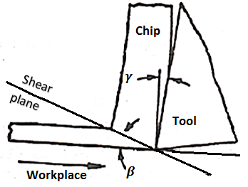
1.4.1 Assumptions for Merchant's circle diagram
The following are the assumptions for the merchant circle diagram.
• The cutting tool must be sharp, and the cutting tool must not come into touch with the clearance edge.
• There is no built-up edge and the chip production is continuous.
• The uncut chip's thickness remains unchanged.
• During the cutting operation, the workpiece moves at a constant speed.
• The workpiece's width is always less than the cutting tool's width.
• Shear occurs in a shear plane with homogenous stress distribution.
1.4.2 Merchant's circle diagram
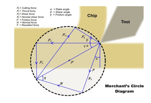
The merchant circle diagram shown above makes determining cutting force relations in metals simple.
1.4.3 Merchant's circle equation and derivation
The following force components are listed below, based on the aforementioned merchant circle diagram.
• The circle's diameter and the resulting force are denoted by F.
• Fz represents the cutting force.
• Fx represents the pushing force.
A dynamometer is used to analyse the cutting force and thrust force mentioned above. These forces are then analysed and plotted on a suitable scale.
The product of cutting force (Fz) and thrust force (Fx) equals force (F).
The following angles are denoted as follows in the diagram above.
Where,
α=Rake angle
β=Shear angle
γ=Friction angle
The normal force (N) and frictional force (P) act against the cutting tool, which is perpendicular to each other. The frictional force created along the tool rack face to oppose chip flow is known as the frictional force. As a result, the coefficient of friction between the tool and the chip may be calculated by multiplying these two forces together.
The coefficient of friction is denoted as μ.

The ratio of above two forces is also expressed in the form of trignometry relation.

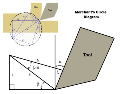
A part of Merchant's Circle Diagram
From the above diagram, the chip thickness ratio is denoted as r.

Where,


(t1 and t2 are thickness of chip before and after cutting)
Therefore,


We know that,

Therefore,


By dividing equation (5) by sinβ


Therefore, the value of tanβt is,

From the merchant diagram we know that,
P=Friction force
P=Fxcosα+Fzsinα
N=Normalforce
N=Fzcosα+Fxsinα
F=Resultant force
F=
 =Cuttingforce
Fz=Fcos(γ−α)
Fs=Shear force
Fs=Fcosθ
Where, θ=β+γ−α

Substitute (7) in Fz equation,


From (1) and (2),

And the coefficient of friction,

By trigonometric relations, the value of Fs and Fn is obtained from the merchant circle diagram.


And,


In some special cases, when rake angle is zero (α=0), then F and N becomes,
F=Fx
N=Fz
A dynamometer is used directly to measure cutting force and its thrust force in this special case.
1.4.4 How to draw Merchant’s circle diagram?
Consider the state of an orthogonal cutting process with the specified feed, tool geometry, and cut depth. We only have the values of two forces (Fx and Fz) that are measured with a dynamometer now. We'll derive the other force relations quickly and easily using the merchant's circle diagram and associated equations.
• Calculate the value of Fx, the thrust force.
• Draw the chip and tool on the orthogonal plane, knowing the tool's rake angle.
• Draw the horizontal component of force Fz and the vertical component of force Fx.
• Fx and Fz's resultant force F is drawn for the forces. A formula is used to calculate the value of the resulting force FF.

• Draw a circle around the midpoint of the resultant force F.
• Extend the tool's rake surface by extending a line along with it and mark it as friction force P.
• Create a normal force N that is perpendicular to the friction force P. A formula is used to calculate the friction coefficient.
μ=PN
• Using a shear angle, draw the shear plane.
• The value of the shear angle is calculated using a formula that has already been developed.

Draw Fs and Fn as intercepts.
1.4.5 Advantages of Merchant's circle diagram
The following are the benefits of the merchant's circle diagram:
• MCD is simple to use and understand.
• Other force connections are simple to resolve.
• Friction at the tool surface and yield shear strength can both be easily evaluated using MCD.
1.4.6 Limitations of Merchant's circle diagram
Merchant's circle diagram has certain drawbacks as well.
• The merchant's circle diagram is not employed except for orthogonal cutting since it is based on a single shear plane principle. • The friction coefficient obtained by the formula derived from MCD is merely an approximate number.
1.4.7 Numericals
Problem 1 γ0 = 100, it was found PZ= 1000 N, ζ During turning a ductile alloy by a tool of Px= 400 N, Py= 300 N and = 2.5. Evaluate, using MCD, the values of F, N and μ as well as Ps and Pn for the above machining.
Solution:
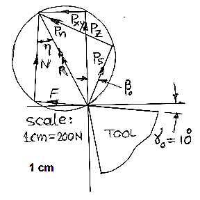
Force, 
Select a scale: 1 cm=200N
Draw the tool tip with γ0 =100
In scale, PZ=1000/200= 5 cm and Pxy=500/200=2.5cm
Draw PZ and PXY in the diagram
Draw R and then the MCD
Extend the rake surface and have F and N as shown
Determine shear angle, βo


Draw Ps and Pn in the MCD
From the MCD, find F = 3x200 = 600 N; N = 4.6x200 = 920 N;
μ = F/N = 600/920 = 0.67
Ps = 3.4x200 = 680; Pn= 4.3x200 = 860 N.
Problem 2
A ceramic insert of geometry was used to cut a steel rod with a diameter of 160 mm at a speed of 560 rpm, feed of 0.32 mm/rev, and a depth of cut of 4.0 mm during turning.
00, —100, 60, 60, 150, 750, 0 (mm)
The followings were observed: PZ =1600 N, PX=800 N and chip thickness=1mm MCD the possible values of F, N, mA , PS , PN , cutting power and specific energy consumption.
Solution:

- Select a scale: 1cm = 400N
- Draw the tool tip with γ = -100
- Draw PZ and PXY in scale as shown
- Draw resultant and MCD
Shear angle, β0

Where 

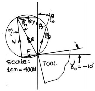
● Draw Ps and Pn as shown
● Using the scale and intercepts determine
F = 1.75xscale = 700 N
N = 4.40xscale = 1760 N
ma = F/N = 700/1760 = 0.43
Ps = 3.0 x scale = 1200 N
Pn= 3.3 x scale = 1320 N
● Cutting Power, Pc Pc= Pz.Vc where
Vc = πDN/1000 = π x160x560/1000 = 281.5 m/min
So, PC = 8 KW.
● Specific energy = Pz/(tso) = 1600/(4 x 0.32)= 1250 N-mm/mm3
1.5.1 Different Types of Cutting Tools Materials and Their Properties
There are numerous distinct sorts of cutting processes that are used in various situations. They require some particular features under such circumstances, in addition to the normal needs of the cutting instrument. Cutting tools are built of various materials to attain these qualities. The material selected for a given application is determined by the material to be machined, the type of machining, the quantity, and the quality of the finished product.
The tools are divided into categories based on the material they are made of.
- Carbon tool steel
- High speed steel tool (HSS)
- Cemented carbide
- Ceramics tool
- Cubic boron nitride Tool (CBN)
- Diamond tool
1.5.2 Introduction
When planning a successful metal cutting operation, selecting the right cutting tool material and grade is critical.
When choosing the right choice, it's necessary to have a fundamental understanding of each cutting tool's material and performance. The workpiece material to be machined, the component type and shape, the machining circumstances, and the level of surface quality required for each operation are all factors to consider.
This section explains the different types of cutting tools, their benefits, and how to use them properly.
Cutting tool materials come in a variety of hardness, toughness, and wear resistance combinations, and are classified into a number of grades with various qualities. In general, a cutting tool material that is effective in its use should be:
• Tough, to resist wear and distortion on the flanks
• Tough enough to withstand mass breakage
• Non-reactive with the material of the workpiece
• Chemically stable, so it won't oxidise or diffuse.
• Resistant to extreme temperature changes
1.5.3 Coated cemented carbide cutting tool material
● Coating – CVD
● Coating – PVD
● Cemented carbide
What is coated cemented carbide cutting tool material?
Currently, coated cemented carbide accounts for 80-90 percent of all cutting tool inserts. Its popularity as a cutting tool material stem from its unique mix of wear resistance and hardness, as well as its ability to produce complicated shapes.
Cemented carbide with a coating is known as coated cemented carbide. They combine to generate a grade that is tailored to its intended use.
For a wide range of tools and applications, coated cemented carbide grades are the first choice.
Coating – CVD
Definition and properties
Chemical Vapor Deposition (CVD) is an acronym for Chemical Vapor Deposition. Chemical reactions at temperatures ranging from 700 to 1050°C produce the CVD coating.
CVD coatings provide great adherence to cemented carbide and have a high wear resistance.
The single layer titanium carbide coating was the first CVD coated cemented carbide (TiC). Later on, alumina (Al2O3) and titanium nitride (TiN) coatings were developed. Modern titanium carbonitride coatings (MT-Ti(C,N) or MT-TiCN, also known as MT-CVD) were created more recently to increase grade qualities by keeping the cemented carbide interface intact.
MT-Ti(C,N), Al2O3, and TiN are all used in modern CVD coatings. Through microstructural optimizations and post-treatments, the coating qualities for adhesion, toughness, and wear have been constantly improved.
MT-Ti(C,N) - Its hardness makes it resistant to abrasive wear, resulting in less flank wear.
CVD-Al2O3 is chemically inert and has a low thermal conductivity, making it crater-resistant. It also serves as a thermal barrier to help prevent plastic deformation.
CVD-TiN - Increases wear resistance and can be used to monitor wear.
Post-treatments improve edge hardness and prevent smearing in interrupted cuts.
Applications
In a wide range of applications where wear resistance is critical, CVD coated grades are the first choice. General turning and boring of steel, with crater wear resistance provided by thick CVD coatings; general turning of stainless steels, and milling grades in ISO P, ISO M, and ISO K are examples of such uses. CVD grades are commonly utilised in the periphery insert for drilling.
Coating – PVD
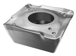
Definition and properties
PVD coatings (Physical Vapor Deposition) are created at low temperatures (400-600°C). The method entails the evaporation of a metal, which then combines with nitrogen to generate a hard nitride coating on the cutting tool surface.
Due to its hardness, PVD coatings increase wear resistance to a grade. Edge toughness and comb crack resistance are also improved by their compressive stresses.
The key components of PVD coatings are listed below. These elements are combined in sequenced layers and/or lamellar coatings in modern coatings. Lamellar coatings have many thin layers in the nanoscale range, increasing the coating's hardness.
PVD-TiN - The first PVD coating was titanium nitride. It has a golden colour and all-around characteristics.
PVD-Ti(C,N) - Titanium carbonitride is tougher than TiN and adds resistance to flank wear.
PVD-(Ti,Al)N - Titanium aluminium nitride has a high hardness and oxidation resistance, resulting in improved overall wear resistance.
PVD-oxide is employed because of its chemical inertness and increased crater resistance.
Applications
For robust, yet sharp, cutting edges, as well as smearing materials, PVD coated grades are recommended. All solid end mills and drills, as well as the majority of grades for grooving, threading, and milling, are used in this way. PVD-coated grades are also commonly utilised in finishing applications and as the drilling's central insert grade.
Cemented carbide
Definition and properties
Cemented carbide is a powdery metallurgical material that is made up of tungsten carbide (WC) particles and a cobalt-rich binder (Co). More than 80% of hard phase WC is present in cemented carbides for metal cutting applications. Other essential components, particularly in gradient sintered grades, include additional cubic carbonitrides. The cemented carbide body is sintered to full density after being shaped into a body using powder pressing or injection moulding techniques.
The finer the grain size, the higher the hardness at a given binder phase content; the finer the grain size, the greater the hardness at a given binder phase content.
The toughness and resistance to plastic deformation of the grade are controlled by the amount and content of the Co-rich binder. At the same WC grain size, adding more binder results in a harder grade that is more susceptible to plastic deformation wear. A brittle material can be caused by a low binder content.
Cubic carbonitrides, also known as -phase, are commonly used to boost hot hardness and create gradients.
To combine better plastic deformation resistance with edge toughness, gradients are used. Cubic carbonitrides concentrated on the cutting edge enhance hot hardness where it is required. A binder rich in tungsten carbide structure prevents cracks and chip hammering fractures beyond the cutting edge.
Applications
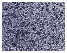
WC grain size ranges from medium to coarse.
Cemented carbides with medium to coarse WC particle sizes have an excellent combination of high hot hardness and toughness. These are utilised in grades for all regions in conjunction with CVD or PVD coatings.

WC particle size is fine or submicron.
Sharp cutting edges are made with fine or submicron WC grain sizes and a PVD coating to increase the sharp edge's strength. They have a higher resilience to thermal and mechanical cyclic stresses as well. Solid carbide drills, solid carbide end mills, splitting off and grooving inserts, milling, and finishing grades are all common applications.
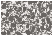
Carbide cemented with a gradient
In many first-choice grades for turning, splitting, and grooving in steels and stainless steels, the favourable dual feature of gradients is successfully combined with CVD coatings.
1.5.4 Uncoated cemented carbide cutting tool material
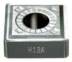
What is uncoated cemented carbide cutting tool material?
Uncoated cemented carbide grades make just a tiny percentage of the total cutting tool selection. These grades are either straight WC/Co or have a high volume of cubic carbonitrides.
Applications
Machining HRSA (heat resistant super alloys) or titanium alloys, as well as turning hardened materials at moderate speeds, are common uses for this cutting tool material.
Uncoated cemented carbide grades have a fast yet controlled wear rate and a self-sharpening action.
1.5.5 Cermet cutting tool material
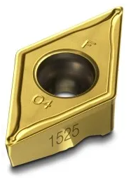
What is cermet cutting tool material?
Cermet is a titanium-based cemented carbide with hard particles. Cermet is a combination of the words ceramic and metal. Cermet was originally made up of TiC and nickel. Modern cermets have a specified structure of titanium carbonitride Ti(C,N) core particles, a second hard phase of (Ti,Nb,W)(C,N), and a W-rich cobalt binder, and are nickel-free.
Wear resistance is added by Ti(C,N), plastic deformation resistance is increased by the second hard phase, and toughness is controlled by the amount of cobalt.
Cermet outperforms cemented carbide in terms of wear resistance and smearing resistance. On the other side, it has a lower compressive strength and is less resistant to thermal shock. PVD coatings can also be applied on Cermets to improve wear resistance.
Applications
Cermet grades are utilised in smearing situations when there is a difficulty with a built-up edge. Even after long times in the cut, its self-sharpening wear pattern keeps cutting forces low. This allows for a long tool life and tight tolerances in finishing operations, as well as bright surfaces.
Stainless steel finishing, nodular cast iron finishing, low carbon steel finishing, and ferritic steel finishing are all common applications. Cermets can be used to troubleshoot problems in any ferrous material.
Hints:
• Use a low feed rate and a shallow cut depth.
• When flank wear reaches 0.3 mm, change the insert edge.
• By machining without coolant, you can avoid thermal cracks and fractures.
1.5.6 Ceramic cutting tool material
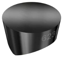
What is ceramic cutting tool material?
At high cutting speeds, all ceramic cutting tools have good wear resistance.
A number of ceramic grades are offered for various uses.
Oxide ceramics are made of aluminium oxide (Al2O3) with zirconia (ZrO2) added for crack resistance. This results in a material that is chemically very stable but not thermally shock resistant.
(1) Cubic carbides or carbonitrides (TiC, Ti(C,N)) are used to particle-reinforce mixed ceramics. Toughness and thermal conductivity are improved as a result.
(2) Silicon carbide whiskers (SiCw) are used to greatly increase toughness and permit the use of coolant in whisker-reinforced ceramics. For machining Ni-based alloys, whisker-reinforced ceramics are excellent.
(3) Another type of ceramic material is silicon nitride ceramics (Si3N4). Their elongated crystals form a self-reinforced, high-toughness material. Silicon nitride grades function well in grey cast iron, but their chemical stability prevents them from being used in other materials.
Sialon (SiAlON) grades combine the strength and chemical stability of a self-reinforced silicon nitride network. Sialon grades are good for machining super alloys that are heat resistant (HRSA).

Applications
Ceramic grades can be used in a wide range of applications and materials, with the most common application being high-speed turning, but they can also be used in grooving and milling. When used correctly, the unique qualities of each ceramic grade enable high production. It's crucial to understand when and how to employ ceramic grades if you want to be successful.
Ceramics' thermal shock resistance and fracture toughness are two of their most common drawbacks.
1.5.7 Polycrystalline cubic boron nitride cutting tool material
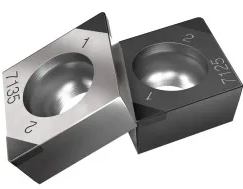
What is polycrystalline cubic boron nitride cutting tool material?
Polycrystalline cubic boron nitride, CBN, is a cutting tool material with excellent hot hardness that can be used at very high cutting speeds. It also has a high level of hardness and resilience to thermal shock.
Ceramic composites with a CBN composition of 40-65 percent make up modern CBN grades. The CBN, which is otherwise prone to chemical wear, gains wear resistance thanks to the ceramic binder. The high content CBN grades, which range from 85 percent to nearly 100 percent CBN, are another group of grades. A metallic binder may be used to improve the toughness of these grades.
To make an insert, CBN is brazed onto a cemented carbide carrier. The Safe-LokTM technology improves the bonding of CBN cutting tips to negative inserts even more.
Applications
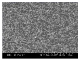
CBN grades are commonly used to complete turn hardened steels with hardnesses more than 45 HRc. CBN is the only cutting tool that can replace traditional grinding processes over 55 HRc. Steels of a lower hardness, below 45 HRc, have more ferrite, which reduces the wear resistance of CBN.
In both turning and milling processes, CBN can be utilised for high-speed roughing of grey cast irons.
1.5.8 Polycrystalline diamond cutting tool material
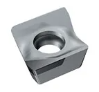
What is polycrystalline diamond cutting tool material?
PCD is a diamond-particle composite with a metallic binder that is sintered together. Diamond is the hardest of all materials, and thus the most abrasion resistant. It has good wear resistance as a cutting tool material, but it lacks chemical stability at high temperatures and dissolves rapidly in iron.
Applications
PCD can only be used on non-ferrous materials like high-silicon aluminium, metal matrix composites (MMC), and carbon fibre reinforced polymers (CFRP). Titanium super-finishing can also benefit from PCD with flood coolant.
1.5.9 Some more types:
1. Steels made of carbon
Carbon steels have been utilised for cutting tools since the 1880s. Carbon steels, on the other hand, begin to soften at around 180°C. Because of this constraint, such tools are rarely employed in metal cutting operations. Plain carbon steel tools, hardened to about 62 Rc and having about 0.9 percent carbon and around 1% manganese, are commonly used in woodworking and may be used in a router to machine aluminium sheet up to about 3mm thick.
2. High-strength steel (HSS)
HSS tools get their name from the fact that they were designed to cut at high rates. HSS tool steels, which were developed around 1900, are the most heavily alloyed tool steels. Tungsten (T series) was the first to be developed, and it normally contains 12 to 18 percent tungsten, along with around 4% chromium and 1 to 5% vanadium. The majority of grades contain about 0.5 percent molybdenum and 4 to 12 percent cobalt.
Soon after, it was discovered that molybdenum (in lesser quantities) could be used to replace most of the tungsten, resulting in a more cost-effective formulation with superior abrasion resistance and less deformation after heat treatment than the T series. As a result, M series grades account for almost 95% of all HSS tools. These contain 5 to 10% molybdenum, 1.5 to 10% tungsten, 1 to 4% vanadium, 4% chromium, and many grades have 5 to 10% cobalt.
HSS tools are used to make complex-shaped tools such as drills, reamers, taps, dies, and gear cutters because they are robust and appropriate for interrupted cutting. Coatings can also be applied to tools to increase their wear resistance. The largest tonnage of tool materials now in use is HSS. Cutting speeds range from 10 to 60 metres per minute.
3. Cobalt Alloys (Cast)
These alloys, which were first introduced in the early 1900s, have a cobalt content of 40 to 55 percent, a chromium content of 30 percent, and a tungsten content of 10 to 20 percent. They are not heat treatable. Rc values of 55 to 64 are the maximum hardness levels. They have good wear resistance but aren't as robust as HSS, although they can be utilised at greater speeds. Only a few people know about it now.
4. Carbides
Introduced in the 1930s, cemented carbides and sintered carbides offer high hardness over a wide temperature range, good thermal conductivity, and high Young's modulus, making them useful tool and die materials for a variety of applications.
Tungsten carbide and titanium carbide are the two forms of carbides used for machining, and both can be coated or uncoated.
Powder metallurgy is used to link tungsten carbide particles (1 to 5 microns) together in a cobalt matrix. The powder is sintered into the necessary insert shape after being pressed. To give unique qualities, titanium and niobium carbides may be used.
For various uses, a variety of grades are available.
In metal cutting, sintered carbide tips are the most used material.
The amount of cobalt (the most common matrix material) in carbide tools has a considerable impact on their qualities. Hardness increases with a cobalt matrix of 3 to 6%, whereas toughness increases with a cobalt matrix of 6 to 15%, while hardness, wear resistance, and strength decrease. Steels, cast irons, and abrasive non-ferrous materials are routinely machined with tungsten carbide tools.
Titanium carbide is more resistant to wear than tungsten, but it is not as robust. TiC is ideal for machining at faster speeds than tungsten carbide because it has a nickel-molybdenum alloy as the matrix. Cutting rates range from 30 to 150 m/min, or 100 to 250 m/min when coated.
5. Different Coatings
Coatings are often added to carbide tool tips to extend their life or permit faster cutting speeds. Coated tips have a 10-fold longer lifespan than untreated tips. Titanium nitride, titanium carbide, and aluminium oxide are common coating materials, with thicknesses ranging from 2 to 15 micrometres. Depending on the intended application of the tip, numerous layers may be applied, one on top of the other. Coatings are applied using chemical vapour deposition (CVD), plasma assisted CVD, and physical vapour deposition processes (PVD).
Diamond coatings are also used and are being explored further.
6. Cermets
These were developed in the 1960s and typically contain 70% aluminium oxide and 30% titanium carbide. Molybdenum carbide, niobium carbide, and tantalum carbide are all used in some formulations. Their performance is comparable to that of carbides and ceramics, and coatings appear to provide minor advantages. Cutting speeds range from 150 to 350 m/min.
7. Alumina
Two kinds of cutting tools were introduced in the early 1950s: fine-grained high purity aluminium oxide (Al2O3) and silicon nitride (Si3N4), which were pressed into insert tip shapes and sintered at high temperatures. To improve characteristics, titanium carbide and zirconium oxide (ZrO2) can be added. However, whereas ZrO2 increases fracture toughness, it decreases hardness and heat conductivity. To improve toughness and thermal shock resistance, silicon carbide (SiC) whiskers can be added.
The tips' strong abrasion resistance and hot hardness, as well as their greater chemical stability compared to HSS and carbides, imply they're less prone to attach to metals during cutting and, as a result, have a decreased inclination to produce a built-up edge. Their principal flaw is low toughness, which necessitates the use of negative rake angles to minimise chipping due to their low tensile strengths. When machining with ceramic tips, use stiff machine tools and work setups; otherwise, vibration will cause the tip to fail prematurely. Cutting speeds range from 150 to 650 m/min.
8. Silicon Nitride
In the 1970s, silicon nitride-based tool materials were created, which may also include aluminium oxide, yttrium oxide, and titanium carbide. SiN is attracted to iron and is hence unsuitable for machining steels. 'Sialon' is a specific kind that contains the elements silicon, aluminium, oxygen, and nitrogen. It is recommended for machining cast irons and nickel-based superalloys at moderate cutting rates because it has a stronger thermal shock resilience than silicon nitride.
Boron Nitride in Cubic (cBN)
This substance, which was first introduced in the early 1960s, is the second hardest after diamond. Small solid tips or a 0.5 to 1 mm thick coating of polycrystalline boron nitride sintered onto a carbide substrate under pressure are both options for cBN tools. The carbide layer provides shock resistance in this example, while the cBN layer gives extremely high wear resistance and cutting edge strength. For machining alloy and tool steels with a hardness of 50 Rc or above, cubic boron nitride is the industry standard. Cutting speeds range from 30 to 310 m/min.
9. Diamond
Diamond is the hardest substance known to man. Although single crystal diamonds have been used as tools, they are fragile and must be mounted with the precise crystal orientation in order to have the best tool life. Polycrystalline diamond has mostly superseded single crystal diamond tools (PCD). This is made up of very minute synthetic crystals fused to a carbide substrate using a high temperature high pressure technique to a thickness of between 0.5 and 1mm. The end effect resembles that of cBN tools. The diamond crystals' irregular orientation minimises crack development, increasing hardness.
PCD is not appropriate for machining plain carbon steels, nickel, titanium, or cobalt-based alloys due to its reactivity.
PCD is best suited to light, continuous finishing cuts at nearly any speed, and is primarily used for machining non-metallic materials such as aluminum-silicon alloys, composites, and other non-metallic materials at very high speeds. Cutting speeds range from 200 to 2000 m/min. Ten additional materials
Tools with whisker reinforcement, such as silicon nitride reinforced with silicon carbide whiskers, are being developed to improve tool toughness.
Curves of Tool Life
The Taylor tool life equation is expressed as v(T)n = C, where n is the number of tools.
v represents the cutting speed in m/min, T represents the tool life in minutes, C represents the cutting speed for a one-minute tool life, and n represents the Taylor exponent (Do not confuse this use of n with the cold working index n).
Tool Material | Typical 'n' value |
High-speed steels | 0.08 - 0.2 |
Cast Alloys | 0.1 - 0.15 |
Carbides | 0.2 - 0.5 |
Ceramics | 0.5 - 0.7 |
Key takeaways:
• When picking the right choice, it's necessary to have a fundamental understanding of each cutting tool's material and performance. The workpiece material to be machined, the component type and shape, the machining circumstances, and the level of surface quality required for each operation are all factors to consider.
• Cemented carbide is a hard substance that is widely utilised in cutting tools and other industrial applications. It is made up of tiny carbide particles bonded together by a binder metal.
• Diamond the toughest material known, however it can only withstand temperatures of 600°C and cannot be used to manufacture steel.
1.6.1 Introduction:
In the machining process, tool wear is an unavoidable cause of tool failure. The amount of tool wear has a significant impact on the dimensional accuracy and surface polish that can be achieved. A cutting tool's gradual wear happens in three main regions. Cutting tool wear is divided into three categories based on this classification.
- Flank wear
- Crater wear
- Corner wear
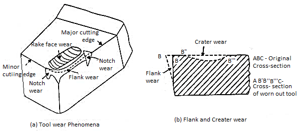
Flank wear
Work hardening is to blame. Abrasion and adhesion wear cause flank wear at the tool's flanks, where it comes into contact with the finished surface. With flank wear, the cutting force increases. It has a significant impact on cutting mechanics. The breadth of wear land is used to measure the width of the flank wear region. Excessive cutting pressures induce tool failure when the wear land width exceeds 0.5-0.6mm.
Crater wear
Chip flow over the tool face at a high temperature causes crater wear on the tool face at a short distance from the cutting edge. Diffusion and abrasion are the main causes of crater wear. They are frequently seen in areas where a continuous chip is created (usually in the ductile material). When a chip is formed in the shape of a short segment in brittle material, this loosely fragmented chip has less abrasive impact on the face than a continuous chip creation. The crater wear is measured by the depth of the crater, which can be measured using a surface measuring tool. Due to excessive cratering, the cutting edge of the tool may shatter.
1.6.2 Tool Wear Mechanism – Abrasion, Adhesion, Diffusion, Fatigue and Oxidation Wear.
It is necessary to understand the limitations and applications of tool material in order to comprehend the many wear mechanisms that a cutting tool is subjected to.
Abrasion wear
This is the most typical wear mechanism. When a hard particle on a chip travels over the cutting tool face, abrasion occurs. In steel alloys, it is caused by oxides, nitrides and other nonmetallic inclusion present in the workpiece. This hard inclusion having sharp edges comes in contact with a cutting tool and removes material from the tool surface by abrasion action. This wear pattern is more consistent, resulting in a longer tool life.
Adhesion wear or attrition wear
Chip material ripped off the small piece from the tool, causing adhesion wear. The tool-chip interface generates a metallic bond in the form of spot welds at high temperature and pressure at the cutting edge. A spot weld causes an erratic flow of chips across the tool face, resulting in built-up edges. The fracture of this minor weld joint, as well as some tool material, is caused by the chip sliding over the built-up, a phenomenon called as adhesion. Cutting fluids that form a protective coating on the contact surface can help prevent adhesive wear.
Diffusion wear
Diffusion wear occurs when atoms in a crystal lattice shift from an area of high concentration to a region of low concentration (Ficks law). The surface structure of a cutting tool is weakened by diffusion, which leads to tool failure. Localized temperature at the tool-chip interface provides a suitable environment for diffusion.
Temperature affects the amount of diffusion.
The solubility of tool material in work material, as well as the binding affinity of tool and chip materials.
Contact time between the tool and the chip.
Fatigue wear
When two surfaces glide in touch with each other under high pressure, it occurs at the microscopic level. On one rough surface, a hill interlocks with those on another. As it slips over another slope, it produces cyclic stress. A surface that is exposed to fatigue wear due to frequent loading and unloading. When other wear rates are really low, it only comes to measure. Surface cracks are caused by fatigue wear, which eventually merge and lead to surface crumble. Another cause of fatigue wear is cyclic thermal stress.
Oxidation wear (corrosive wear)
Oxidation develops a layer of oxides on the tool surface as a result of a chemical interaction between the tool surface and oxygen at high temperatures. When this layer is abrasion-destroyed during the cutting process, a new layer forms. As this removal and development of the corrosive layer is repeated, tool wear occurs.
Edge chipping (premature wear)
Breaking away of small chips from cutting edge of the tool due to interrupted cutting and sudden shock. When cutting with a variable depth of cut, this happens.
1.6.3 Tool wear depends upon following parameters:
i. Tool and work piece material.
Ii. Tool shape.
Iii. Cutting Speed.
Iv. Feed.
v. Depth of cut.
Vi. Cutting fluid used.
Vii. Machine Tool characteristics etc.
1.6.4 Tool wear affects following items:
i. Increased cutting forces.
Ii. Increased cutting temperature.
Iii. Decreased accuracy of produced parts.
Iv. Decreased tool life.
v. Poor surface finish.
Vi. Economics of cutting operations.
1.6.5 Measuring Tool Wear
During a tool trial or a machine set-up evaluation, how do you know when you've reached the best conditions?
The method outlined here will cut down on trial time while also improving the accuracy of your results.
It takes time to perform an extended trial that incrementally pushes greater piece counts or faster cycle durations, whether you're assessing a new cutting tool, a cutting fluid, or setting up the oil/air ratio for Minimum Quantity Lubrication (MQL) applications.
It is critical that the machine is in a stable state before any MQL or coolant trial may take place. The MQL or the cutting fluid will not be able to eliminate chatter. Different tool geometry, on the other hand, can reduce chatter in specific instances.
Other aberrant wear patterns should be recognised before starting, aside from chatter, which appears soon. Flank or Land wear is the only wear pattern that demonstrates a stable machining process.
A trial is frequently staged with a shaky baseline or with few process pieces in a known or fixed condition. When comparing end outcomes, for example, tool edge preparation is crucial, especially if the tool is coated. Before being installed, each tool utilised in the trial should be certified.
Example 1
If you were a coolant supplier and this new tool showed up during your coolant trial, there's a good chance your coolant would have "failed."
The findings of a MQL examination will be misleading if this instrument has a fault.
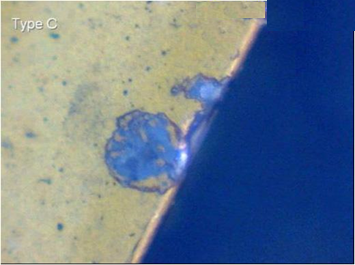
Example 2
This new tool's covering contains problems in the land area.

Example 3
The wear pattern was accelerated during the machining trial, and the coolant was deemed a "failure." Despite the new tool, the coolant was not examined under controlled settings.

The work piece blank size and metallurgical variance are two further variables to be regulated during a trial. If the dimensions of the arriving blanks fluctuate, the extra cubic centimetres of material that have to be removed will lower tool life if the piece count is used. Batches of incoming blanks are frequently skewed to either a higher or lower machined dimension.
Even if the chemistry is right, a minor variation in the metallic structure will alter chip formation and result in differing tool pressures. Even a two-point increase in Rockwell hardness will increase the tool's pressure. This is enough to shorten the tool's lifespan.
The second set of conditions (V115) produced the least amount of wear among the three settings in this assessment. Only three tools were employed in this experiment. Each tool was capable of producing 15,000 components.
The second set of conditions reflects a tool life increase of around 100%. If a shorter cycle time is desired, increasing the cutting speed is a reasonable alternative, especially since this lubricant or lubricant condition resulted in a significant reduction in tool wear.
Excessive wear was seen in both the V1 and V25 situations. The V15 conditions are clearly favourable to greater tool wear, based on these findings.
This method of measurement has been used to evaluate tools, tool coatings, coolants, and MQL. This approach had a measuring error of around 0.003 mm2.
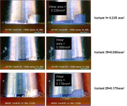
1.7.1 Basic methods of controlling cutting temperature
Cutting temperature, especially when it is relatively high, is known to be exceedingly harmful to both cutting tools and machined items, and thus must be regulated, i.e. reduced as much as possible without sacrificing productivity and product quality.
The following are some of the most common strategies for reducing machining temperature and its negative effects: • Proper tool selection; material and geometry
• Choosing the right cutting speed and feed
• Proper cutting fluid selection and application
- Selection of material and geometry of cutting tool for reducing cutting temperature and its effects
Depending on the work material, the cutting tool material may play a considerable influence in lowering the cutting temperature. For example, by reducing friction at the chip-tool and work-tool interfaces, PVD or CVD coating of HSS and carbide tools can lower cutting temperatures.
- In high speed machining of steels lesser heat and cutting temperature develop if machined by cBN tools which produce lesser cutting forces by retaining its sharp geometry for its extreme hardness and high chemical stability.
- If the thermal conductivity of ceramic tools is increased, the cutting tool temperature drops even further (by adding thermally conductive materials like metals, carbides, etc in Al2O3 or Si3N4) Cutting temperature can be adjusted in a significant way by selecting the right tool shape in the following ways:
- A large positive tool–rake reduces heat and temperature generation by reducing cutting forces, but an excessive increase in rake weakens the cutting edges mechanically and thermally.
- A compound rake, preferably with a chip–breaker, reduces heat and temperature by lowering cutting forces and friction.
- even for same amount of heat generation, the cutting temperature decreases with the decrease in the principal cutting edge angle, φ as
θαC [VC0.5(so sinφ)0.25 ]
- nose radiusing of single point tools not only improves surface finish but also helps in reducing cutting temperature to some extent.
2. Selection of cutting velocity and feed
Cutting temperature can also be regulated to some amount, even without sacrificing MRR, by choosing the right cutting velocity and feed within respective ranges. The quantity of cutting power consumed, PC, determines the rate of heat generation and thus the cutting temperature.
PC = PZ.VC = tsoτsfVC
As a result, increasing both so and VC appears to increase heat generation proportionally. But increase in VC, though further enhances heat generation by faster rubbing action, substantially reduces cutting forces, hence heat generation by reducing τs and also the form factor f. Other machining variables will influence the overall relative impacts of VC and so on cutting temperature. As a result, depending on the scenario, an optimal combination of VC and so for a given MRR can greatly affect the cutting temperature.
3. Control of cutting temperature by application of cutting fluid
If used, cutting fluid reduces cutting temperature both directly by removing heat from the cutting zone and indirectly by reducing heat output by reducing cutting forces.
1.7.2 Purposes of application of cutting fluid in machining and grinding.
Cutting fluid application serves two fundamental purposes: • cooling of the job and tool to limit the negative impacts of cutting temperature on the job and tool; and • lubrication of the chip–tool interface and tool sides to reduce cutting forces and friction, and hence the amount of heat generated.
• Washing away chip – particles and debris from the machining zone, which, if present, degrades the finished surface and increases cutting edge deterioration.
• Protection of the nascent finished surface - a thin coating of cutting fluid adheres to the machined surface, preventing dangerous contamination by gases in the atmosphere such as SO2, O2, H2S, and NxOy.
However, the primary goal of using cutting fluid is to increase machinability by lowering cutting forces and temperatures, increasing surface integrity, and extending tool life.
1.7.3 Essential properties of cutting fluids
The cutting fluid should have the following attributes in order to fulfil its functional needs without hurting the Machine – Fixture – Tool – Work (M-F-T-W) system or the operators:
- For cooling:
- High specific heat, thermal conductivity and film coefficient for heat transfer
- Spreading and wetting ability
- For lubrication:
- High lubricity without gumming and foaming
- Wetting and spreading
- High film boiling point
- Friction reduction at extreme pressure (EP) and temperature
- Chemical stability, non-corrosive to M-F-T-W system materials
- Less volatile and high flash point
- High resistance to bacterial growth
- Odourless and preferably colourless
- Non-toxic in both liquid and gaseous states
- Readily available and inexpensive cost.
Principles of cutting fluid action
The chip-tool contact zone is usually comprised of two parts; plastic or bulk contact zone and elastic contact zone as indicated.
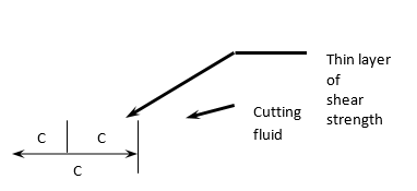
Cutting fluid action in machining
The cutting fluid cannot penetrate or reach the plastic contact zone, but by capillary effect, it enters the elastic contact zone. With the increase in cutting velocity, the fraction of plastic contact zone gradually increases and covers almost the entire chip-tool contact zone as indicated in Fig. As a result, when machining at high speeds, the cutting fluid becomes unable to lubricate and cools.
Apportionment of plastic and elastic contact zone with increase in cutting velocity.
Chemicals in the cutting fluid, such as chloride, phosphate, or sulphide, react chemically with the work material at the chip under surface under high pressure and temperature, forming a thin layer of the reaction result. The reaction layer's low shear strength aids in friction reduction.
A reasonable amount of extreme pressure additive (EPA) is purposely added to the mineral oil or soluble oil to generate such a solid lubricating layer under high pressure and temperature.
Depending on the operating temperature, chloride, phosphate, or sulphide type EPA is used for extreme pressure, i.e. moderate (200oC350oC), high (350oC500oC), and very high (500oC800oC).
Types of cutting fluids and their application
Cutting fluids are usually used in liquid form, but they can also be used in gaseous form. Solid lubricants are frequently used in machining and grinding for lubrication purposes only.
The following are some of the most widely utilised cutting fluids:
▪ Air blast or compressed air only.
Machining of some materials like grey cast iron become inconvenient or difficult if any cutting fluid is employed in liquid form. Only air blast is recommended for cooling and cleaning in this situation.
▪ Water
Water is the best coolant because of its good wetting and spreading qualities as well as its high specific heat. It is thus used where cooling is most needed.
▪ Soluble oil
Water is the most effective coolant, but it does not lubricate. Furthermore, using simply water may corrode the machine-fixture-tool-work system. As a result, an oil containing an emulsifying agent and an additive such as EPA, collectively known as cutting compound, is mixed with water in an appropriate ratio ( 1 2 in 20 50). Soluble oil, a milk-like white emulsion, is highly common and frequently used in machining and grinding.
▪ Cutting oils
Cutting oils are usually mineral oil mixtures to which various types and amounts of vegetable, animal, or marine oils are added to improve spreading, wetting, and lubricating qualities. In heavy cuts, some EP additive is mixed as needed to prevent friction, adhesion, and BUE generation.
▪ Chemical fluids
These are water-based cutting fluids in which some organic and inorganic components are dissolved in water to achieve the required cutting fluid activity.
Chemically inactive cutting fluids provide high cooling, anti-rusting, and wetting properties but are less lubricating.
Active (surface) kind - cooling and lubrication are mild.
▪ Solid or semi-solid lubricant
Paste, waxes, soaps, graphite, and Moly-disulphide (MoS2) are frequently used to minimise friction and hence cutting forces, temperature, and tool wear, either directly on the workpiece or as an impregnant in the tool.
▪ Cryogenic cutting fluid
In some exceptional instances, extremely cold (cryogenic) fluids (typically in the form of gases) such as liquid CO2 or N2 are utilised to provide effective cooling without causing significant environmental pollution or health risks.
Selection of Cutting Fluid
The benefits of using cutting fluid are mostly determined by the type of cutting fluid used, which is determined by the work material, tool material, and machining environment. For example, greater cooling type fluids are recommended for high speed machining of non-difficult-to-machine materials, whereas greater lubricating type fluids are chosen for low speed machining of both conventional and difficult-to-machine materials. The following is a list of cutting fluids for machining some popular engineering materials and operations:
Grey cast iron is usually dry due to its self-lubricating properties. Chips are cooled and flushed with an air blast.
In high-speed machining and grinding, soluble oil is used to cool and flush chips.
Steels: If machined with HSS tools, use oil (1: 20-30) as a solvent.
For low-carbon and alloy steels, and EPA-approved plain oil for heavy-duty cutting Thinner sol. If machined using carbide tools Low-strength steel oil, thicker sol. ( a ratio of 1:10 ) for tougher steels, light sulphurised oil for heavy and low-speed cuts, and EP cutting oil for high-alloy steel.
Steels are frequently machined dry using carbide tools to avoid thermal shocks.
• Aluminium and its alloys
Its metal alloys: Ideally, it should be dry-machined.
Soluble oil that is light but greasy
For severe cuts, use straight plain oil or kerosene oil.
• Copper and zinc
Alloys it contains: Generally, water-based fluids are employed.
For harder Cu-alloy grades, use oil with or without inactive EPA.
Stainless steels and stainless steel alloys
High-performance soluble oil or plain oil with a high concentration of chlorinated EP additive for heat-resistant alloys
Brittle ceramics and metals should be used either dry or with a small coat of plain oil for fine finishing.
Grinding at high speeds necessitates the use of soluble oil to cool ( 1: 50 – 100). Low viscosity plain oil is also used for finish grinding of metals and alloys.
Methods of application of cutting fluid
Cutting fluid application effectiveness and cost are heavily influenced by the flow rate and direction of application. Cutting fluids are commonly used in the following methods (flow) in machining, depending on the requirement and facilities available:
• Drop-by-drop, gravity-assisted
• Flooding caused by gravity
• It comes in the shape of a liquid jet (s)
• Compressed air mist (atomized oil)
• Z-Z technique– centrifugal through the grinding wheels (pores).
The efficacy of the cutting fluid in reaching at or near the chip-tool and work-tool interfaces is also influenced by the application direction. Cutting fluid is used depending on the necessity and accessibility. From the top or the side (s). In procedures such as deep hole drilling, pressurised fluid is frequently transported via the drill's axial or inner spiral hole(s). Through hole(s) in the cutting tool for effective cooling and lubrication in high-speed machining of ductile high pressure to the chip-tool interface, as schematically depicted in Fig.
Identify the correct answer from the given four options:
1.Cutting fluid is employed in machining for
a) cooling the tool and the job
b) lubricate at the rubbing surfaces
c) cleaning the machining zone
d) all of the above
2. For same tool-work materials and speed, feed and depth of cut, the average cutting temperature will decrease
a) with the increase in principal cutting edge angle (φ)
b) with the decrease in principal cutting edge angle (φ)
c) with the increase in auxiliary cutting edge angle (φ1)
d) with the decrease in the auxiliary cutting edge angle (φ1)
3. The work material is normally dry when it is machined with an HSS tool.
a) grey cast iron
b) mild steel
c) stainless steel
d) low alloy steel
4. Cutting fluid is blended with an extreme pressure additive (EPA) to boost its cutting power.
a) cooling
b) lubrication
c) cleaning of the cutting zone
d) protection of the machined surface
5. When machining, a lubricating cutting fluid should be utilised.
a) easily machinable material at high speed
b) grey cast iron at low speed
c) high alloy steels at low speed
d) aluminium at high speed
6. The cutting fluid is used in the Z-Z method of cooling in surface grinding.
a) in the form of flood under gravity
b) in the form of jet at the grinding zone
c) drop by drop
d) none of the above
7. When machining copper with a heavy cut, utilise
a) light soluble oil
b) active type chemical fluid
c) inactive type chemical fluid
d) compound oil
Answers
1 – (d)
2 – (b)
3 – (a)
4 – (b)
5 – (c)
6 – (d)
7 – (b)
1.8.1 Machinability of a Metal:
Definition of Machinability:
“The most machinable metal is one that facilitates the removal of material with adequate finish at the lowest cost,” according to the definition of machinability.
To put it another way, the most machinable metal is one that allows for the fastest removal of the most material each tool grind while maintaining a desirable quality. Machinability, which has three primary features, namely tool life, surface finish, and cutting power, is a general description of a cutting tool's operational qualities.
Factors Affecting Machinability:
Factors affecting the machinability of metals are as follows:
i. The type of work-piece, i.e. the material;
Ii. The type of tool material;
Iii. Tool size and shape;
Iv. Machining operation type;
v. Cut size, form, and speed;
Vi. The type and grade of the machine that was employed;
Vii. Lubricant quality during machining operations;
Viii. Friction coefficient between the chip and the tool;
Ix. Workpiece material shearing strength
The tool must first penetrate the surface to remove metal through machining. The chip generated by the tool should easily break once it has penetrated the surface. Providing a built-in breaker is the best way to break the chip. It is a common misconception that soft metals are simple to machine.
Toughness is sometimes a consequence of softness, and as a result, the chips generated are difficult to separate. A totally spheroidized structure in steel is said to be the easiest to machine.
Machinability is the ease with which a particular material can be machined, and it is influenced by machine factors such as cutting speed, feed, and depth of cut, tool form, tool material, cutting fluid, machine tool stiffness, shape and size of work, and nature of tool contact with work.
The qualities of the work material, such as hardness, tensile characteristics, chemical composition, microstructure, degree of cold work, and strain hardenability, influence the ease of machining for a particular set of machine parameters.
Variables Affecting Machinability:
Machinability is influenced by the following variables:
i. Machine Variables:
Machinability is influenced indirectly by machine characteristics such as power, torque, precision, and rigidity. To withstand the resulting cutting forces and minimise deflections, the machine should be rigid and powerful enough. If this is not the case, both tool life and finish will be harmed, and cutting forces will have to be minimised by limiting the speed, feed, and depth of cut.
Ii. Tool Variables:
These factors include tool material, geometry, and the nature of the tool's interface with the job. To achieve an acceptable tool life and maximal material removal, the cutting tool must be optimised. For efficient machining, proper tool geometry is critical, and it is selected based on the work material and machining conditions.
The tool geometry has a big impact on the surface finish. Surface finish is greatly improved by rake angle and nose radius, whereas other factors have negligible effect. Tool life, surface finish, and dimensional accuracy are all affected by tool stiffness.
Iii. Cutting Condition:
Cutting speed is the most important factor in tool life. Due to the constant reduction of the built-up edge, increasing the cutting speed usually improves the surface finish. Tool life is also influenced by cut dimensions and cutting fluids.
Iv. Work Material Variables:
Machinability is influenced by the hardness, tensile strength, chemical composition, microstructure, and manner of manufacturing of the work material..
Assessment of Machinability:
The machinability of a material may be assessed by one or more of the following criteria:
a. Tool Life:
Amount of material removed in a specified condition before the tool's performance deteriorates or the tool wears out by a certain amount.
b. Limiting Rate:
Metal removal rate limit—the highest rate at which the material can be machined for a standard short tool life.
c. Cutting Force:
Forces acting on an instrument or the amount of power used.
d. Surface Finish:
They're only possible under certain cutting conditions.
e. Chip Shape:
The shape of the chip is essential because it affects the clearance of the chips from the tool.
It's important to remember that machining behaviour is complicated, and it can't be assessed with a single measurement. Ad hoc tests can be used to forecast tool life, metal removal rate, or power consumption under specific operating conditions, but they can't be considered machinability evaluations that are applicable for the entire range of operations encountered. Understanding the interactions of tool and work material at the interface is also necessary for a better understanding of machinability (bonding, diffusion and interaction).
Evaluation of Metallic Materials for Machinability:
There is a link between the basic physical qualities of metals and their machinability, according to experience. Machinability diminishes as tensile strength increases, as shown in Fig. Together with hardness, this attribute is probably a suitable criterion for machinability.
It's also true that, under regulated conditions, the machinability of cast and hot rolled steels, carbon and low-alloy steels, and acid and basic steels is fairly similar, as long as the tensile strength and hardness are the same. Cast steels and nonferrous alloys are likely to be more difficult to machine than wrought steels and alloys.
Factors which come into play while evaluating the machinability of any metal are:
i. Tool life;
Ii. Chip shape and size;
Iii. Cutting forces and power consumption;
Iv. Surface appearance;
v. Temperature of cutting;
Vi. Metal removal rate per tool grind;
Vii. Cutting rate when using the standard force;
Viii. Consistency in the dimensional correctness of subsequent pieces.
The first four of these eight parameters serve as the foundation for comparing the machinability of various materials. Depending on the type of machining process, the relative importance of these four elements varies. For various processes, this has been drawn in a tabular format.
Order | Rough operation | Finishing operation | Automatic Mlc Tool operation |
1 | Tool-life | Surface finish | Types of chips |
2 | Power consumption | Types of chips | Surface finish |
3 | Types of chips | Tool-life | Tool-life |
4 | Surface finish | Power consumption | Power consumption |
Depending on the type of machining operation, the relative relevance of various aspects in determining the machinability of metals changes. The most significant criterion for machinability is tool life. Because tool life is proportional to cutting speed, a better machinable metal is one that allows for higher cutting speeds for the same tool life.
Cutting force becomes a key requirement for machinability, and it must be kept to a minimum due to machine rigidity and vibrations. Less machinable materials demand higher cutting forces for machining under specified cutting conditions.
It is the consideration for machinability where surface finish is a key criterion for a part. The maximal material removal rate is the most important issue in roughing operations. In the case of finishing, machinability is determined by the surface finish.
The machine variables (rigidity, power, and accuracy of the machine), tool variables (tool material, geometry, and kind of cut), cutting conditions (speed, feed, and depth of cut), and work material qualities all influence the machinability of a metal. The impact of each of these variables on machinability is described further down.
If a machine tool isn't set up correctly or has insufficient power, tool life will suffer, as will accuracy and surface polish. To lower cutting forces on such a machine, the speed, feed, and depth values must be decreased, impacting the machinability.
Cutting operations can be conducted efficiently only when the right tool material and tool geometry have been selected, hence tool material is a crucial component for machinability. Tool material determines tool life and specific cutting speed (speed for a predetermined tool life). Work material, machining circumstances, wear resistance, and tool material cost all play a role in tool material selection.
The tool life is influenced by the clearance angle, nose radius, and tool type. The rake angle is proportional to the tangential cutting force. The nose radius and side cutting edge angle affect radial and axial forces. Proper rake angle, end cutting edge angle, and nose radius can considerably improve surface finish.
Interrupted cuts (such as those used to cut slots or keyways in a cylindrical work piece) expose the tool to impact and shock loading, reducing tool life. The sharp cutting edge should not make initial contact in the case of intermittent cuts (milling cutters) (possible by adopting negative rake angle).
Light cuts are required if tools are not stiff and supported securely (end mills) to reduce cutting forces and cutter deflection.
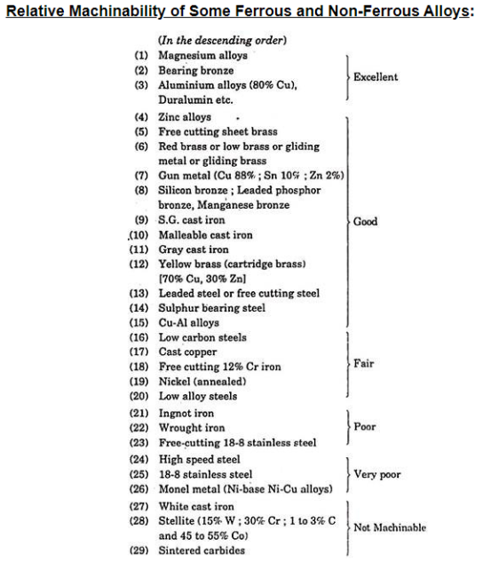
Hard excess carbides or phosphide particles are not present in soft grey cast-irons. Malleable iron is the most machinable of all ferrous materials, and it is frequently preferred over high-sulphur steel. Lead levels in free cutting materials range from 1 to 4%.
Economics of Machinability:
In the vast majority of circumstances, machining is the most cost-effective way of production. When vast amounts of material must be machined, it is critical to make cost-effective component selections.
The various cost elements in machining cost are:
(i) Set up and idle time cost/piece (C1);
(ii) Machining cost/piece (C2);
(iii) Tool changing cost/piece (C3);
(iv) Tool re-grinding cost/piece (C4); and
(v) Too depreciation cost/piece (C5).
Let us consider a case of turning a cylindrical piece of length I mm, diameter D at velocity V m/sec and a feed rate of f m8m/rev. Let us assume that cost/min of labour and overhead is K1. If ts be the time required for set-up and idle time/piece, then set-up and idle time cost per piece. C1 = K1. ts.
If tm = machine time per piece = π Dl.N/f.V (N = no. Of cuts)then machining cost/piece C2 = K1 . tm
If tc is the time required to change a tool, then tool changing cost C3= K1 x tc x no. Of tool changes/piece and no. Of tool changes/piece = tm/T [T = (tool life)]
 C and n are constant for given material

It would be appreciated that cost of re-grinding a tool is made up of two components, viz, K2—the setting cost and K3—cost/mm of tool ground. However, in the case of disposable tips, the cost of re-grinding the tool can be overlooked. Let w be the maximum size of flank wear land on the tool, and = the clearance angle between the tool and the flank wear land. The dotted line represents the metal to be reground from the tool that corresponds to this wear, and it equals w sin.
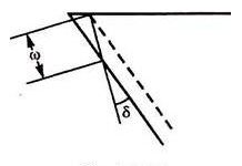
... Tool re-grinding cost/piece
C4 = (K2 + K3w sin δ) x no. Of tool changes/piece

If total amount of material which can be ground off the flank face of new tool before discarding it be M, then:
Permitted number of regrinds 
And total no. Of tool live/tool 
If R be the cost of a new tool, then depreciation cost per tool life:

And tool depreciation cost/piece C5
 no. Of tool changes/piece
... Total cost C = C1 + C2 + C3 + C4 + C5

The variables in the given equation are feed f and velocity V.
Chatter considerations and the geometry of the work piece limit the constant C, which is dependent on tool settings such as nose radius and side-cutting angle.
The value of feed can be increased to reduce machining costs, but it is limited by the maximum feed available on the machine, the surface finish that can be achieved, or the commencement of chatter. Furthermore, a high feed rate is coupled with a low cutting speed, which means the tool is more prone to break due to cutting edge cracking rather than flank wear.
Further high feed and low speed may necessitate more power than the motor can provide. As a result, a suitable maximum feed value must be chosen based on these criteria.
The value of optimum cutting speed depends upon the tool material and work piece material. It has been found that optimum value of speed for solid brazed tools,V = (0.1n/1-n)n C.
Where n and C are the constants dependent upon material, and their values can be determined by tool life tests.
It may be mentioned that selection of optimum speed reduces the tool life and thus may have to be reset frequently which may be costly. Hence overall compromise for the given requirements needs to be made.
1.8.2 What is machinability index of metal?
In various cutting processes, the machinability index is used to compare the machinability of different materials. It is a method of determining the relative machinability of various materials. The machinability rating may differ depending on the cutting operation, such as turning, milling, or shaping. Except for the speed, elements such as tool material, tool geometry, tool life, and other cutting circumstances are fixed when calculating the machinability index. Then, for a certain tool life, determine the speed at which the tool cuts the material. The material is then compared to a standard material. The machinability of standard steel is arbitrarily set to 100% in this example. Low metal removal rate and thus poor machinability are indicated by the slower speed.
Machinability index, 
Vi = Cutting speed of metal investigated for 20 minute tool life
Vs = Cutting speed of standard steel for 20 minute tool life
1.8.3 What are the criteria considered in evaluating machinability?
The parameters listed below must be considered while measuring machinability.
Tool life and the forms of wear that the tool is subjected to Cutting forces, crater wear, flank wear, etc.
Chips' shape, size, and type. The proclivity to burr. Chip cutting ratio.
Chip removal efficiency and rate.
Material quality and qualities of the workpiece
Surface polish and dimensional precision are important factors.
At the cutting zone, the temperature is high.
1.8.4 Machinability of Metals:
The machinability of a work material is directly influenced by the condition and physical qualities of the work material. The various conditions and characteristics described as "condition of work material," individually and in combinations, directly influence and determine the machinability. Operating conditions, tool material and geometry and workpiece requirements exercise indirect effects on machinability and can often be used to overcome difficult conditions presented by the work material. If they are ignored, however, they might create situations that make machining more difficult.
Condition of Work Material
Microstructure, grain size, heat treatment, chemical composition, fabrication, hardness, yield strength, and tensile strength are the eight parameters that affect the state of the work material.
Microstructure: A metal's microstructure refers to its crystal or grain structure as revealed by a microscope inspection of etched and polished surfaces. Metals with similar microstructures have similar machining characteristics. However, differences in the microstructure of a single workpiece can have an impact on machinability.
Grain Size and Structure: A metal's grain size and structure serve as general markers of its machinability. A metal with fine, undistorted grains is easier to cut and finish. This type of metal is both ductile and "gummy." Metals with an intermediate grain size are a good compromise since they can be cut and finished. The hardness of a metal must be connected with grain size, and it is commonly employed as a machinability indicator.
Heat Treatment: When metals are in the solid form, they are sometimes subjected to a series of heating and cooling processes to achieve the desired characteristics. A material can be treated to reduce brittleness, alleviate stress, achieve ductility or toughness, enhance strength, achieve a certain microstructure, adjust hardness, or make other machinability-related changes.
Chemical Composition: A metal's chemical composition is a fundamental determinant of its machinability. Because the components that make up an alloy metal function both separately and collectively, the effects of composition are not always obvious. Certain generalisations about steel chemical composition and machinability can be drawn, but nonferrous alloys are far too numerous and diverse to allow for such generalisations.
Fabrication: The grain size, ductility, strength, hardness, and structure of a metal will be affected by whether it was hot rolled, cold rolled, cold drawn cast, or forged, and therefore its machinability.
The phrase "worked" refers to the hammering or moulding of materials into prefabricated shapes that may be easily transformed into components or products using standard manufacturing methods. Wrought metals are any materials that have been mechanically formed into bars, billets, rolls, sheets, plates, or tubing.
Casting is the process of pouring molten metal into a mould to produce a component shape that requires little, if any, machining. Sand, plaster, metals, and a number of other materials are used to create moulds for these procedures.
Hardness is the ability of a substance to resist deformation, according to the textbook definition. The Brinell or Rockwell scales are commonly used to determine hardness. Hardness is measured by embedding a specified size and shape indenter into the test material's surface and applying a set load or weight. The indenter's depth of penetration into the material surface corresponds to a Brinell or Rockwell hardness reading. The lower the ultimate Brinell or Rockwell number, and hence the lower the associated hardness level, the higher the indenter surface penetration. As a result, high Brinell or Rockwell values or readings indicate a low amount of indenter penetration into the workpiece and, so, are indicative of an exceedingly hard component by definition. The measurement of hardness is depicted.
The Brinell hardness test entails embedding a steel ball of a particular diameter in the surface of a test piece while applying a kilogramme force. By dividing the kilogramme load by the area (in square millimetres) of the circle generated at the rim of the dimple or impression left in the workpiece surface, the Brinell Hardness Number (BHN) is calculated. This standardised procedure allows for uniform comparison testing of a variety of workpiece materials or a single material that has gone through many hardening treatments.
Various indenter sizes and loads can be used in the Rockwell test. For the Rockwell method of hardness testing, there are several distinct scales. In terms of the actual application the test is designed to address,
The three most popular are mentioned below:
Tensile Test Work: Tensile test work is used to compare metal material conditions. These tests can determine a material's yield strength, tensile strength, and a variety of other properties based on its heat treatment. These tests are also used to compare various workpiece materials. In a hydraulic machine, a tensile test is performed by drawing a cylindrical rod or shaft from opposite ends with increasing force. Two marks are made on the rod or shaft, two or eight inches apart, prior to the start of the test. The marks begin to drift farther apart as the rod is progressively subjected to greater stresses. When the load on the rod can be removed and the marks revert to their original distance apart of two or eight inches, the material is said to be in the "elastic zone." If the test is allowed to continue, it will reach a point when the marks will not return to their original distance apart when the load is removed. The test specimen has taken on a permanent set or distortion at this point.
Yield strength: Yield strength is determined right before permanent deformation occurs. Yield strength is calculated by dividing the load just prior to permanent deformation by the cross sectional area of the test specimen in pounds per square inch (PSI). Because it can be changed during heat treatment, this material property is referred to as a condition. Increased component hardness increases yield strength, therefore it takes more force to permanently deform a part as it grows harder. Because these attributes are extremely different and irrelevant to the current issue, yield strength should not be confused with fracture strength, cracking, or the actual breaking of the material into pieces.
Tensile Strength: As a material is heat treated to higher hardness levels, its tensile strength increases along with its yield strength. A tensile test is also used to determine the material condition. The highest load that occurs during a tensile test is divided by the cross-sectional area of the test specimen to determine tensile strength (or ultimate strength). As a result, tensile strength is measured in PSI, just as yield strength. Because its level, like yield strength and hardness, can be varied by heat treatment, this value is referred to as a material condition rather than an attribute. As a result, each hardness rating has different tensile and yield strength levels depending on the material used.
Physical Properties of Work Materials
Physical properties include the modulus of elasticity, thermal conductivity, thermal expansion, and work hardening, which are all included in the distinct material groups.
Modulus of Elasticity: The modulus of elasticity can be determined in the same way as the other criteria during a tensile test.
The modulus of elasticity, unlike hardness, yield, or tensile strength, is a constant material attribute that is unaffected by heat treatment. When a material is subjected to an external force, this attribute indicates the rate at which it will deflect. For metals, this attribute is expressed in PSI, with typical values of several million PSI.
The depth of indentations formed is used to determine hardness.
Thermal Conductivity: Materials are typically designated as heat conductors or insulators based on their thermal conductivity. Conductors move heat quickly from a hot or cold object, but insulators slow down the flow of heat. Thermal conductivity is a measurement of a material's ability to transport heat efficiently. As a result, a material with a relatively high thermal conductivity is termed a conductor, whereas one with a low level is termed an insulator.
Thermal Expansion: As the temperature of a material rises, it expands in size. This is especially true with metals. Thermal expansion is the name given to this physical characteristic. Depending on the type or alloy of metal in question, the rate at which it expands varies. The expansion coefficient of a material can be used to calculate the rate at which it expands. The larger this coefficient, the more a material will expand when exposed to a temperature increase or contract when exposed to a temperature decrease. A 100- bar of steel, for example, would measure 100.065- if the temperature rose by 100 degrees Fahrenheit.
Work Hardening: Many metals have a physical property that causes them to harden dramatically when cold worked. Cold work entails bending, shaping, rolling, or forging a metal object to change its shape. Internal tensions emerge as the metal is formed, causing the portion to harden. Internal hardening varies greatly in rate and magnitude from one material to the next. Heat has a vital influence in a material's work hardening. When materials with work hardening tendencies are exposed to greater temperatures, they function as a catalyst, causing the workpiece's hardness levels to rise.
Metal Machining
When compared to 160 Brinell AISI B 1112 free machining low carbon steel, the term "machinability" is a relative measure of how easily a material may be machined. The American Iron and Steel Institute (AISI) conducted turning tests on B 1112 at 180 surface feet and compared the results to those of other materials. If B 1112 signifies a 100 percent rating, materials with a rating less than 100 percent will be more difficult to machine, while those with a rating greater than 100 percent will be easier.
The normal cutting speed, surface finish, and tool life gained are all factors in a metal's machinability rating. To arrive at a final machinability rating, these elements are weighted and merged. The chart below depicts a variety of materials and their machinability ratings:
Cast Iron
Ferrous materials are any metals that contain iron (Fe). By definition, "ferrous" is "related to or containing iron." Cast iron, pig iron, wrought iron, and low carbon and alloy steels are all ferrous materials. The fact that iron is one of the most abundant metals in nature explains the widespread usage of cast iron and steel workpiece materials.
When iron ore and carbon are metallurgically combined, a wide range of workpiece materials with distinct physical qualities emerge. Hardness, yield, and tensile strengths are all affected by changes in carbon concentration in cast irons and steels. The amount of iron-carbon combinations in cast irons and steels, as well as the manufacturing method, can be changed to alter their physical qualities.
Pig iron is made by combining iron ore and carbon in a series of furnaces. Depending on the manufacturing method, this material can be transformed into cast iron, steel, or wrought iron.
Cast iron is a combination of iron and carbon that is typically used to pour sand castings rather than billets or bar stock. It has outstanding flow qualities, making it a great material for complex cast shapes and complicated moulds when heated to extreme temperatures. Automobile engine blocks, cylinder heads, valve bodies, manifolds, heavy equipment oil pans, and machine bases are all made of this material.
Gray cast iron is a highly adaptable, machinable, low-strength cast iron that is used for pipe, automotive engine blocks, farm equipment, and fittings. The extra carbon in the form of graphite flakes gives this substance its dark grey hue, which also gives it its name.
White Cast Iron: When all of the carbon in a casting is mixed with iron to form cementite, white cast iron is formed. The fast cooling of the casting after it has been poured results in this highly hard substance. Because the carbon in this substance is turned into cementite, when chipped or cracked, the resulting hue is a silvery white. As a result, the moniker "white cast iron" was coined. White cast iron, on the other hand, has essentially little ductility and so fractures when subjected to bending or twisting pressures. When a material with great abrasion resistance is required, the hard brittle white cast iron surface is preferred. Plate rolls in a mill or rock crushers are examples of applications for this material.
Yield strength is determined by pulling a test specimen as illustrated in the illustration.
Malleable Cast Iron: Malleable iron castings are made when white cast iron castings are annealed (softened by heating to a controlled temperature for a set period of time). When hard, brittle cementite in white iron castings is changed into tempered carbon or graphite in the form of spherical nodules or aggregate, malleable iron castings are generated. The end product is a robust, ductile, robust, and machinable material that can be employed in a variety of applications.
Nodular or "ductile" cast iron is used to make a variety of automotive engine components, including cam shafts, crank shafts, bearing caps, and cylinder heads. Heavy equipment cast parts, as well as heavy machinery faceplates and guides, are typically made of this material. Nodular iron is a robust, ductile, tough, and shock-resistant material.
Steel
Steel materials are primarily made up of iron and carbon, with a small amount of alloying elements thrown in for good measure. The carbon content of cast iron components and steel is the most significant difference. Cast iron components are made up of iron and carbon, with a carbon content ranging from 1.7 percent to 4.5 percent. Steel typically has a carbon content of.05 to 1.5 percent. The commercial manufacturing of a large range of steel grades demonstrates the high demand for this adaptable material. Drawing applications for vehicle fenders, hoods, and oil pans employ very soft steels, whereas cutting tools employ top grade high strength steels. Steels are frequently chosen for their electrical characteristics or corrosion resistance. Non-magnetic steels are used in wrist watches and minesweepers, among other applications.
Carbon Steel in its Pure Form: Materials that are a mixture of iron and carbon with no alloying components fall into this group of steels. The ductility (ability to stretch or elongate without breaking) of these materials decreases as the carbon concentration increases. According to the AISI or SAE systems, plain carbon steels are assigned a four-digit code (i.e. 10XX). The carbon content of the substance is indicated by the final two digits of the code in hundredths of a percentage point. A 10 18 steel, for example, contains 0.18 percent carbon.
Alloy Steels: While plain carbon steels are essentially composed of iron and carbon, alloy steels also contain a variety of additional elements. The goal of alloying steel is to improve either its physical qualities or its overall manufacturability. Toughness, tensile strength, hardenability (the relative ease with which a higher hardness level can be achieved), ductility, and wear resistance are among the physical property improvements. Alloying elements can change the final grain size of a heat-treated steel, resulting in a reduced machinability rating for the finished product. Nickel, chromium, manganese, vanadium, molybdenum, chrome-nickel, chrome-vanadium, chrome-molybdenum, and nickel-molybdenum are the most common alloyed steels.
Tool Steels: This class of high-strength steels is commonly used to make cutting tools for metals, wood, and other materials. Furthermore, because to their great hardness and wear resistance after heat treatment, these high-strength materials are used as die and punch materials. Heat treatment is usually required to provide the proper hardness, strength, and wear resistance for any tool steel. These materials are available in a variety of grades with a wide range of chemical compositions to meet specialised as well as general application requirements.
Stainless Steels: As the name suggests, this class of materials is made to withstand oxidation and other forms of corrosion, as well as heat in some cases. Because of the high additions of chromium as an alloying element, these materials have much better corrosion resistance than plain or alloy steel counterparts. Stainless steels are widely utilised to transport corrosive liquids between processing and storage facilities in the food, chemical, and petroleum sectors. Cold formed, forged, machined, welded, and extruded stainless steels are all options. When compared to plain carbon and alloy steels, this group of materials can achieve comparatively high strength values. Stainless steels come in a variety of chemical compositions, up to 150. These materials are available in a wide range of physical qualities to meet the needs of potential consumers and industries. Stainless steels are divided into four types based on their metallurgical properties. Austenitic, ferritic, martensitic, and precipitation hardening are some of the classifications.
Nonferrous Metals and Alloys
Nonferrous metals and alloys include anything from everyday metals like aluminium, copper, and magnesium to high-strength, high-temperature alloys like tungsten, tantalum, and molybdenum. Nonferrous metals and alloys, despite being more expensive than ferrous metals, have major applications due to a variety of features such as corrosion resistance, high thermal and electrical conductivity, low density, and simplicity of production. Tools.
Judging Machinability
The elements that determine machinability have been described, and four ways for judging machinability are mentioned further down:
Tool Life: Metals that can be cut without causing rapid tool wear are considered machinable, and vice versa. The mechanical properties of a workpiece material with many small hard inclusions may appear to be the same as those of a less abrasive metal. During cutting, it may not necessitate any additional power consumption. However, due of its abrasive qualities, this material's machinability would be worse, resulting in faster tool wear and greater machining costs.
Tool life's susceptibility to other machining variables is one issue that arises from its usage as a machinability metric. The impact of tool material is very important. When a high-speed steel tool is used in one situation and a sintered carbide tool is used in another, machinability ratings based on tool life cannot be compared. The machinability of the metal cut with the steel tool would appear to be negative due to the carbide tool's longer life. Even if the same sorts of tool materials are used to evaluate the workpiece materials, the results may be useless. Cast iron carbide cutting grades, for example, will not hold up when cutting steel due to excessive cratering, while steel carbide cutting grades are not hard enough to provide enough abrasion resistance when cutting cast iron.
The cutting tool's life can be defined as the amount of time it works effectively. Cutting tool life is difficult to predict due to numerous variables such as the material to be machined, cutting tool material, cutting tool geometry, machine condition, cutting tool clamping, cutting speed, feed, and depth of cut.
EW. Taylor published the first thorough tool life data in 1907, and his work has served as the foundation for subsequent research. Taylor demonstrated that the relationship between cutting speed and tool life can be mathematically represented as VT = C.
Where V denotes the speed of cutting in feet per minute
T is the tool's life in minutes.
C= a constant that varies according to the work material and other machine parameters.
In terms of numbers, it's the cutting speed that corresponds to one minute of tool life.
n is a constant that varies based on the work and the tool material.
When shown on log-log scales, this equation predicts a linear relationship between tool life and cutting speed. For high-speed steel (HSS) tools, the exponent n is 0.125, while for ceramic tools, it is 0.70.
Tool Forces and Power Consumption: There are two reasons why tool forces or power consumption are used as a criterion for machinability of the workpiece material. To begin, the definition of machinability as the ease with which a metal can be cut means that a metal that can readily be pushed through should have a high machinability rating. Second, in terms of minimum cost per item machined, the more realistic concept of machinability relates to forces and power consumption, as well as the overhead cost of a machine of sufficient capacity.
The cutting force or the thrust force (feeding force) can be utilised as a machinability rating when utilising tool forces. Because it is the force that pushes the tool through the workpiece and determines the power consumed, the cutting force is the more popular of the two. Despite the fact that machinability ratings can be given in terms of cutting forces under a set of typical machining settings, the data is commonly expressed in terms of specific energy. Workpiece materials with a high specific energy of metal removal are said to be less machinable than those with a low specific energy of metal removal.
The use of net power consumption during machining as a measure of the workpiece's machinability is analogous to the usage of cutting force. The information is most valuable in terms of particular energy once again. One benefit of utilising specific energy of metal removal as a machinability indicator is that it is primarily a feature of the workpiece material and is mostly unaffected by tool material. Tool life, on the other hand, is highly reliant on the tool material.
If forces or power consumption are used to determine machinability, the metal removal factor is the reciprocal of the specific energy and can be used directly as a machinability rating. In other words, metals with a high metal removal factor are said to be machinable.
Cutting tool forces were explored. The formulas and calculations for tool force and power consumption are outside the scope of this article; they are covered in works that take a more theoretical approach to analysing metal machinability.
Surface Finish: The machinability rating of a metal can sometimes be determined by the quality of the surface finish left on the workpiece after a cutting operation. Some workpieces are less likely to 'take a good finish' than others. The development and sloughing off of sections of the tool's built-up edge is the primary cause of surface roughness. Soft, ductile materials are prone to forming a built-up edge. Built-up edges are common in stainless steels, gas turbine alloys, and other metals with a strong strain hardening capacity. Built-up edge effects are minimised in materials that are machined with high shear zone angles. Aluminum alloys, cold worked steels, free-machining steels, brass, and titanium alloys are among them. If surface polish were the only criterion for machinability, the latter metals would score higher than the first.
Surface finish is a worthless requirement of workpiece machinability in many circumstances. Roughing cuts, for example, require no attention to complete. The conditions that produce the desired dimension on the part will inevitably offer a satisfactory finish within the engineering specification in many finishing cuts.
Machinability estimates based on surface finish measures don't always match up with estimates based on force or tool life. Any of these requirements would give stainless steels a low rating, while aluminium alloys would receive a high rating. Finish measures would give titanium alloys a high grade, tool life testing a low rating, and force readings an intermediate rating.
It is simple to calculate the machinability rating of various materials based on their surface polish. After standard workpieces of various materials are machined under regulated cutting conditions, surface finish readings are taken with a suitable instrument. The instrument reading has an inverse relationship with the machinability rating. A low reading indicates a high level of machinability and hence a nice finish. The observed value of surface polish can be compared to that of a reference material to get relative ratings.
Chip Form: Machinability grades have been assigned based on the type of chip formed during the machining process. The ease of handling and discarding of chips can be used to determine machinability. A material that creates lengthy stringy chips, as well as one that creates fine powdery chips, would obtain a low rating. Materials that naturally break into neatly broken chips after a half or full turn of the standard chip helix would be given the highest rating. Handling and disposing of chips can be costly. Stringy chips endanger the operator's safety as well as the finish on the recently machined surface. Chip creation, on the other hand, is a function of machine factors as well as workpiece material, and the ratings achieved by this method may be modified if a proper chip breaker was provided.
Ratings based on chip disposal ease are essentially qualitative, and would be assessed by someone who might offer letter gradings of some sort. This approach of interpreting machinability is not widely used. It has some use in drilling, where strong chip creation is required to keep the chips flowing up the flutes. Long coils, on the other hand, whip after they are clear of the hole, which is undesirable.
Key takeaways:
Machinability is defined as the ease with which a material can be machined with the right cutting tool under the right cutting conditions. • The machinability rating is calculated by calculating the weighted averages of normal cutting speed, surface finish, and tool life for each material. It's worth noting that a material with a machinability grade of less than 100 percent would be more difficult to machine than B1112, whereas one with a number more than 100 percent would be simpler.
1.9.1 What is tool life?
Tool life is a critical aspect in machinability evaluation; it is the amount of time that the tool cuts successfully and efficiently. The time between two successive tool grindings and two successive tool replacements is known as tool life. The tool life of a cutting tool should be long. Because grinding and replacement costs are so high, a short tool life is uneconomical. Today's tool material advancements extend the tool's life.
It is said that a tool has reached the end of its useful life when it no longer performs the desired function. The following symptoms suggest that the tool's useful life has come to an end.
On the workpiece, there is a poor surface polish, dimensional inaccuracy, and chatter marks.
Friction causes overheating of the workpiece-tool interface.
Cutting edges that have become soiled.
An surge in power use that happens all of a sudden.
1.9.2 Taylor formula for Tool life
The various ways of describing the tool's life cycle
The tool life can be expressed in a variety of ways, including
The most widely used tool life unit is the time unit.
The amount of material removed by a tool over the course of its life.
The number of workpieces that a tool has machined.
The predicted life of several tool materials is provided below. Tool life is most usually represented in minutes.
120 minute cast tool steel
60 to 120 minutes using a high-speed steel tool
Tool made of cemented carbide - 420 to 480 minutes
The level of machining parameters, such as cutting velocity (V C), feed (S 0), and depth of cut (D 0), determine the wear and hence tool life of any tool for any work material (t). Cutting velocity has an impact on the maximum and minimum cut depths.
In Fig, the typical pattern of cutting tool wear (mostly VB), the basis of determining tool life, and its relationship to cutting velocity are graphically depicted.
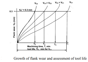
When seen in Fig, tool life reduces as cutting velocity increases, while other variables remain unchanged.
If the tool lives, ,
, ,
,  ,
, etc are plotted against the corresponding cutting velocities,
  ,
,  ,
,  ,
,  etc as shown in Fig, a smooth curve like a rectangular hyperbola is found to appear. When F. W. Taylor plotted the same figure taking both V and T in log-scale, a more distinct linear relationship appeared as schematically shown in Fig.
With the slope, n and intercept, c, Taylor derived the simple equation as

Taylor's tool life exponent is denoted by the letter n. The values of both ‘n' and ‘c' are largely determined by the materials used in tooling and the cutting environment (cutting fluid application). C's value is likewise influenced by undertaken's limiting value (i.e., 0.3 mm, 0.4 mm, 0.6 mm etc.).
1.9.3 Factors affecting tool life
The tool's life will be influenced by a number of elements, which are listed below.
Material for the tool and its qualities
Work piece material properties include tensile strength, hardness, and microstructure, as well as the degree of heat treatment applied to the material.
The product must have a finish.
Tool geometry refers to the cutting tool's profile.
Temperature and cutting fluid utilised throughout the machining process.
Feed, cutting speed, and cut depth are all machining factors.
Continuous and intermittent cutting are two types of machining operations.
1.9.4 Why a blunt cutting tool is not preferred to smooth cutting tool?
It is critical that the tool face be as smooth as possible in order to achieve a long tool life.
Because of the faults listed below, a blunt tool has a shorter tool life.
When the friction between the tool and the workpiece is increased, the tool becomes overheated.
Cutting forces have increased, as has power usage.
During machining, it generates vibrations.
1.10.1 Measuring the cutting force:
Experiments have revealed that the frontal area of the uncut chip is approximately proportional to the tangential component of the cutting force (FT) in metal cutting. The proportionality constant is material particular and is commonly referred to as the particular power (Ks). That is to say,
FT = Ksbh
Where h is the chip thickness and b is the chip breadth.
For a vast range of workpiece materials, nominal Ks values have been tabulated. In most cases, the normal component of the cutting force (FN) is around 30% of the tangential component. That is to say,
FN = 0.3FT
Surprisingly, the link between material removal rate and power is expressed by the same proportionality constant, Ks. That is to say,
P = Ks(mrr)
The cutting zone is a harsh environment. The installation of any form of sensor is difficult due to the moving tool, chips, coolant, and heat. So, how are cutting force measurements determined? Is it possible to take measurements all the time when the machine is running? If the cutting force were available during production, it would be possible to detect tool wear, broken teeth, contact between the tool and workpiece, for example, and easy to determine Ks for a new material.
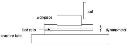
Figure. A table-type cutting force dynamometer.
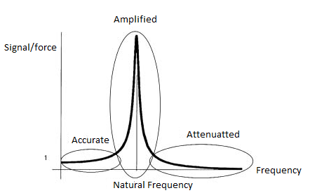
Figure. A simplified table-type dynamometer frequency response function.
A cutting force dynamometer is used to measure the cutting force at a short distance from the cutting zone (Figure). The dynamometer for milling is typically made up of two flat plates sandwiching three or four piezoelectric load cells. The load cells' sensing elements are flat bits of ceramic crystal. The piezoelectric effect occurs when ceramic components are distorted, which means they produce an electric charge that can be amplified into a voltage proportionate to the force that created the distortion. The workpiece is fastened to the top plate of the dynamometer, which is secured to the table. The load cells are fitted with a large preload force to ensure that they are always in contact with the plates.
The load cells are stiff, but not inexhaustibly stiff. Small vibrations of the top plate relative to the bottom plate are caused by the cutting force between the tool and the workpiece (proportional to the stiffness of the load cells). The load cell deforms as a result of the little motion, and the deformation generates the measurement signal.
The table-type dynamometer, as useful as it is, has limits. It takes up portion of the available space. Because the piezoelectric components are sensitive to liquids, the gap between the plates must be sealed. The piezoelectric crystals differ somewhat, and these changes, together with tiny misalignments of the load cells, alter the dynamometer's sensitivity in the table's coordinate directions. As a result, the dynamometer will need to be calibrated.
The most perplexing issue, however, is bandwidth, which stems directly from the basis of operation. The piezoelectric elements are flexible but stiff springs because they must deform to produce a signal. Because the top plate has mass, the dynamometer is essentially a mass on springs. It has a natural frequency that it like to vibrate at. It features a frequency response function, which means that depending on the frequency of the cutting force, the dynamometer amplifies or attenuates the signal (Figure).
The dynamometer faithfully transmits the cutting force signal if the frequency of the cutting force is low. The cutting force signal is amplified—sometimes dramatically—if the frequency of the cutting force is near to the natural frequency of the dynamometer system. The cutting force signal is attenuated—sometimes significantly—if the cutting force is well beyond the dynamometer system's inherent frequency. As a result, dynamometer designers strive for the highest natural frequency feasible. They select load cells that are extremely rigid and instal them with a high preload. They attempt to keep the top plate's mass as low as feasible. Typical dynamometer manufacturers claim bandwidths of 2,000 to 3,000 Hz (the region of the useful leftmost ellipse in Figure).
Users of dynamometers should be aware that the band width quoted is without any weight on the top plate. The workpiece and mounting hardware contribute bulk to the top plate, lowering the natural frequency and shifting the peak to the left, reducing the useable bandwidth.
The natural frequency with the workpiece installed is frequently well below 1,000 Hz for practical applications. The tooth passing frequency for a spindle revolving at 24,000 rpm and holding a tool with two teeth is 800 Hz, hence the peak in the figure must be much greater. Cutting force measurements are not commonly accessible in production machine tools due to dynamometer bandwidth limitations. CTE
1.10.2 Lathe tool dynamometer:

A lathe tool dynamometer is a piece of equipment that uses strain gauges to measure the amount of load acting on the tool while it's in use.
1.10.3 Drilling dynamometer:
Figures demonstrate the schematic and pictorial construction of a strain gauge type 2 – D drilling dynamometer for measuring torque and thrust force. Four strain gauges are mounted on the upper and lower surfaces of the two opposite ribs for Px – channel and four on the side surfaces of the other two ribs for the torque channel. The dynamometer must be calibrated before use so that the real values of T and Px may be determined from the voltage values or readings taken in SMB or PC.
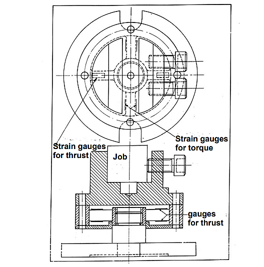
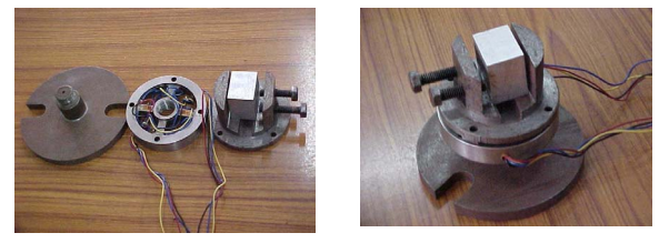
1.11.1 Economics of Machining – Cutting Time, Tool Changing Time, Idle Time:
Machining, often known as metal cutting, is an integral part of the manufacturing process. The ultimate goal of machining is to gradually remove material from a workpiece to achieve the desired form, size, and finish. Removing the material, establishing the work and cutting tool, and shipping the machined task all take time that isn't insignificant. Overall machining or cutting time must be accounted for when planning the complete process.
Industry's key goal these days is to produce a product at a faster rate but at a lower cost, all while maintaining product quality. If traditional machining is used, the cutting speed and feed rate must be raised in order to meet the first criteria (faster production rate). However, because of the greater wear rate and higher heat output, this may result in a shorter cutting tool life. As a result, cutting tools must be changed regularly, resulting in a loss for the industry due to idle time spent changing tools. The cost of the tool is likewise not insignificant. As a result, a drastic increase in cutting speed and feed rate is not a viable solution; instead, optimization is required.
Overall machining time and cost
In today's competitive market, time is worth the same as money. Essentially, total machining time (Tm) is the sum of three distinct time factors intimately related to the machining or metal cutting process. Actual cutting time (Tc), total tool changing time (Tct), and other handling or idle time are the three elements (Ti). Aside from these three time considerations, the cost of the cutting instrument must be factored into any optimization. Except for handling time, all of these time or cost variables are modified by changes in cutting speed and feed rate, as discussed below. Total machining time (Tm) can be stated mathematically as:
Tm = Tc + Tct + Ti
What is actual cutting time (Tc)?

Cutting time, as the name implies, is the time spent actually removing material, i.e. from the start of chip creation until the end of uninterrupted machining. The pause duration will not be included in this time factor whether there is a deliberate or inadvertent delay in cutting. As a result of the increased cutting speed and feed rate, the actual cutting time will be reduced as the material removal rate (MRR) increases. As a result, if the speed or feed is increased, the cost associated with cutting time will drop. The diagram on the right shows how the cost of actual cutting time varies depending on the speed or feed used during machining.
Mathematical expression of actual cutting time
If, Lc is the total length of cut (mm), N is the spindle speed (rpm) and s is the feed rate (mm/rev), then estimated uninterrupted cutting or machining time can be expressed as:

The spindle speed (N) and cutting velocity (Vc) are interchangeable in most circumstances where either the workpiece or the cutting tool is rotating. Cutting velocity, on the other hand, is influenced by the job/cutter diameter (D). Cutting velocity can be stated as follows in terms of speed and task or cutter diameter (whichever is spinning). You can learn more about this conversion by reading Cutting speed and cutting velocity in machining.

In case of turning or milling, actual cutting time can be expressed as:


What is tool changing time (Tct)?

Every tool has a specific life span during which it may work adequately, and once that life span is exceeded, replacement or re-sharpening is required. Cutting or machining operations must also be paused for a period of time. Increases in cutting speed or feed rate diminish tool life (as demonstrated by Taylor's Modified Tool Life Equation), necessitating more frequent tool changes. The industry will suffer losses as a result of these unplanned and frequent machining interruptions. The diagram to the right shows how the cost of tool changing time varies depending on the machining speed or feed.
Mathematical expression of tool changing time
Because every cutting tool has a finite life (known as Tool Life - TL), it may be necessary to change the cutting tool before the process is completed. Occasionally, a tool must be changed many times. As a result, the number of tool changes necessary is determined by the actual machining time.
If TCT is the average time an operator or automation system (such as an automated tool changer – ATC) takes to change a tool, then tool changing time (Tct) can be stated mathematically as follows. Essentially, it is the multiplication of one tool change time (TCT) by the number of times such tool changes are requested within the stipulated cutting time (Tc).

What is part handling time or idle time (Ti)?

This time factor is influenced by the workpiece and its configuration, as well as the material handling method used. It handles task loading and unloading and is unaffected by the cutting velocity or feed rate used throughout the machining process. Because the equipment is idle during loading and unloading, it is sometimes referred to as idle time. The diagram below shows how the cost of idle time varies depending on the speed or feed used during milling. Its value must be obtained directly from a database, direct measurement, or experience because it is independent of cutting parameters.
Tooling cost – cost of the cutting tool
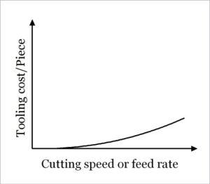
Tooling cost, while not directly related to cutting velocity, plays a role in overall machining efficiency. If you use a greater speed or feed, you'll get faster tool wear and shorter tool life, which will increase your costs because you'll need more tools to cut the same length. The diagram on the right shows how tool cost fluctuates depending on the machining speed or feed.
The cost of tooling is estimated by multiplying the price of a single cutting tool (K2) by the number of tools required. By dividing actual machining time by tool life, the quantity of tool required can be calculated once more. The formula for calculating tooling costs is as follows:
Tooling cost 
Overall machining time and cost
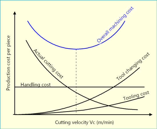
Because each time element related to machining contributes to the cost of machining, some criteria are required to convert time to cost. Time elements can be transformed to cost elements using these parameters, making machining economy estimate easy. Among these are the following:
● K1 = Cost-time conversion factor for machining
● K2 = Cost-time conversion factor for tool sharpening or price of new tool.
Therefore, overall machining cost per piece (Cp)
= (Actual cutting cost/piece) + (Tool changing cost/piece) + (Handling cost/piece) + (Tooling cost/piece)
= K1 {(Actual cutting time/piece) + (Tool changing time/piece) + (Handling time/piece)} + K2 {(Tooling cost/piece)}

Finding out economic condition and Gilbert’s Model
The final step is to determine the best conditions for either maximising profit or reducing time requirements. To keep the analytical method simple, only cutting velocity or speed is evaluated for paper-based optimization. Furthermore, cutting velocity is the most important factor influencing machining performance. Computer programming-based optimization strategies can efficiently address a variety of restrictions.
There are now a number of optimization objectives, the most renowned of which are Gilbert's Model (1952) for Maximum Production Rate and Minimum Production Time. These models are based on Taylor's Tool Life equation, which determines tool life solely based on cutting velocity. Below are many economic methods for optimising machining process parameters for various goals. The links below will take you to a full examination of such optimization.
Numericals:
Question 1:
The uncut chip thickness in orthogonal machining with a tool with a 9° orthogonal rake angle is 0.2mm. The thickness of the chip varies between 0.25mm and 0.4mm. In this situation, find the ratio of the highest shear angle to the minimum shear angle.
Solution: Machining is a subtractive manufacturing process in which material is gradually removed from the workpiece by shearing while the cutting tool exerts compressive stress. Shear plane refers to the supposed plane along which shearing occurs. Shear angle refers to the angle of this shear plane with respect to the cutting velocity vector. As shown below, the orthogonal shear angle ( ) can be defined in terms of the orthogonal rake angle (
 ) and the chip reduction coefficient (
 ).
).

 = Orthogonal shear angle
 = Orthogonal rake angle
a1 = Uncut chip thickness
a2 = Chip thickness > a1
Chip reduction coefficient  > 1
> 1
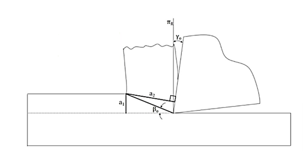
When a specific tool is selected for machining, the rake angle of the cutting tool falls under tool geometry and can be classified as an independent variable. However, the chip reduction coefficient ( ) is a variable that is influenced by a number of factors. Chip reduction coefficient is defined as the ratio of chip thickness (a2) to uncut chip thickness (a1) (a1). Because of lamellar shearing and straining in traditional macro-scale cutting, chip thickness is always greater than uncut chip thickness (i.e. a2 > a1). Mathematically,
ζ = (a2 / a1) > 1
In this situation, the uncut chip thickness (a1) is 0.2mm, and the orthogonal rake angle ( ) is +9 degrees. As a result,
  is inversely proportional to
  from the generic expression of shear angle (
 ) given at the beginning. In addition,
  is inversely proportional to a2.


Question 2:
Since shear angle is inversely proportional to the chip thickness, so maximum shear angle can be obtained for minimum value of chip thickness for a constant uncut chip thickness. This in this particular case as given in question, maximum shear angle will be correspond to the 0.25mm chip thickness. So for γo = 9°, a1 = 0.2mm and a2 = 0.25mm, let us calculate maximum shear angle.


Question 3:
Opposite to the maximum shear angle, the minimum shear angle will be obtained for maximum value of chip thickness. Here the maximum chip thickness is given as 0.4mm. Therefore, for γo = 9°, a1 = 0.2mm and a2 = 0.40mm, let us calculate minimum shear angle.


Question 4:
The maximum and minimum shear angles for the given situation have already been determined. The ratio between them can also be simply determined, as stated in the question.

Question 5:
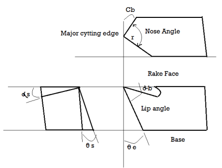
Where, αb = Back rake angle θe = End relief angle
 s = Side rake angle θs = Side relief angle
Ce = End cutting edge angle r = Nose radius.
Cs = Side cutting edge angle
ASA System: αb - αs - θe - θs - Ce - Cs – r
• In the ASA system, angles are expressed in terms of three mutually perpendicular planes.
• Angle measurement and signalling will be easier because the angles are measured w.r.t. Three mutually perpendicular planes.
• The development of a chip and how it behaves during machining is largely determined by the tool's principal cutting edge. As a result, the tool's basic geometric parameters are measured in relation to the principal cutting edge.
• As a result, machining analysis will be difficult if the tool is specified in the ASA system.
While machining steel with a tool of [0-10-6-6-8-75-1] ORS shape following observation were made,
- Spindle speed 300 rpm
- Work diameter 40 mm
- Depth of cut 3.5 mm
- Tool feed rate 70 mm / min
- Cut chip thickness 0.55 mm
Determine:
- Chip thickness ratio
- Shear plane angle
- Dynamic shear
- Theoretical continuous chip length per minute
Solution:
Data:
From tool designation α = 10 degree
N = 300 rpm, D = 40 mm, t=w=3.5 mm, t2 = 0.55 mm

To find (1) r = ? (2) p = ? (3) V (4) L2
1) Chip thickness ratio (r):

2) Shear plane angle (p):


3) Dynamic shear strain:


4) Theoretical continuous chip length per minute:
Chip length before cutting 

 mm/min
Now,
 Here
Here  Theoretic chip length per min.

 mm/min
Question 6:
An orthogonal cut is made with a carbide tool having a 15° positive rake angle. The various parameters were noted,
- the cut width was 0.25"
- the feed was set at 0.0125"
- the chip thickness was measured to be 0.0375"
- the cutting speed was 250 ft./min.
- the forces measured were Fc = 375 lb. And Ft = 125 lb.
a) Use Merchant's Circle to scale, and the velocity diagram
b) From the Merchant Circle diagram find the shear angle (), friction force (F), friction normal force (N), and shear force (Fs).
c) From the Velocity diagram find the friction velocity (Vf).
d) Calculate values for the coefficient of friction (mu) and the metal removal rate.
e) Calculate values, and compare the results for the results found in a), b) and c).
(Ans: F = 218lb., N = 330lb., = 19.37°, Fs = 312 lb., = 0.948, Vc = 250 ft./min., Vf = 83.5 ft./min. Q = 9.375 in3/min.)
Question 7
What are the functions of rake and relief angles in cutting tools?
Ans. The basic cutting parameters will alter depending on the rake angle. Cutting forces are lower with a positive rake (sharp tool), but edge strength is lower. A negative or neutral rake produces more cutting forces but also more strength. The relief angle creates a space behind the cutting edge, preventing the tool from rubbing against the job.
Question 8
Which of the following statements is the most accurate?
a) a continuous chip with built up edge may result when we try to cut too much metal.
b) When cutting very brittle work materials, a continuous chip will develop.
When we employ fine feeds and speeds, we will get a discontinuous chip.
c) none of the aforementioned options.
Ans. a
Question 9
a) The rake angle is positive, which is one of the assumptions of orthogonal cutting.
b) the instrument only has one edge and one point for cutting.
c) The shear plane is a function of chip thicknesses before and after shearing.
d) none of the aforementioned options.
Ans. b
Question 10
Which of the following assertions is true?
a) As the cutting velocity increases, the cutting pressure decreases.
b) As metal temperature and cutting velocity rise, the amount of power required decreases.
c) We can estimate the needed horsepower of a machine tool based on the amount of metal removed alone.
d) all of the aforementioned.
Ans. a
Question 11
A pipe piece with an inner diameter of 6" and an exterior diameter of 6.25" is being cut with a lathe toolbit with a rake angle of 20°. The chip has a thickness of 0.020" and the cut depth is 0.010". If the lathe spins at 200 rpm and the cutting forces measured are Fc = 300 lb and Ft = 125 lb,
a) What assumption must you make.
b) Find the following values using a graphical or numerical solution: (Marks are only awarded for correct answers) Fs, FN, F, N, , , , Vc, Vf, Vs.
c) What is the minimum horsepower required for the machine?
d) Given that the tube is aluminium, use another method to find the required horsepower.
Ans:


a) Reasonable assumptions are that we are performing orthogonal cutting. This means that we are cutting fully through the wall of the tube. We also want to assume that the effects of different cutting speeds from the inside to the outside of the tube are negligible.


For an efficient machine with no idle horse power.


Question 12
a) Why are ceramics normally provided as inserts for tools, and not as entire tools?
b) List the important properties of cutting tool materials and explain why each is important.
Ans.
a) Ceramics are brittle materials and cannot provide the structural strength required for a tool.
b) Hardness at high temperatures-this provides longer life of the cutting tool and allows highter cutting speeds.
Toughness-to provide the structural strength needed to resist impacts and cutting forces wear resistance – to prolong usage before replacement doesn’t chemically react-another wear factor
Formable/manufacturable-can be manufactured in a useful geometry.
Question 13
With a feed rate of 0.050ipr, a turning cut was achieved in a magnesium workpiece. The cutting speed was 300 feet per minute, and the cutting force was 200 pounds. The lathe is 95% efficient and has a 0.1 horsepower idle horsepower. Estimate the horsepower necessary for the cut using all of the information provided.
Ans:


Question 14
Using the formulae for orthogonal cutting power, create an expression that represents the ratio of friction power to cutting power. Make the phrase more straightforward by expressing it in terms of measured values (rake angle, Fc, Ft, and chip thicknesses).
Ans


Question 15
Which of the following statements is the most accurate?
a) a continuous chip with built up edge may result when we try to cut brittle metals.
b) a continuous chip will result when cutting very strong work materials.
c) a discontinuous chip will result when we use heavy feeds and speeds.
d) all of the above.
Ans. C
Question 16
When computing orthogonal cutting forces, one of the assumptions is that
a) that the rake angle is positive.
b) that the tool is only cutting with one edge and one point.
c) the shear plane is a function of before and after chip thicknesses.
d) none of the above.
Ans. C
Question 17
Which of the following assertions is the most accurate?
a) the cutting pressure drops as cutting velocity decreases.
b) power required to cut each cubic inch drops as cutting velocity increases.
c) we can use the quantity of metal removed by itself to estimate the required horsepower of a machine tool.
d) all of the above.
Ans. B
Question 18
On cast iron work with a 6" diameter, a new lathe tool will be used to make a 36" long rough cut in four passes. The following operating conditions were specified by the supplier or assumed. As requested, calculate the parameters a) to e).
Cutting Speed = 200 fpm
Feed Rate = 0.010 ipr
Depth of Cut = 0.100"
Idle Horse Power = 0.25
Machine Efficiency = 0.90
a) Spindle RPM
b) Time to make the cut (min.)
c) Metal Removal Rate Q (in.3/min.)
d) Cutting Horse Power (HPc)
e) Minimum Machine Tool Motor Horse Power.
Ans. a) 127rpm, b) 113min., c) 2.4 ipm, d) 1.23 or 3.94HP, e) 1.62 or 4.63HP


 (for one pass)


References:
- Book: Non-traditional Manufacturing Processes by G. F. Benedict (Manufacturing Engineering and Materials Processing-19).
- Book: Unconventional Machining Processes by T. Jagadeesha (I. K. International Publishing House Pvt. Ltd.).
- Book: Advanced Machining Processes by V. K. Jain (Allied Publishers Private Limited).
- Book: Nonconventional Machining by P. K. Mishra (Narosa Publishing House).
- Paper: M. W. Chastagner and A. J. Shih, Abrasive Jet Machining for Edge Generation, Transactions of NAMRI/SME, Volume 35, 2007.
- Paper: I. Finnie (1972); Some observations on the erosion of ductile metals; Wear; Vol. 19 (1), pp. 81-90.