Unit – 2
Conventional machining process and machine tools
2.1.1 Conventional machining
In addition to contemporary CNC machines, we also have traditional machining machines that are critical to our manufacturing. They're utilised to make spare parts and smaller batches of products (even one piece) that are just as important in various productions.
Despite the fact that some series are tiny, they require a wide range of machining operations and precision, which we can provide with the following machines:
1. TURNING
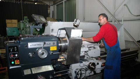
We have a variety of traditional turning lathes. The largest one can turn workpieces up to 400 mm in diameter and 2000 mm in length, and/or up to 800 mm in diameter and 350 mm in length. This machine was manufactured in 2013, and it features a 4-clamping jaw, various steady rests, and digital measuring sticks.
Turning is a machining method in which the workpiece is spun as cutting tools travel across it on a lathe. To make cuts with exact depth and width, the cutting tools move along two axes of motion. Traditional manual lathes and automated computer numerical controlled (CNC) lathes are the two types of lathes available.
The turning technique can be applied to the outside or inside of a material. When done on the inside, it's referred to as "Boring”—the most frequent way for producing tubular components (which can be horizontal or vertical depending on the spindle orientation). The term "turning process" refers to another aspect of the process "During the early and last stages of the turning process, the cutting tool goes across the end of the workpiece, a process known as "facing." Only a lathe with a fitting cross-slide can be used for facing. It is used to create a perpendicular to the rotational axis datum on the face of a casting or stock shape.
Turret lathes, engine lathes, and special purpose lathes are the three types of lathes that are commonly used. Engine lathes are the most frequent type used by hobbyists and general machinists. Turret lathes and special purpose lathes are more typically employed for pieces that must be manufactured repeatedly. A tool holder on a turret lathe allows the machine to complete multiple cutting operations in a row without interruption from the operator. Disc and drum lathes, for example, are used in an automotive garage to reface the surfaces of brake components.
CNC mill-turning centres combine typical lathe head and tail stocks with additional spindle axes to enable efficient machining of items with rotational symmetry (such as pump impellers) and the milling cutter's ability to manufacture complicated features. 5-axis machining allows complex curves to be generated by rotating the workpiece around an arc while the milling cutter goes along a different path.
2. MILLING
The INAS universal milling machine features a 1100x300 mm table as well as a manifold.
In contrast to turning processes, where the tool does not spin, milling removes material using revolving cutters. The workpieces are positioned on moving tables in traditional milling machines. The cutting tools are stationary on these machines, while the table moves the material to make the desired cuts. Tables and cutting tools are both moveable components on other milling machines.
Slab milling and face milling are the two most common milling techniques. Slab milling employs the milling cutter's peripheral edges to make flat cuts over a workpiece's surface. A comparable cutter, but thinner than a standard slab cutter, can be used to cut keyways in shafts. Face cutters, on the other hand, utilise the milling cutter's end. Special cutters, such as ball-nose cutters for milling curved-wall pockets, are offered for a range of purposes.
Planning, cutting, rabbeting, routing, die-sinking, and other operations are among the capabilities of a milling machine, making it one of the more versatile pieces of equipment in a machine shop.
Hand milling machines, plain milling machines, universal milling machines, and omniversal milling machines are the four types of milling machines, and they all have horizontal cutters or cutters mounted on a vertical axis. The universal milling machine, as expected, can accommodate both vertical and horizontally mounted cutting tools, making it one of the most complicated and versatile milling machines on the market.
Milling machines capable of performing a sequence of operations on a part without the participation of an operator are ubiquitous, and are sometimes referred to as vertical or horizontal machining centres. They're almost always CNC-based.
3. DRILLING
Boreholes and thread cutting can be made in any type of workpiece using various drilling machines.
Drilling uses drill bits to generate cylindrical holes in solid materials; it is one of the most essential machining techniques since the holes formed are typically used to aid with assembly. Drill presses are frequently employed, however lathes can also be employed. Drilling is a preparatory step in most manufacturing operations for producing finished holes, which are then tapped, reamed, bored, etc. to generate threaded holes or bring hole dimensions within acceptable tolerances. Due to the bit's flexibility and tendency to seek the route of least resistance, drill bits will frequently cut holes that are larger than their nominal size and holes that are not always straight or round. As a result, drilling is frequently specified undersize and followed by a machining process to bring the hole to its final size.
Two helical grooves run up the shaft of the drill bits that were employed. As the bit penetrates into the material, the "fluting" carries the chips, or swarf, out of the hole. There is a recommended drill speed and feed for each type of material.
Boring is used to refine the dimensions and accuracy of a drilled hole, despite the fact that drilling and boring are frequently confused. Boring machines are available in a variety of sizes, depending on the size of the job. The work rotates while the boring bar remains stationary in a vertical boring mill, which is used to make very big, heavy castings. Jig borers and horizontal boring mills keep the work immobile while rotating the cutting tool. Boring can also be done in a machining centre or on a lathe. Boring cutters often mill the side of the hole with a single point, allowing them to act more firmly than drill bits. Boring is commonly used to complete cored holes in castings.
Machine and hand reamers are also used to finish holes, resulting in a smoother surface than can be attained by boring alone. Standard reamers are offered in 1/64-inch increments. Straight or helically fluted reamers are cut on the periphery, removing only 0.004-0.008 in. Of the bore. Boring and reaming are done using the same machine tools, and reaming is sometimes done in a drill press.
4. SLOTTING
External and internal slotting is available for nuts with a width of 30 mm and a length of 250 mm.
5. GEARING
We can produce straight or helical teeth up to 300 mm and module 5 with our gearing machine MAAG.
Products created on these machines are primarily utilised as spare parts for other machines and devices, but they are also employed as the basis for the initial inclusion into machines for a specific purpose in a variety of industries, including medicine, manufacturing, agriculture, and construction.
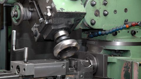
6. GRINDING
Grinding is a technique for removing small amounts of material from flat and cylindrical surfaces. Surface grinders feed work from a table into a grinding wheel in a reciprocating motion. The cutting depth of the wheel is normally between 0.00025 and 0.001 inch. Cylindrical grinders rotate the workpiece while applying the periphery of a revolving abrasive wheel on it. Centerless grinding is a technique for mass-producing small parts in which the ground surface has no link to any other surface other than itself. For many applications, ground surfaces of 200-500 min. Rms are normally deemed satisfactory, and they serve as a starting point for subsequent finishing operations like as lapping, honing, and superfinishing.
7. PLANNING
Planning is typically used to mill large flat surfaces, especially those that will be scraped, such as machine tool paths. Small pieces that are ganged together in a fixture are also planned economically.
Key takeaways:
• Thermal, chemical, and electrical energy are the three basic types of energy employed in non-conventional machining. Examples. Turning, boring, milling, shaping, broaching, slotting, grinding, and other traditional machining processes are examples.
• A human operator directs and controls machining equipment such as milling, boring, and drilling machines, as well as lathes and other sharp cutting instruments, in the traditional machining process.
2.1.2 Machining Process Definition:
Machining is a technique that involves cutting a piece of raw material into the required form and size with sharp cutting tools.
2.1.3 Types of Machining Operations:
The machining process is divided into two types.
1. Conventional Machining Process
The following are the traditional machining procedures.
Drilling Operation:
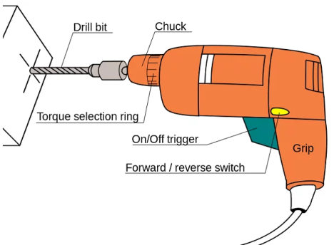
It removes material from the surface of the workpiece in the form of holes using a multi-point cutting tool, commonly known as a Drill bit.
When compared to operating with a single-point cutting tool, the MRR (Material Removal Rate) of the drilling operation is extremely high.
Table Clamp, Vertical Column, Base, Swivel Table, Power Transmission system (Stepped Cone Pulley), Drill Feed Handle (Hand Wheel), Spindle, Chuck, and Drill bit are the components of a drilling machine.
Boring Operation:
Boring is a type of drilling technique that involves enlarging a previously drilled hole.
Milling Operation:
Milling is an operation that uses rotary cutters such that it can advances into the work material.
A milling procedure can be used to create grooves in the work material.
Turning Operation:
Turning is a lathe operation that removes material from the surface of the workpiece so that the diameter of the component is reduced to the desired value.
2. Unconventional Machining Process:
A step up from traditional machining procedures.
USM (Ultrasonic Machining):
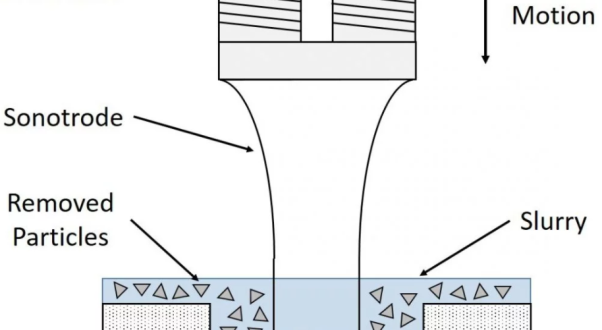
It is one of the sorts of unusual machining methods capable of producing circular and non-circular holes as small as 1mm in diameter.
This tool will apply impact loads to the abrasive particles, which will then apply impact loads to the workpiece, allowing for machining.
Electrical Discharge Machining Process:
The procedure is also known as Spark Machining.
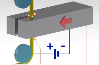
In this method, electrical energy is used to establish a Spark between the tool and the workpiece, which is submerged in a dielectric media, allowing material to be removed from the workpiece's surface via local melting or vaporisation.
Let's look at the benefits, drawbacks, and applications of the machining process...
2.1.4 Advantages of Machining Process:
The advantages of machining process are as follows.
• A high-quality surface finish can be achieved.
• Machining can be used on a variety of materials, including wood, plastic, composites, and ceramics.
• Geometry details such as screw threads, very straight edges, accurate round holes, and so on are all feasible.
• Excellent dimensional correctness.
2.1.5 Limitations of Machining Process:
The limitations of machining process are as follows.
• The operator's efficiency determines the precision of the components produced.
• There is no production consistency. As a result, a complete inspection of the component is required.
•The operator's personal requirements are lowering output rates.
• The labour problem will be severe due to the significant volume of manpower required.
• Manufacturing complicated shapes such as parabolic Curvature components and Cubicle Curvature components is tough.
• The component's frequent design modifications can't be accommodated in the current layout.
2.1.6 Applications of Machining Process:
The applications of machining process are as follows.
• Machining can be done on a variety of components using either traditional or unorthodox methods.
• The machining can be done on a lathe, milling machine, ultrasonic machining machine, and so on.
• Machining advancements can be made on CNC machines without the need for human interaction.
2.2.1 Machine tool:
Any stationary power-driven equipment used to shape or create pieces made of metal or other materials is referred to as a machine tool. The shaping is accomplished in four general ways: (1) by cutting excess material in the form of chips from the part; (2) by shearing the material; (3) by squeezing metallic parts to the desired shape; and (4) by applying electricity, ultrasound, or corrosive chemicals to the material. The fourth category includes modern machine tools and technologies for machining ultrahard metals that are difficult to machine using traditional methods.
Lathes, shapers and planers, drilling machines, milling machines, grinders, and power saws are examples of machine tools that produce parts by removing metal chips from a workpiece. Punch presses are used to cold form metal pieces such as cooking utensils, automotive bodies, and other similar objects, whereas forging presses are used to hot form white-hot blanks into correctly shaped dies.
Modern machine tools can cut or mould items to tolerances of one tenth of an inch or less (0.0025 millimetre). Precision lapping machines may create pieces that are within two millionths of an inch in particular applications (0.00005 millimetre). Machine tools combine weight and stiffness with delicate accuracy due to the precise dimensional requirements of the parts and the powerful cutting pressures exerted on the cutting tool.
Turning
Turning is a machining method in which the workpiece is spun as cutting tools travel across it on a lathe. To make cuts with exact depth and width, the cutting tools move along two axes of motion. Traditional manual lathes and automated computer numerical controlled (CNC) lathes are the two types of lathes available.
The turning technique can be applied to the outside or inside of a material. When done on the inside, it's referred to as "Boring”—the most frequent way for producing tubular components (which can be horizontal or vertical depending on the spindle orientation). The term "turning process" refers to another aspect of the process "During the early and last stages of the turning process, the cutting tool goes across the end of the workpiece, a process known as "facing." Only a lathe with a fitting cross-slide can be used for facing. It is used to create a perpendicular to the rotational axis datum on the face of a casting or stock shape.
Turret lathes, engine lathes, and special purpose lathes are the three types of lathes that are commonly used. Engine lathes are the most frequent type used by hobbyists and general machinists. Turret lathes and special purpose lathes are more typically employed for pieces that must be manufactured repeatedly. A tool holder on a turret lathe allows the machine to complete multiple cutting operations in a row without interruption from the operator. Disc and drum lathes, for example, are used in an automotive garage to reface the surfaces of brake components.
CNC mill-turning centres combine typical lathe head and tail stocks with additional spindle axes to enable efficient machining of items with rotational symmetry (such as pump impellers) and the milling cutter's ability to manufacture complicated features. 5-axis machining allows complex curves to be generated by rotating the workpiece around an arc while the milling cutter goes along a different path.
Drilling/Boring/Reaming
Drilling uses drill bits to generate cylindrical holes in solid materials; it is one of the most essential machining techniques since the holes formed are typically used to aid with assembly. Drill presses are frequently employed, however lathes can also be employed. Drilling is a preparatory step in most manufacturing operations for producing finished holes, which are then tapped, reamed, bored, etc. to generate threaded holes or bring hole dimensions within acceptable tolerances. Due to the bit's flexibility and tendency to seek the route of least resistance, drill bits will frequently cut holes that are larger than their nominal size and holes that are not always straight or round. As a result, drilling is frequently specified undersize and followed by a machining process to bring the hole to its final size.
Two helical grooves run up the shaft of the drill bits that were employed. As the bit penetrates into the material, the "fluting" carries the chips, or swarf, out of the hole. There is a recommended drill speed and feed for each type of material.
Boring is used to refine the dimensions and accuracy of a drilled hole, despite the fact that drilling and boring are frequently confused. Boring machines are available in a variety of sizes, depending on the size of the job. The work rotates while the boring bar remains stationary in a vertical boring mill, which is used to make very big, heavy castings. Jig borers and horizontal boring mills keep the work immobile while rotating the cutting tool. Boring can also be done in a machining centre or on a lathe. Boring cutters often mill the side of the hole with a single point, allowing them to act more firmly than drill bits. Boring is commonly used to complete cored holes in castings.
Machine and hand reamers are also used to finish holes, resulting in a smoother surface than can be attained by boring alone. Standard reamers are offered in 1/64-inch increments. Straight or helically fluted reamers are cut on the periphery, removing only 0.004-0.008 in. Of the bore. Boring and reaming are done using the same machine tools, and reaming is sometimes done in a drill press.
Milling
In contrast to turning processes, where the tool does not spin, milling removes material using revolving cutters. The workpieces are positioned on moving tables in traditional milling machines. The cutting tools are stationary on these machines, while the table moves the material to make the desired cuts. Tables and cutting tools are both moveable components on other milling machines.
Slab milling and face milling are the two most common milling techniques. Slab milling employs the milling cutter's peripheral edges to make flat cuts over a workpiece's surface. A comparable cutter, but thinner than a standard slab cutter, can be used to cut keyways in shafts. Face cutters, on the other hand, utilise the milling cutter's end. Special cutters, such as ball-nose cutters for milling curved-wall pockets, are offered for a range of purposes.
Planning, cutting, rabbeting, routing, die-sinking, and other operations are among the capabilities of a milling machine, making it one of the more versatile pieces of equipment in a machine shop.
Hand milling machines, plain milling machines, universal milling machines, and omniversal milling machines are the four types of milling machines, and they all have horizontal cutters or cutters mounted on a vertical axis. The universal milling machine, as expected, can accommodate both vertical and horizontally mounted cutting tools, making it one of the most complicated and versatile milling machines on the market.
As with turning centers, milling machines capable of producing a series of operations on a part without operator intervention are commonplace and are often simply called vertical or horizontal machining centers. They are invariably CNC based.
Grinding
Grinding is a technique for removing small amounts of material from flat and cylindrical surfaces. Surface grinders feed work from a table into a grinding wheel in a reciprocating motion. The cutting depth of the wheel is normally between 0.00025 and 0.001 inch. Cylindrical grinders rotate the workpiece while applying the periphery of a revolving abrasive wheel on it. Centerless grinding is a technique for mass-producing small parts in which the ground surface has no link to any other surface other than itself. For many applications, ground surfaces of 200-500 min. Rms are normally deemed satisfactory, and they serve as a starting point for subsequent finishing operations like as lapping, honing, and superfinishing.
Planning
Planning is typically used to mill large flat surfaces, especially those that will be scraped, such as machine tool paths. Small pieces that are ganged together in a fixture are also planned economically.
Sawing
Metals are typically sawed using cut-off machines to make shorter lengths from bars, extruded shapes, and other materials. Band saws, both vertical and horizontal, chisel away at the material with continuous loops of toothed bands. The band's speed varies depending on the material, with some high-temperature alloys requiring a sluggish 30 fpm and softer materials like aluminium requiring 1000 fpm or more. Power hack saws, abrasive wheel saws, and circular saws are examples of other cut-off machines.
Broaching
Broaching is used to make square holes, keyways, and spline holes, among other things. The broach is made up of multiple teeth that are stacked consecutively, almost like a file, but each tooth is slightly larger than the one before it. The broach makes a series of deeper cuts as it is pulled or pushed through a prepared leader hole (or beyond a surface). Vertical press broaching machines are commonly used for push broaching. Pull broaching is commonly done with vertical or horizontal devices that are generally hydraulically propelled. Cutting speeds for high-strength metals range from 5 fpm to 50 fpm for softer metals.
ECM/EDM
These are non-mechanical materials removal methods that rely on corrosive sparks or chemicals. Electric Discharge Machining involves sending a spark from an electrode to the surface of a conductive workpiece through a dielectric fluid. Small diameter holes, die cavities, and other fine features can be manufactured with this technology. The thermal characteristics and conductivity of the metal, rather than hardness, influence the discharge rate.
Electro-Chemical Machining is a type of reverse electroplating that results in burr-free holes with excellent surface finishes. The workpiece is not subjected to any heat pressures because it is a cold machining technique.
2.2.2 Specification of Machine Tools
A machine tool could have a lot of different qualities and attributes. However, only a few key characteristics are used to specify a machine tool. Machine tool specifications must be understood by all producers, traders, and users.
The following are some basic machine tool specification methods:
- Centre lathe
• Maximum diameter and length of tasks that may be supported
• Main drive (motor) power
• Spindle speed range
• A wide variety of feeds
• The amount of space that the machine takes up.
2. Shaping machine
• Length, breadth and depth of the bed
• Maximum axial travel of the bed and vertical travel of the bed / tool
• Maximum length of the stroke (of the ram / tool)
• Number of strokes per minute range
• A wide selection of table feed
• The main drive's power
• The amount of space taken up by the machine
3. Drilling machine (column type)
• Maximum drill diameter (diameter) that can be employed
• Spindle hole size and taper
• Spindle speed range
• A wide variety of feeds
• The main drive's power
• Axial travel range of the spindle / bed
• Machine's footprint on the floor
4. Milling machine (knee type and with arbour)
• Work table size
• X-Y-Z travel range
• Size of the arbour (diameter)
• The main drive's power
• Spindle speed range
• Table feeds in the X-Y-Z directions
• There is a lot of room on the floor.
Key takeaways:
They still have the same basic qualities of their 19th- and early-20th-century forefathers, and are classified as one of the following: (1) lathes and boring mills, (2) shapers and planers, (3) drilling machines, (4) milling machines, (5) grinding machines, (6) power saws, and (7) presses are all examples of turning machinery.
2.3.1 kinematics of machine tool operations:
Machine tools are mostly used to create desired geometrical surfaces on solid things (preformed blanks), and they are made up of;
• Devices for securing the tool and the work
• Kinematic system to transmit motion and power from the sources to the tool-work
• Drives to provide power and motion to the tool and work
• Control and automation systems
• Structural body having adequate strength and stiffness to sustain and accommodate such systems.
The work and the tool require relative movements for material removal via machining, and those motions and required power are derived from the power source(s) and communicated through the kinematic system(s), which are made up of a variety of mechanisms.
(i) Concept of Generatrix and Directrix
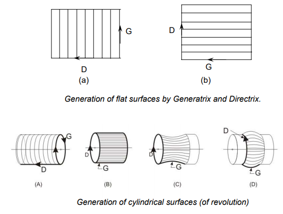
• Generation of flat surface
In Fig., a straight line called Generatrix (G) is traversed in a perpendicular direction called Directrix (D) on a flat plain, resulting in a flat surface.
• Generation of cylindrical surfaces
The principles of producing various cylindrical surfaces (of revolution) are shown in Fig,
Where a long straight cylindrical surface is obtained by traversing a circle (G) in a direction (D) parallel to the axis as shown in Fig. (a), and
a cylindrical surface of short length is obtained by traversing a straight line (G) along a circular path (D) as shown in Fig. (b)
⎯ As shown in Fig, create cylindrical surfaces by spinning a curved line (G) along a circular direction (D) (c and d).
(ii) Tool – work motions
The lines that depict the Generatrix and Directrix are normally generated by the locus of a point moving in two separate directions, and are actually obtained by tool-tip (point) motions relative to the work surface. As a result, for machining flat or curved surfaces, machine tools require relative tool work motions, which are divided into two categories:
Cutting motion (CM) and Feed motion (FM) are examples of formative motions (FM)
• Auxiliary motions such as swaying, swaying, swaying,
The motion of indexing
Adding more feed motion
a calming motion
For various machining tasks, the Generatrix and Directrix, tool and work, and their motions are frequently interlinked and in different ways. For straight turning, such linkages are commonly represented in Fig, and for shaping, in Fig.
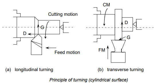
The connections in case of straight longitudinal turning shown in Fig. (a) are:
Generatrix (G) – Cutting motion (CM) – Work (W)
Directrix (D) – Feed motion (FM) – Tool (T)
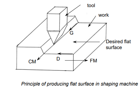
The connections in the case of making a flat surface in a shaping machine, as shown in Fig, are:
G – CM – T
D – FM – W
The Generatrix is provided by the cutting motion imparted to the cutting tool, whereas the Directrix is provided by the feed motion of the work in shaping flat surfaces.
Flat surfaces are also generated by planning machines, primarily for large works, where the work receives the cutting motion and the tool receives the feed motion, and the linkages are:
G – CM – Work
D – FM – Tool
There are four ways to gain the Generatrix and Directrix:
• Tracing (Tr) – as illustrated in Figs., the continuous line is obtained as a trace of the route of a moving point.
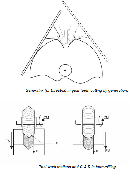
• Forming (F) – where the Generatrix is just the cutting-edge profile as shown in Fig. (c and d)
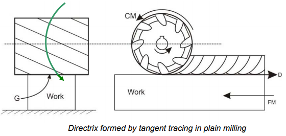
• Tangent Tracing (TTr) – the Directrix is taken as the tangent to the series of pathways traced by the cutting edges.
• Generation (G): In this case, the G or D is derived as a tangent envelope to the instantaneous positions of a line or surface rolling on another surface. As can be seen in Fig, gear teeth are generated by hobbing or gear shaping.
In a traditional horizontal arbour type milling machine, Fig. Depicts the tool-work motions and the corresponding Generatrix (G) and Directrix (D) while generating a flat surface with a plain or slab milling cutter. The tool work motions are linked to the G and D here.
G – x – T – F
D – FM – W – T.Tr
CM – T
G and D are independent of the cutting motion, and G is the milling cutter's line of contact with the flat work surface. Because the current cutter is shaped like a roller, G is a straight line, and the surface created is also flat. Form milling cutters will generate formed surfaces that are similar to those depicted in Fig. Below, where the ‘G' represents the tool-form.
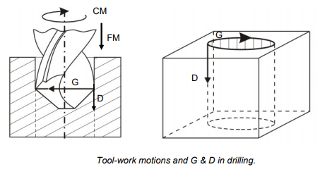
Drilling machines impart both cutting and feed motion to the cutting tool, i.e., the drill bit, while the workpiece remains stationary. Figure depicts this. G and D are linked to tool-work in the following way:
G – CM – T – Tr
D – FM – W – Tr
Boring machines are mostly used to expand and polish cylindrical holes that already exist. There are two types of boring machines:
• Jig boring machine, for example, is a vertical boring machine with a low or medium duty and high precision.
• Medium or heavy-duty horizontal axis boring machine
Vertical boring and drilling have the same tool-work motions and G and D. The feed motion is transmitted to the work in a horizontal boring machine to provide the Directrix via Tracing.
(iii) Machine tool drives
Machine tools are powered by electric motors and utilise mechanisms such as belt-pulleys, gears, and other mechanisms to achieve the desired tool-work motions. Hydraulic drive is also used in some machine tools to enable tool-work motions.
To enable • Machining various duties, machine tools require a wide range of cutting speed and feed rate (material and size)
• Using a variety of cutting tools (material, geometry and size)
• Various machining operations in lathes, such as high-speed turning and thread cutting
• Desired level of surface finish
It's possible that machine tool drivers are
o Drive-by-wire
o Drive with no steps
Stepped drives are widely used in traditional machine tools with a limited number of speeds and feeds, preferably in the G.P. (Geometric Progression) series. Modern CNC machine tools, on the other hand, are equipped with stepless drives that allow for optimal selection and flexible automatic control of speeds and feeds.
Gear boxes or cone pulleys (old technology) are used in conjunction with the power supply to achieve stepped drive. The most common method of achieving stepless driving is to
• AC or DC motors with variable speeds
• Servomotors or stepper motors
• Hydraulic power pack hydraulic power pack hydraulic power pack
2.3.2 Speed transmission from motor to spindle:
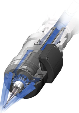
Auxiliary high-speed spindles have several benefits. They allow a traditional machine tool to reach the higher rpms needed to efficiently use small-diameter tools for semi-finishing and finishing operations. This increases a machine's flexibility while lowering energy consumption and wear and tear on the main spindle. Taking high-speed machining passes can also help you achieve faster cycle times and longer tool life.
Electric, air turbine, and mechanical “speeder” systems are all common forms of high-speed spindles. Colibri Spindles, an Israeli spindle inventor and producer, has developed a new version that rotates the auxiliary spindle using the machine's through-spindle coolant delivery system. The IMC Group's coolant-pressure-driven high-speed spindles are well-suited for tasks including milling, drilling, engraving, chamfering, thread milling, and grinding that need small-diameter tools. Iscar and Ingersoll, both part of the IMC Group, sell the spindles in North America under the names "Spinjet" and "Typhoon," respectively.
Coolant pressure powering the spindle, according to Colibri, overcomes a number of inflexibilities found in other types of high-speed spindles while also lowering operational expenses. There are 20-, 30-, and 40-bar (290-, 435-, and 580-psi) Spinjet/Typhoon spindle types available. The 20-bar spindles spin at 20,000 rpm, the 30-bar spindles at 30,000 or 40,000 rpm, and the 40-bar spindles at 40,000 or 50,000 rpm. According to the business, adjusting machining settings to these higher spindle speeds can help companies cut machining time by up to 70%.
When not in use, the small high-speed spindles can be kept in the ATC magazine of a machine and installed in the main spindle like any other tool. They may be used with ER 32 shanks, cylindrical shanks, HSK A63, CAT 40, BT30 and 40, and Capto C5 and C6 spindle connections, among others (ISO 26623-1). An ER 32 collet chuck connects the spindles to the toolholder bodies, and an ER 11 collet chuck with a maximum tool shank diameter of 0.236 inch connects the cutting tools to the spindles. For 20,000 rpm, tool diameters of 0.0787 to 0.1378 inch, 0.0394 to 0.0984 inch for 30,000 rpm, and 0.0078 to 0.0591 inch for 40,000 rpm are recommended.
Colibri recommends calculating the ratio of the auxiliary spindle speed to the original spindle speed and multiplying it by the original feed rate to establish an approximate new feed rate for an existing operation being shifted to high speed. For example, if the current operation employed an 8,000-rpm spindle and a 6.3-ipm feed rate, the new feed rate calculation utilising a 30,000-rpm spindle would be:
6.3 ipm = 23.6 ipm (30,000/8,000)
A small display that links wirelessly to the spindle via Bluetooth allows for real-time spindle speed monitoring. The display can track the speeds of up to 127 spindles on a single machine tool.
The spindles are compatible with new DMG MORI equipment and have been designed to work with SolidCAM's iMachining software. SolidCAM created models for spindle use, making it easier to establish the right cutting settings, shortening the time it takes to generate part programmes, and lowering the learning curve.
2.3.3 Speed reversal mechanism:
This invention relates to machine tools, and more specifically to a fluid under pressure reversing mechanism.
Previously, several reversing mechanisms that used a piston and cylinder mechanism to convey movement to the table were invented for controlling the reciprocating movement of machine tool tables and the like by fluid under pressure. On tables that are reciprocated at a reasonable speed, these mechanisms have proven to be rather effective. In today's industrial grinding and other machine tool operations, getting the most output per machine is critical. To obtain the most production out of a particular machine, this requirement has been partially addressed by increasing the speed of machine tool tables and other sections of the machine.
Due to the unnecessary shocks and vibrations associated with the reversal in direction of a quickly moving table, it has been discovered that the typical fluid operated reversing mechanism, as well as most mechanical mechanisms, are not adequate when used with a swiftly moving table.
The earlier systems depended on a reversing valve to reverse the direction of fluid flow at the table's end of stroke.
When the table is travelling quickly and the reverse valve is abruptly reversed to change the direction of fluid flow as well as the table's motion, the fluid is abruptly cut off on one side of the piston and allowed to enter the other. When a non-compressible fluid is abruptly cut off, it causes unnecessary shocks and vibrations to be communicated to the table when it is reversed. This has a negative impact on the machine functioning because the shocks and vibrations are conveyed to the work surface, causing chatter marks.
One of the objectives of this invention is to create a fluid-controlled mechanism for reciprocating the table at a high rate so that the table can be reversed in direction with ease and with little shocks and vibrations.
Another purpose of this invention is to create an appropriate valve system that allows the table's speed to be gradually reduced prior to 50 reversals, allowing for easy table stopping.
Another purpose of this invention is to provide an automatic fluid pressure-controlled system for reversing the movement of the table at the end of its stroke in such a way that the movement of the table is gradually retarded prior to reversal and then accelerated to its usual pace.
It is also an object to offer a manually operable mechanism that allows the operator to reverse the direction of movement of the table at any time throughout its trip without causing unnecessary shocks and vibrations, and cause the table to reverse at a specified place.
Another purpose of this invention is to provide adequate adjustments for the throttle valve mechanism so that the table's usual speed can be modified, as well as the extent of the throttling action during the reversing time.
A mechanism has been depicted in the pictures that reveals one embodiment of the invention. It should be recognised that the applicant does not want his invention to be confined to this specific embodiment, but rather that his invention encompasses any mechanism that embodies the subject matter of the claims attached hereto. Similar reference numerals represent similar sections in the drawings: Fig. Is a fragmentary front elevation of a machine tool embodying this invention, with parts broken away and shown in section to more clearly illustrate the construction; Fig. Is a sectional view through the valve mechanism taken approximately on the line 2-2 of Fig.; Fig. Is an enlarged fragmentary sectional view taken through the machine's base approximately on the line 3-3 of Fig; Fig. Is a sectional view through the valve mechanism taken approximately on the As seen in Figs, Fig. Shows a diagrammatic picture of the hydraulic system, showing the valves in position as the table begins to move to the left.
This innovation entails a fluid-operated system that can reciprocate a machine table at a high rate while allowing for shocks and vibrations to occur during the reversal of travel direction. A valve mechanism is provided that is automatically operated to control the entrance of fluid to each end of said mechanism, causing the table to reverse direction of travel at the desired location. A throttling device works in tandem with the reversing valve to limit the fluid entering and leaving the system, making reversal easier to initiate and stop.
This mechanism has a throttle valve that regulates the table's usual speed while also allowing it to be progressively closed prior to reverse and gradually opened after reverse to delay and accelerate the table's movement during the reversal time for easy stopping and starting. The throttle valve is configured to control the exhaust of fluid from the cylinder while also controlling the entrance of fluid to the cylinder, causing the table to stop and reverse at a substantially predefined location at each reversal. The control mechanism of this innovation can be operated either automatically or manually to get the desired outcomes.
A machine tool is furnished with a base 10 and a reciprocable table II suited to move on the typical V-way 12 and flat-way 13 in line with this invention. A mechanism operated by fluid under pressure, such as a chamber with a member movably positioned therein for actuation by said pressure, could be used to reciprocate the table II. A cylinder chamber 15 is supported by brackets 16 bolted to the inner portion of the base 10, as shown in the drawings. A piston I is slidably positioned within the cylinder 15 and has a piston rod 18 linked to a bracket 19 that protrudes from the table II at its outer end. As a result, any movement of the piston within the cylinder is translated into corresponding movement of the table I.
A valve mechanism, which is arranged to generate a gradual retardation and acceleration of the moving portion when reversed in direction of travel, may be used to control the movement of the piston within the cylinder. A valve mechanism 20 is bolted to the front of the machine base, as indicated in the drawings. The valve mechanism 20 consists of two valves: a reversing valve 22 that controls the direction of fluid flow to and from the cylinder 15, and a throttle valve 27 that controls the speed of the table and also allows for gradual retardation and acceleration of the table movement prior to and after reversal. A reverse valve 22 is slidably positioned within the sleeve 23 in this device. The balanced piston valve 60 member 22 is equipped with a pair of pistons 24 and 25 that are used to control the flow of fluid through the valve. The throttle valve 27. Is used to control how much fluid enters and exits the system. This valve is of the same type and is made up of three pistons 28, 29, and 30 that slide within the sleeve 31 to throttle both the intake and exhaust of fluid to the reverse valve at the same time, allowing for more uniform table speed control.
To feed and operate the system, any suitable source of fluid under pressure can be used, such as a pump 32 in the base that forces fluid from a reservoir 33 in the base to the throttle valve, reversing valve, and cylinder. This element of the mechanism has merely been diagrammatically represented because it is old and well-known in the art, and so is not deemed part of the applicant's invention. Fluid enters the system through a conduit 34 and a port 35 into a chamber 36 between the throttle valve 27's pistons 28 and 29. As illustrated in the drawings, the intake port 35 may consist of a single opening or a series of openings placed around the sleeve. As shown in dotted lines in Fig. 1, the fluid under pressure travels through the chamber 36 and is forced upwards via a port 37 in the sleeve 31 into a route 38. Fluid is pumped into a chamber 41 between the pistons 24 and 25 by a port 40 in the sleeve 23. (As shown in Fig.). As shown in Fig, fluid travels through this chamber and is driven outwards through port 42 in sleeve 23, conduit 43, and port 44 into the left-hand end of cylinder 15. The fluid entering and passing through the valves in this direction pushes the piston 17 to the right, as shown in Fig, and transfers that movement to the table I via the previously stated connections.
A mechanism is provided to operate the reversing valve at the desired moment to convert it to its opposite position and therefore reverse the flow of fluid to the cylinder 15. As shown in the drawings, the reversing lever 48 is attached on a stud 49 on the front of the base 10. A stud 51 connects a link 50 to the lever 48 on a pivot. A pin 52 is slidably installed in an elongated slot 53 in the member 54 on the end of the valve 22 at the other end of the link 50. The extended gap is designed to allow the reversing lever 48 to be moved without causing the reversing valve to move.
The lever 48 is held in the proper position to control the reversing valve 22 by a load and fire mechanism. A lever 55 is pivotally mounted on a stud 56 and has a V-shaped projection 57 on its opposite end that is designed to contact a similarly shaped projection 58 on the back side of the lever 48, as shown in the drawings. The projection 57 should be held in contact with the projection 58 if the lever 55 is under tension. One end of a spring 59 is attached to a pin 60 on the lever 55, and the other end is linked to a pin 61 on the front of the machine base, as shown in the pictures. As the operator pulls the lever 48 to the right, as shown in Fig, the projection 58 interacts with the V-shaped end 57 to elevate the lever 55 and therefore increase the strain on the spring 59. This movement continues until the high point on the projection 58 passes the high point on the projection 57, at which point the spring's released tension swiftly reverses the valve 22.
The elongated slot 53 is provided so that the lever 48 can move until the high point on the projection 58 passes the high point on the projection 57 without causing the reversing valve 22 to move.
The reversing valve 22 has a stop pin 62 in the cylinder head 63 to limit the valve's movement to the right so that the pistons are suitably positioned relative to the ports in the sleeve 23. On the valve stem 22, a collar 64 is positioned to limit the valve's movement to the left, allowing the valve to be positioned similarly to the corresponding ports in the sleeve. A pair of adjustable dogs 65 and 66 are supplied to allow the lever 48 to be adjusted automatically at the desired location, and they are supported by bolts 67 and 68 with their heads 69 slidably installed in the T-slot 70 created in the front edge of the machine table. Pins 72 and 73 are supplied on the dogs 65 and 66, respectively, that are suited to touch the reversing lever 48's adjustable screws 74 and 75. '7 Assuming the table is moving in the direction of the arrow (Fig), this movement will continue until the pin 72 on the dog 65 makes contact with the screw 74 on the lever 48, pushing it to move to the right and moving the link 50 and pin 52, which is free to slide within the elongated slot 53. This movement continues until the high point on the projection 58 passes the high point on the V-shaped end 57, at which point the spring 59's released tension causes the reversing valve 22 to rapidly throw to the right, changing the direction of fluid flow to and from the cylinder 15.
While the fluid is flowing into the left-hand end of the cylinder 15 through the conduit 43 through the port 44, it is exhausting from the other end of the cylinder through a port 78 and a conduit 79 through a port 80 in sleeve 23 into a chamber 81 between the piston 25 and the cylinder head 63. The fluid then travels to the throttle valve 27 via an exhaust port 82 in sleeve 23 and a passage 83. The exhaust fluid enters the throttle valve through a port 84 in sleeve 31 and flows through a chamber 85 between pistons 29 and 30 before exiting through a port 86 in sleeve 31 and conduit 87 into the reservoir 33.
When the reversing valve 22 is moved to the right into a reverse position, the fluid passes through the throttle valve 27 in the same direction, through port 40 into the chamber 41 between the pistons 24 and 25, out through a port 80 in sleeve 23 and the conduit 79, and through port 78 into the right-hand end of cylinder 15, as shown in Fig. This action pushes the piston 17 to the left and causes the table 1 to move in the same direction. Fluid is evacuated from the left-hand end of the cylinder 15 through port 44, conduit 43, and port 42 in the sleeve 23 into a chamber 88 between the piston 24 and a cylinder head 89 while the reversing valve is in this position. The fluid is subsequently driven into the chamber 85 between the pistons 29 and 30 through a port 90 in the sleeve 31's route 83 and port 84, and subsequently exhausts through port 86 and conduit 87 to the reservoir 33.
The throttle valve is wide open in Fig. To allow maximum fluid flow through the intake and exhaust ports in order to achieve maximum speed on the work table. Both the intake and exhaust ports can be throttled to give the reciprocable table the necessary speed by modifying the position of the throttle valve 27, that is, by shifting it to the right.
A device is provided to progressively close and open the throttle valve so as to retard and accelerate the movement of the table before and after the reversing valve is changed into its reverse position, allowing for easy stopping and starting of the table during the reversal period. A bell crank lever 91 is pivoting on a stud 92 on the front of the machine base, as illustrated in the drawings. The bell crank has a follower roller 93 on one arm and an adjustable screw 94 on the other, which is positioned to engage the end of the throttle valve 27 so that any movement of the lever 91 is translated into a matching movement of the throttle valve.
A pair of cam plates 95 and 96 are provided and positioned on the dogs 65 and 66, respectively, to allow the throttle valve to be moved automatically in timed relation with the reversing valve movement. As the table II advances to the right, the cam 76 95 makes contact with the bell crank lever 91's follower roller 93 before the pin 72 makes contact with the screw 74, as shown in Fig. The cam 95 presses the roller 93 downward as the table travels to the right, rocking lever 91 and transmitting motion to the adjustable screw 94, which moves the throttle valve 27 toward the right to gradually close the throttle valve. The shape of the cams 95 and 96 can be changed to control the throttling movement. The throttle valve is gradually closed to check the flow of fluid travelling through the hydraulic system and to slow down the movement of the table II before the load and fire mechanism functions to shift the reversing valve 22 into a reverse position, as can be seen from this construction. The fluid starts flowing in the other direction through the reversing valve and cylinder when the reversing valve has shifted, which functions to move the table 11 in the opposite direction. As the table moves at its regular speed, the roller 93 rides up the face of the cam 95 and progressively opens the throttle valve, increasing the flow of fluid via the hydraulic system and speeding up the table movement. As shown in Pig. 1, the table continues to travel to the left until the follower roller 93 makes contact with the cam 96, which provides a comparable throttling action before and after the reversing valve 22 is changed into the reverse position. At each reversal of the table, the operation cycle is repeated.
A stop mechanism is ideally provided to limit the movement of the throttle valve 27 in a leftward direction, allowing the table's typical speed to be easily modified. This consists of a cam 98 rotatably mounted on the stud 99, which is operated by a lever 100, as shown in the drawings. A spring pressed plunger 101 is supplied at the lower end of the lever 100, the specifics of which have not been depicted because they are old and well known in the art. This plunger 101 is designed to fit into the arcuate member 103's notches 102. It should be obvious from this design that pushing the lever 100 to the right causes the cam 98 to revolve and move the throttling valve. This adjustment allows the throttling valve to be positioned to give the table 11 the required usual speed.
At the end of the valve 27, a spring 104 is used to keep the valve stem in contact with the adjustable screw 94 and the head of the screw 94 in operative engagement with the cam 98. The cam 98 is set to the desired position to give the table the right speed, and it is then left in that position.
During the reversal time, it may be advantageous to adjust the degree of throttling movement of the valve 27. This is when the adjustable screw 94 comes in handy. The position of the bell crank lever 91 is changed by rotating this screw, the ends of which are fixed relative to the cam 98, to adjust the point at which the roller 93 contacts the cams 95 and 96 relative to the pins 72 and 73 striking the screws 74 and 75 on the reversing lever 48. The amount of gradual slowing down of the table prior to the throwing of the reversing valve can be determined by this adjustment, allowing the operator to achieve the appropriate simple stopping and starting action for the table. It may be useful to control the movement of the table manually in some grinding or other machine tool operations so that it can be reversed at any point during the regular stroke of the table without waiting for the dogs to act and automatically reverse the table. A proper manual control is offered to this end. Augmenting the system previously described so that when the operator swings the reversing lever 48 by hand, the throttle valve 27 can be closed S gradually. The lever 55 is preferably shaped like a bell crank lever with a short arm' 105 and an adjustable screw 106 designed to make contact with a lever 107 that is part of the bell crank lever 91. As the operator moves the reversing lever 48 to the right, as shown in Fig, the projection 58 on the lever interacts with the V-shaped end 57 of the lever 55 to rock the lever about its stud 56. This movement, which is controlled by the lever 105 and screw 106, causes the lever 107 and bell crank 91 to swing to the right, allowing the fluid travelling through the valve to be throttled. Because the throttle valve 27 is triggered by the manual movement of the reversing lever 48 to slow down the movement of the table I 1 before the reversing valve is changed, the operator can reverse the table at any time throughout its stroke without creating undue shocks and vibration.
In order to reciprocate the table, the operator opens the valve that controls the fluid pressure line or begins the pump, which admits fluid through the throttle valve 27 and the reversing valve 22. The operator then adjusts the position of the throttle valve 27 with the lever 100 to get the desired table speed for the operation.
After this adjustment, the operator can modify the amount of throttling movement at reversal by adjusting the position of the screw 94 relative to the bell crank lever 91. This will give the desired retarding and accelerating action shortly before and after the reversing valve 22 is changed. Following these modifications, the dogs 65 and 66 can be moved around the table 11 to achieve the required stroke length and position the table in relation to the work. To alter the time between the cam 95 striking the roller 93 and the pin 72 striking the screw 74, the screws 74 and 75 can be adjusted in relation to the lever 48.
The operator can alter the amount of movement of the table between the start of the throttle action and the shifting of the reverse valve with this adjustment.
After having described the invention, the following is claimed as new and sought by Letters Patent:
1. A reversing mechanism for a machine tool table comprising a fluid pressure actuated motor connected to move the table, a source of fluid pressure, means including a reversing valve for admitting and exhausting fluid under pressure to said motor, and a throttle valve controlling the exhaust of flu
2. A reversing mechanism for machine tool tables comprising a fluid chamber, a member movably mounted within said chamber and operatively connected to reciprocate the table, and a reversing mechanism comprising a valve operatively connected to admit fluid under pressure to either end of said chamber, and a throttle valve arranged to simultaneously throttle the intake and exhaust of fluid to and from said chamber.
3. A reversing mechanism for machine tool tables comprising a cylinder and piston connected to reciprocate said table, and a reversing mechanism comprising a valve operatively connected to admit fluid under pressure to either I end of said cylinder, and a throttle valve arranged to throttle the inflow and exhaust of fluid to and from the reversing valve at the same time.
4. A reciprocating mechanism for machine tool tables comprising a cylinder and piston arranged to reciprocate said table, a reversing mechanism comprising a valve operatively connected to admit fluid under pressure to either end of said cylinder, a throttle valve controlling the exhaust of fluid from the cylinder, and means to adjust the throttle valve to control the flow of fluid and thus produce a reversing mechanism comprising a valve operatively connected to admit fluid under pressure to either end of said cylinder.
5. A reversing mechanism for machine tool tables comprising a cylinder and piston arranged to reciprocate said table, a pump to force fluid under pressure into said cylinder, a fluid reservoir, a reversing mechanism comprising a valve operatively connected to admit fluid under pressure to either end of said cylinder, a throttle valve arranged to simultaneously throttle the inflow and exhaust of fluid, and a reversing mechanism comprising a valve operatively connected to admit fluid under pressure
6. A reversing mechanism for machine tool tables comprising a cylinder and piston arranged to reciprocate said table, a source of fluid under pressure, a reversing mechanism comprising a 95 reversing valve operatively connected to admit fluid under pressure to either end of said cylinder, a throttle valve arranged to simultaneously throttle the inflow and exhaust of fluid, and means to adjust the position of said cylinder
7. A reversing mechanism for machine tool tables, comprising a cylinder and piston arranged to reciprocate said table, a source of fluid under pressure, a reversing mechanism comprising a valve actuated by said table to change the direction of flow of fluid under pressure to said cylinder, a throttle valve arranged to control the exhaust of fluid from the reversing valve, and means actuated by movement
8. A machine tool table reversing mechanism comprising a cylinder and piston arranged 10 to reciprocate said table, a pump to force fluid under pressure to said cylinder, a fluid reservoir, and a reversing mechanism comprising a valve to change the direction of flow of fluid under pressure to said cylinder, and a lever to actuate said valve. S5 adjustable dogs on said table to actuate said lever, a throttle valve arranged to control the flow of fluid through the reversing valve, means to adjust the position of said throttle valve to control the table's normal speed, and means actuated by said table to gradually close said throttle valve prior to reversal to retard the table's speed.
9. A reversing mechanism for machine tool tables comprising a cylinder and piston arranged to reciprocate said table, a pump to force fluid under pressure into said cylinder, a fluid reservoir, a reversing mechanism comprising a valve operatively connected to permit the flow of fluid under pressure to either end of said cylinder, and a throttle valve to control the flow of fluid through said reversing mechanism.
10. A reversing mechanism for machine tool tables comprising a cylinder and piston arranged to reciprocate said table, a pump to force fluid under pressure to said cylinder, a fluid reservoir, a reversing mechanism comprising a valve to change the direction of flow of fluid under pressure to said cylinder, a throttle valve arranged to control the flow of fluid through the reversing valve and a reversing mechanism comprising a valve to change the direction of flow of fluid through
11. A reversing mechanism for machine tool tables comprising a cylinder and piston arranged to reciprocate said table, a source of fluid under pressure, a reversing mechanism comprising a valve operatively connected to admit fluid under pressure to either end of said cylinder, a throttle valve arranged to control the flow of fluid through the reversing valve, and manual means to adjust the position of the reversing valve
12. A reversing mechanism for machine tool tables comprising a cylinder and piston arranged to reciprocate said table, a source of fluid pressure, a reversing mechanism comprising a valve operatively connected to admit fluid to either end of the cylinder, a throttle valve to control the flow of fluid through the reversing valve, and means to adjust the position of said throttle valve to regulate the flow of fluid through the reversing valve, and means to adjust the position of said throttle valve
13. A reversing mechanism for machine tool tables comprising a cylinder and piston arranged to reciprocate said table, a pump to force fluid under pressure to said cylinder, a fluid reservoir, and a reversing mechanism comprising a valve arranged to control the flow of fluid under pressure to either end of said cylinder, a throttle valve to control the flow of fluid through said reverse valve, and adjustable.
14. A reversing mechanism for machine tool tables comprising a cylinder and piston arranged to reciprocate said table, means including a pump to force fluid under pressure to said cylinder, a reversing mechanism comprising a valve to change the direction of flow of fluid under pressure to said cylinder, means comprising a throttle valve arranged to control the flow of fluid through the reversing valve, means comprising a throttle valve arranged to control the flow of fluid through the reversing
15. A reversing mechanism for machine tool tables comprising a fluid chamber, a member movably mounted within said chamber and operatively connected to reciprocate the table, a reversing mechanism comprising a valve operatively connected to admit fluid under pressure to either end of said chamber, and a throttle valve arranged to throttle the intake and exhaust of fluid to and from the r
2.3.4 Feed motion:
The train of mechanisms that moves the part of a machine that produces the feed directly.
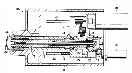
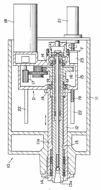
This invention relates to machine tools in general, and in particular to those with a spindle on which multiple cutting tools, arbours, and other attachments can be installed interchangeable. The innovation is more specifically a spindle head with a mechanism for feeding the spindle against work. Although no needless limits are envisaged, the spindle head according to the invention is well suited for use in boring machines.
Boring machine spindles are fed lengthwise out of the spindle head against the work. For a study of the traditional spindle feed mechanism, consider a horizontal boring and milling machine. The boring spindle has been received into a hollow milling spindle and is keyed or splined to the milling spindle for axial sliding movement. The boring spindle has been attached to a feed mechanism, such as a hydraulic actuator or a feed screw, for axially driving it with regard to the milling spindle. The milling spindle is rotated by a gear train connected to the boring spindle's drive motor.
The boring spindle was therefore fed out of the milling spindle during machining, according to the previous art. As a result, when the boring spindle was extended out of the milling spindle, it was supported effectively in a cantilever form. Of course, such cantilever support of the boring spindle is disagreeable since it is subjected to larger bending loads during machining due to the cutting tool placed to its distal end. The outcome has been easy deflection of the boring spindle under load, as well as subsequent cutting tool vibration. Because the boring spindle is easily deflected under its own weight, there are restrictions on the size and weight of cutting tools and attachments that can be placed to it.
The boring spindle has been free to experience axial deformation since it is slidable axially with regard to the milling spindle. This has caused an additional annoyance. The boring spindle has proved sensitive to thermal deflection as heat builds up during machining, reducing machining accuracy.
Brief Description of the Drawing
A spindle head for a horizontal boring machine constructed in accordance with the invention is shown in axial section in the accompanying drawing.
2.4.1 Type of work holding devices being used on lathe:
Work holding devices on a lathe
The lathe, as we all know, is one of the oldest and most important machine tools. This machine tool has a wide range of uses. As a result, it should be held tightly and securely to allow for easy machining of the work piece. For this aim, a variety of accessories are employed to make it easier to handle the work piece.
Some of the work-holding devices include the following:
1) Carriers and catch plates
2) Face plates
3) Angle plates
4) Mandrels
5) Rests
1. Carriers and catch plates
Catch plates

Carries
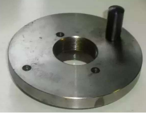
These are typically used to drive the work piece when it is held between two centres, such as the head stock and tail stock. Driving dogs are another name for carriers. Setscrews are used to secure them to the work piece. The catch plates, on the other hand, are fixed to the headstock.
2. Face plates
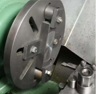
Faceplates are used to hold work items that are too large for centres or chucks to hold. The faceplates are made in a relatively straightforward manner. It has a centre bore and plain and radial slots through the plate to help hold the work piece in place. The radius of the centre bore is the same as the radius of the lathe's spindle. The simple and radial slots provide a stable base for T-bolts and clamps to hold the works in place.
3. Angle plates
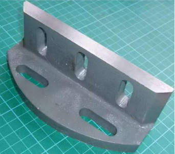
These are used in conjunction with faceplates to keep the work piece horizontal, i.e., perpendicular to the tool. Angle plates feature two precisely machined faces on which holes are provided for simple clamping of the work piece.
4. Mandrels
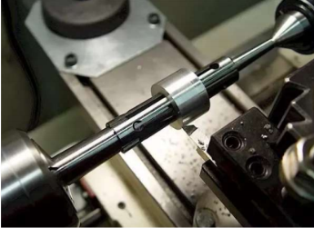
This sort of work holding device is used to hold a previously drilled or bored hole in place while machining the outer surface. Between the centres, the work is loaded onto the mandrels. The mandrels' ends are a fraction of an inch narrower than the original diameter. This is done to ensure that the mandrel is properly gripped in the chuck or other holding device. In most cases, ordinary carbon steel is utilised to make the mandrels. Mandrels come in a variety of shapes and sizes. Mandrels come in a variety of shapes and sizes.
1) Plain mandrels
2) Step mandrels
3) Collar mandrels
4) Screwed mandrels
5) Cone mandrels
6) Gang mandrels
7) Expansion mandrels
Plain mandrel
This sort of mandrel has a wide range of uses in shops that need to produce similar components. These mandrels have a tapered curvature to their bodies. The tapped diameter varies from 1 to 2 mm, and the length ranges from 55mm to 430mm. The tapper is included to make high-end gripping for holding the work piece easier.
Step mandrel
A particular form of mandrel that allows for speedier processing by holding a variety of job sizes without having to replace the mandrel. These mandrels are commonly seen in repair shops and are used to turn collars, washers, and odd-sized projects.
Collar mandrel
A collar mandrel has a fixed collar arrangement that can be larger than the standard 100mm. This style of construction is a way of getting the most out of the materials you're using.
Screwed mandrels
One side of these mandrels has a thread cut carved on it, as well as a collar. Screwed mandrels are the name for this type of mandrel. When working with work components that have internal threads, screwed mandrels are employed. The size of the threads to be engraved on the screwed mandrels depends on the type of work piece, which is going to fit over it.
Cone mandrel
A cone-shaped component is affixed to one of the mandrels in cone mandrels. The mandrel can handle a variety of work parts with various interior cross-sectional diameters thanks to this configuration. Fixing a nut at the other end of the work piece to the mandrel tightens the hold on the work piece. The interior surface polish of the work piece, as well as the cone form of the mandrel, may be damaged if the work piece is too tightly fitted over the cone.
Gang mandrel
Some optimizers generate gang mandrels in order to reduce the amount of material used. This sort of mandrel can be used to machine a variety of work components with different diameters. The gang mandrels are made up of a permanent collar on one end and removable mandrels on the other, which are held in place by threads engraved on both the mandrel and the inside surface of a hollow mandrel. By removing and fastening several collars over the thread, this mandrel may be used to machine various diameter components. The friction between the walls of the collar and the sidewalls of the work piece is sufficient to hold the work piece tightly, allowing for high-quality machining.
Expansion mandrel
This is a unique form of mandrel with a tapered pin in the centre. Over this tapered pin a sleeve is arranged when this sleeve is moved over it form one corner to other the size increases or decreases. When a variety of diameter components must be held without difficulty, this style of mandrel is ideal.
Chucks
A chuck is a tool for holding work in place. It's used to hold work on a lathe machine that has a long length and a tiny diameter, as well as projects that can't fit between the centres, such as the head stock and tail stock centres. When mounting a non-axis symmetrical object over the lathe, a chuck is also used. The most popular work holding devices are chucks. These are screwed directly to the lathe's spindle and secured with a rear plate. In general, there are several varieties of chucks, each with its own significance and applications.
Types of chucks
• Four jaw chuck or independent chuck
• Three jaw chuck or self-centering chuck
• Air or hydraulic operated chuck
• Magnetic chuck
• Collet chuck
• Combination chuck
• Drill chuck
Four jaws or independent chuck
This chuck, as the name implies, has four jaws for retaining the work, each of which may move independently.
Advantages
a. Any sort of work item can be easily handled
b. Because four jaws are used, a strong grasp is feasible.
Disadvantages
a. The process of centering is a little tough.
b. Semi-skilled work is necessary.
Three jaw chuck (or) self centering chuck
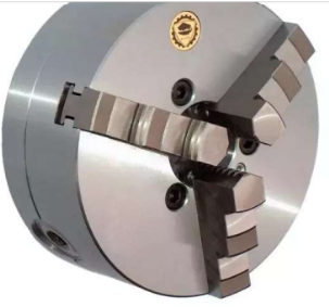
Three jaw chucks, also known as self-centering chucks, have three jaws for gripping the work piece, and if one jaw moves, the other jaws move by the same amount. This mechanism is created by engaging pinions that mesh with the teeth cut into the chuck's underside. This chuck is also referred to as
universal chuck
Advantages
a. No centering is required because all jaws move at the same time.
b. Mounting and unmounting the work piece takes less time.
Disadvantages
a. The grip isn't as strong as it could be because only three occupations are available.
b. All type of jobs cannot be mounted on these chucks, as they are useful in machining only axis symmetrical objects
Combinational chuck
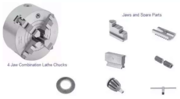
It's a mixture of three-jaw and four-jaw chucks, as the name implies. It functions as a self-centering and autonomous chuck at the same time. This is accomplished by activating a scroll disc on the jaws' rear.
Magnetic chuck
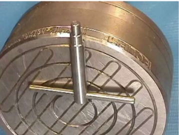
The work item is held in this chuck by magnetic force.
Advantages
• Work pieces that cannot be damaged by chuck jaws can be efficiently machined using this chuck.
• If the work to be held is very small and cannot be held by the above three chucks, then this chuck can be used.
Disadvantages
a. It is impossible to hold all types of work.
b. The size of the job has an impact on the holding's efficiency.
c. It cannot hold all types of materials because it is based on magnetic properties. Only magnetic materials can be held.
Collet chuck
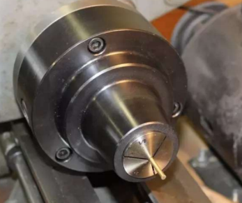
When the work to be held is exceedingly lengthy, this sort of chuck is employed.
Air or hydraulic operated chuck
Because it is powered by hydraulic or air energy, it is also known as a pneumatic chuck. Due to the pressure generated in the cylinder, this chuck retains the work piece.
Drill chuck
This chuck is used for holding the tool in the drilling machines. This also plays a role in holding taper shanks on a lathe for easy machining of the job on which holes are to be drilled.
Because it is powered by hydraulic or air energy, it is also known as a pneumatic chuck. Due to the pressure generated in the cylinder, this chuck retains the work piece.
Rests
Rest is a work holding device that is used to hold work pieces that are quite long in length. In general, when a long piece is to be held it may have directly held then there arises deflection in the work piece due its own weight. Rests of various forms are used to avoid deflection in the work piece. Some of the rests that are now being used are:
1) Steady rest
2) Follower rest
2.4.2 Tools and Holding Devices:
Tools and Holding Devices Tools | |||
Word | Meaning | Context | More Information |
"A" - clamp | "A" shaped clamping device. | 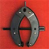 "A" - clamp |
These clamps are adaptable and simple to operate. They have a cam-driven motion. They keep workpieces from twisting. |
Angle plate | Angle plates are used in layout work and to position up work pieces for drilling or milling at a 90-degree angle to the table. | 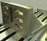 Angle plates are a common layout accessory. | 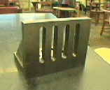 Angle plate / layout |
"C" - clamp | "C" shaped clamping device. | 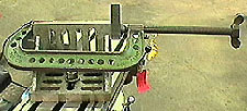 Clamping devices are used by the operator for safe handling and ease of operation. | Workpieces can be secured to angle plates for layout operations using "C" - clamps. Clamps in the shape of a "C" are available in sizes ranging from 1 to 16 inches. |
Center punch | Prick punch holes are enlarged using a centre punch.
|  Center punch has an included point angle of 90 degrees. |
Center punches should not be used in place of a layout punch to mark the workpiece prior to machining operations such as drilling. |
Dividers | Dividers are used to scribe evenly spaced divisions by transferring distances straight from the rule to the work. Arcs and circles are also scribed with them. | 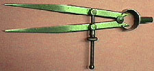 Dividers are available in various sizes. | Dividers are normally put up according to a set of guidelines. It has two sharp tips, similar to a pencil compass. Sharpness can be achieved by lightly honing the points. |
Drill vise | Drill vise is a holding device used for clamping most workpieces while drilling. | 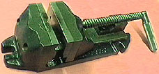 One of the most commonly used work-holding devices is also called a drill press vise. |
For parallel work, vises are the quickest and most effective form of setup. Available in many sizes. |
Gooseneck clamp | A gooseneck is a mechanism that secures a work piece to a table. | 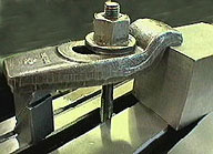 The measuring surfaces are lapped and polished to 200 millionths of an inch. | The top of the clamping bolt can be positioned below the surface to be machined with the gooseneck clamp. |
Hermaphrodite caliper | The Hermaphrodite calliper locates and scribes parallel lines in a work piece. |  The hermaphrodite caliper can also be used to lay out the center of round stock. | Available in a variety of sizes. Inside lines are reversible. It has two legs, one with a sharp point and the other with a hook. |
Kant-Twist clamp | The Kant-Twist clamp is a heavy-duty clamp. | 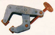 Clamping devices are used for safe handling and ease of operation. | Kant-Twist clamps are about half the weight of comparable C-clamps. They outperform traditional C-clamps. They do away with distortion and twisting. |
Laying out | The procedure of transferring reference marks from a blueprint to the work item is known as laying out or lay-out. | The data that is measured and transmitted must be precise. A mistake in the layout will result in a mistake in the final product. | Accurate workmanship necessitates the ability to measure precisely with the appropriate equipment and gauges. |
Parallel clamp | A parallel clamp, also known as a machinist or toolmakers' clamp, is a low-reach heavy-duty clamping device. | 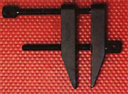 Toolmakers' parallel clamp | Clamping devices are utilised for easy operation and safe handling. Clamp that is both stronger and smaller than a C-clamp. |
Prick punch | Prick punches are used to mark the position of holes softly. |  The prick punch has an included point angle of 30 degree. |
The only punch that should be used in layout is the prick punch. It's utilised to keep a layout mark in place while causing the least amount of harm to the work item. |
Scriber | A scriber is a pointed, sharp tool used to draw straight lines. |  A scriber is used with a square rule or straight-edge for drawing straight lines. This is particularly important when laying out. | For added safety, the pocket scriber's handle can be inverted. The point can be carbide or hardened steel. |
Step blocks | The work piece is supported by step blocks. |  The height of the work piece determines the correct step block on which a clamp can be placed to secure the work piece. | Clamping aids such as step blocks are quite beneficial. They're utilised with gooseneck clamps, "U" clamps, and strap clamps. |
T-bolt | The T-shaped head is used to secure work to the table. | 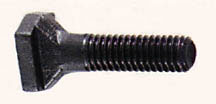 T-slot bolt | T-bolts are utilised on the tables and faceplates of milling machines. T-bolt heads frequently fit into slots on drill press tables. |
Trammel | Trammel scribes circles or arcs that are too large for dividers by measuring between two points. | 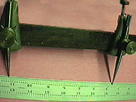 Trammel | Trammel points can be clamped directly by rule graduations or attached to a bar and set to circle dimensions. |
Transfer punch | A transfer punch is a tool that is used to transfer holes ranging in diameter from 1/16th to 2 inches in diameter. | 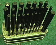 Transfer punch set | Any hole shape-round rectangle, square, elongated, or tear-shaped materials up to 2 inches or 50 mm thick-can be punched using a transfer punch. |
"U" - clamp | A device in the shape of a "U" that is used to hold a work piece in place. It has a never-ending slot. | 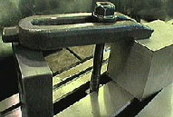 Clamping devices are used for safe handling and ease of operation. | The "U" - clamp has the benefit of being able to be removed without removing the nut from the T-bolt. |
V-blocks | V-blocks are used to retain round stock while working on layouts. | 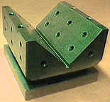 Round work pieces can be securely fastened in a set of V-blocks. |  To prevent the shaft from bending under cutting pressure a V-block and screw jack can be used to support the shaft. |
Key takeaways:
• Work holding is a combination of spatial location and positive and/or frictional constraint that keeps the workpiece in place and prevents it from being displaced by cutting forces and its own weight.
• The term "work holding" in CNC milling refers to all of the components needed to keep the work secure when milling the block of material. It begins off simple when handling pieces with square edges, but it gets more challenging as the pieces get more complex, and it completely changes when it comes to mass production.
2.5.1 Types of Metal Cutting Machine Tools:
In the manufacturing business, machine tools play a critical role. These are the shears, cuts, drills, punches, grinds, and presses that are used in machining. Machine tools, in general, are power-driven metal cutting or forming equipment that are used to reduce the size and shape of a work piece by removing undesired portions, controlling electrical machinery processes, and pressing, sealing, drawing, or shearing. Manual or automatic control is used to operate the machine tools. Metal cutting machine tools, metal forming machine tools, and other machine tools are among the many types of machine tools available. Lathe, drilling machine, milling machine, boring machine, grinding machine, and machining centre are examples of metal cutting machines. The machine tools are known as "mother machines" because they allow other machines to function. The various types of metal cutting machine tools will be discussed in this article.
METAL CUTTING MACHINE TOOLS
A) LATHE
The lathe is a metal-cutting machine tool that rotates the workpiece around an axis of rotation to produce a symmetrical item around that axis. Undercutting, grooving, knurling, plain and step turning, facing, threading, drilling, parting, cutting, shaping, chamfering, reaming, boring, filing and polishing, and taper turning are all done with lathe cutting tools. In lathe machine work, different types of lathes cutting tools are required for different processes. They are as follows:
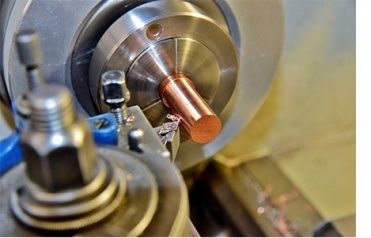
1) According to the method of using the tool
• Cutting tool for threads
• Facing tool for faces
• Boring tool for holes
• A tool for turning
• Cutting tool for internal threads
• A tool for undercutting
• Tool for chamfering
• Forming device
• Anti-boring tool
• A parting-off tool is a tool that is used to separate two pieces of
• Grooving instrument
2) According to the method of applying feed
• Round Nose
• Left-hand tool
• Right-hand tool
B) DRILLING MACHINE
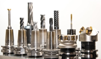
Drilling is one of the most difficult machining procedures. The key characteristic of a drilling machine that separates it from other machining operations is the combined cutting and metal extrusion at the chisel edge in the middle of the drill. The drilling machine, also known as a drill press, is an ubiquitous and important machine used in industry for making and completing holes in a worksite. Reaming, boring, drilling, tapping, lapping, counterboring, countersinking, grinding, spot facing, and trepanning are some of the activities that a drilling machine can do. A wide range of drilling machines are available, ranging from simple portable equipment to extremely complicated automatic and numerically controlled equipment. They are as follows:
• Drilling machine on wheels
• Drilling equipment with high sensitivity
• Drilling equipment that stands upright
• Machine for radial drilling
• Machine for gang drilling
• Machine with many spindles
• Drilling machine that works automatically
• Drilling machine for deep holes
C) MILLING MACHINE
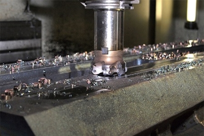
This is a type of metal cutting tool in which the workpiece is fed against a rotating multipoint cutter, which slices the metal. The cutter rotates at a very high speed and slices the metal at a very quick pace because of the many cutting blades. This metal cutting machine can operate with one or more cutters at the same time. As a result, one of the most significant machines in the workshop is the milling machine. In this machine, all operations may be carried out with excellent precision. In comparison to the lathe, planner, and shaper machines, this milling machine has a high metal removal rate. It offers a smoother surface finish and is more precise. And it is for this reason that a milling machine is often used in manufacturing. Gear milling, form milling, side milling, profile milling, plain milling, face milling, gang milling, end milling, saw milling, milling keyways, grooves, and slots, straddle milling, angular milling, thread milling, cam milling, and helical milling are examples of milling machine processes. The following are the several types of milling machines:
1) Column and knee type
• Horizontal or plain milling machine
• Hand milling machine
• Milling machine (vertical)
• Milling machine (universal)
• Milling machine with omniversal capabilities
2) Manufacturing type or fixed bed type
• Milling machine (simplex)
• Milling machine (duplex)
• Milling machine (triplex)
3) Planar type milling machine
4) Special type
• Milling machine with a rotary table
• Milling machine with a drum
• Milling machine with a profile
• Milling machine with a planetary spindle
• Milling machine with a tracer
• Milling machine for panographs
• Milling machine (NC/CNC)
D) BORING MACHINE
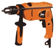
Boring, also known as internal turning, is a technique for increasing the inside diameter of a hole. We can achieve three things with boring: size, straightness, and concentricity. Boring includes the turning actions that occur in conjunction with exterior turning. Internal turning or drilling, on the other hand, are constrained by the hole diameter and length of the work piece. Boring operations can be carried out on a variety of machines, including lathes, milling machines, and machining centres, in addition to boring machines. Boring machines, like most other machine tools, are categorised as horizontal, vertical, precision, or jig boring machines.
1) Horizontal boring machines
• Horizontal boring machine with a table
• Horizontal boring machine for the floor
• Horizontal boring machine of the planner type
• Boring machine with multiple heads
2) Vertical boring machines
• Standard vertical boring machine
• Vertical turret lathe
3) Precision boring machine
4) Jig boring machine
• Type of vertical milling machine
• Type of planer
E) GRINDING MACHINE
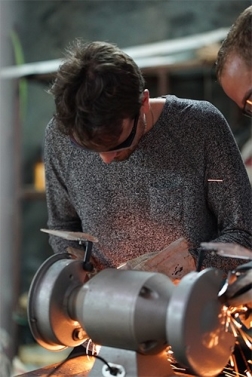
Lathes, standard milling machines, and shapers were once used for abrasive machining or grinding. Various types of grinding machines are currently used to carry out the processes. Grinding machines have evolved in construction, rigidity, design, and application significantly more in the recent decade than any other common machine tool in the manufacturing industry. There are five various types of grinding machines, such as -
1) Surface grinders
• Reciprocating table with horizontal spindle
• Rotary table with horizontal spindle
• Reciprocating table with vertical spindle
• Rotary table with vertical spindle
2) Internal grinders
3) Cylindrical grinders
4) Centerless grinders
5) Special grinders
• Jig grinding machines
• Tool and cutter grinders
• Machines for thread grinding
F) MACHINING CENTER
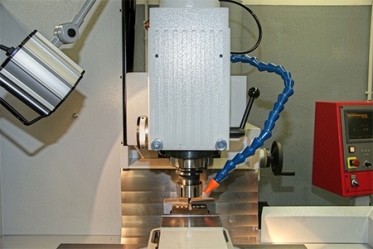
A machining centre consists of an automatic tool changer and a table that secures the workpiece in place and is found in practically every CNC milling and drilling machine. It may seem unusual that the tool on a machining centre revolves, but the work does not, as it is mostly static. The orientation of the spindle is the most basic distinguishing feature of a machining centre. This machining centre, which functions as an advanced computer-controlled machine, performs a variety of machining operations on multiple orientations and surfaces of a workpiece. Machining centres come in a variety of styles. There are three basic types:
• Horizontal spindle
• Vertical spindle
• Machining centre with five axes
2.5.2 Types of surfaces generated
Axially generated surface
The resulting surface finish will be shaped like the bottom of the insert. Cusps are created by using a corner radius (RE) insert. The radius and feed determine the size of the cusps.
A flat surface can be created using inserts with a parallel land (BS). The milling surface finish is created by the insert with the lowest position, which is determined by the cutter's axial tolerance and run-out.
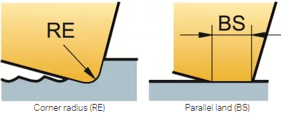
To generate the best milling surface finish, it is important to ensure that the feed per revolution (fn = fz x zn) is less than 80% of BS.
The number of teeth and feed per revolution increase as cutter diameter grows (especially for extremely close pitch cutters), necessitating a larger BS. The axial run-out of the cutter will impact the surface finish as soon as the feed per revolution exceeds the width of this land.
For best milling surface finish, use:
- Wiper inserts or milling inserts with BS at least 25% larger than fn
- Cermet inserts for a mirror finish
- Cutting fluid to avoid smearing
Wiper inserts
Finishing in bigger diameters is possible with a wiper, or lengthy parallel land. The wiper is placed below the conventional inserts to ensure that the surface is generated by this insert. The maximum fn should not exceed 80% of the BS.

Round inserts
Although round inserts and inserts with a big corner radius are incredibly prolific, they do not provide a high-quality surface. The worse the surface polish, the greater the cutter diameter.
Radially generated surface
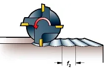
A radial surface is created when an end mill, shoulder mill, or side and face mill cutter is used. The side of the tool that generates the profile on a radial produced surface is the side of the tool that generates the profile.
Each tooth generates a cusp (h), the width of which is defined by the relationship between the cutter diameter and fz, and the depth of which is dictated by the relationship between the cutter diameter and fz. The cusp created theoretically has a small size.
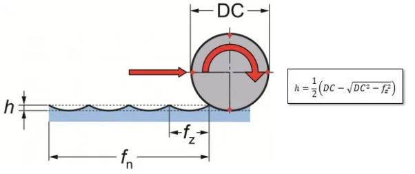
Sculptured surface generation
A sculptured surface is created when a ball nose end mill is used.
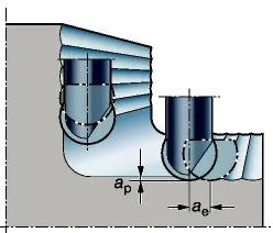
2.6.1 Indexing Mechanism of Indexing Head – Parts, Types and Working:
A system for separating the peripheral of a workpiece into any number of equal portions is known as an indexing mechanism. The indexing head is the machine that performs the indexing mechanism. A splitting head or spiral head is another name for an indexing head.
It's a specialist instrument that allows you to index a workpiece in a circular fashion.
The Indexing Mechanism is mostly used to precisely trim gear teeth. This device ensures that the gear's teeth are evenly spaced.
This device is also used to mill milling cutter flutes, mill curved slots, and drill a bolt hole circle around a part's circumference.
Milling machines are the most common machines that use this indexing technique. Grinders, drill presses, and boring machines all utilise this mechanism.
The indexing mechanism can also be used to make square or hexagonal bolts, splines on shafts, fluting drills, taps, and reamers, among other things.
A special attachment called as a division head or indexing head can be used to create this indexing technique.
2.6.2 Parts Used in Indexing Mechanism:
Indexing Plate – The indexing plate is a circular plate with holes that are evenly spaced. An indexing plate must have at least 6 holes. This indexing plate is attached to a crank, which in turn is attached to a handle. In the Simple Indexing Mechanism, this indexing plate is stationary, but it can move in the Differential Indexing Mechanism.
Crank – This crank has a handle that is manually rotated to give the worm shaft and worm the initial rotation, which is then transferred to the worm wheel.
Crank Pin – Crank Pins are used to keep the crank from rotating. The crank pin is put into the entire indexing plate, which is stationary and does not rotate, locking the crank's rotation.
Worm Shaft – The crank is connected to this shaft, which revolves with it. It is the link between the crank and the worm.
Worm – The worm shaft connects the worm to the crank. This worm has a threaded screw-like appearance. It's a worm with only one thread. When the crank is rotated using handle this worm also rotates due to rotation of worm shaft and a single tooth in worm wheel which is connected to the worm passes through the worm.
Worm Wheel (W.W) – The worm wheel has teeth that resemble gears. When the entire worm wheel's teeth have passed through the worm. One spin of the worm wheel is completed.
Spindle: The worm wheel is attached to the spindle, which revolves in tandem with it. When all the teeth of worm wheel pass through the worm, this worm wheel completes one rotation and the spindle connected to the worm wheel also completes one rotation. The face plate connects the spindle to the plate.
Face Plate – This face plate is attached to the spindle and revolves in tandem with the spindle. The workpiece is attached to this face plate, and the workpiece rotates with the face plate.
Change Gears – These gears are employed in differential indexing mechanisms to allow the indexing plate to rotate forward or backward as needed. These gears are attached to the worm wheels and take the rotation of the worm wheel as input and output to the indexing plate.
The indexing head is the mechanism that is made up of all of these pieces.
In this post, we'll look at two different sorts of indexing mechanisms:
1) Simple Indexing Mechanism
2) Differential Indexing Mechanism
1. Simple Indexing Mechanism:
The indexing plate's handle is manually rotated at first. The crank rotates as well as the handle. The worm shaft attached to the crank spins as the crank revolves, and the worm rotates as well.
When the worm rotates, the worm wheel's teeth pass through the worm, causing the worm wheel to rotate partially. One tooth of the worm wheel passes through the worm when it completes one complete rotation.
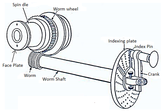
Simple Indexing Machine
The worm wheel revolves, and the spindle and face plate connected to it do as well. The worm wheel rotates the workpiece, which is attached to the face plate.
The indexing mechanism is mostly used to trim spur gear teeth. It's also used to mill grooves in reamers and taps, as well as spacing holes on a circle.
Case 1:
Let's imagine the worm wheel has 40 teeth and we need to machine 8 teeth in the workpiece. As a result, the number of crank handle rotations necessary to cut one tooth in the workpiece is = 1/8 x 40 = 5. To cut one tooth in the workpiece, 5 crank rotations are required.
The crank pin will be put in the indexing plate after every five rotations, locking the crank rotation as well as the workpiece rotation, allowing the workpiece to be machined at this time.
One tooth or worm wheel passes by the worm in one rotation of the crank, and five worm teeth pass by the worm in five rotations.
When five teeth of the worm wheel pass through the worm, one tooth is cut in the workpiece. For every fifth tooth of the worm wheel that crosses the worm, one tooth will be cut in the workpiece.
Hence When there are 40 teeth in the worm wheel and 8 teeth to be cut in the workpiece, it takes 5 rotations of the crank handle to cut one tooth in the workpiece.
Case 2:
We must mill 7 teeth in the workpiece in this scenario, which is not a factor of 40. To cut one tooth in a workpiece, the number of crank handle rotations necessary will be = 1/7 x 40 = 5 entire 5/7 rotations, i.e., 5 full rotations and 5/7 revolutions of the crank handle.
Because a fraction of a crank handle rotation is necessary. As a result, the indexing plate holes will be employed to obtain this fractional crank rotation.
15/21 is another way to write 5/7. To do this, a 21-hole indexing plate will be used. i.e., 5 full rotations of the crank handle, followed by another 5 full rotations of the crank handle until the 15th hole of the 21-hole indexing plate is reached.
This is the primary purpose of the indexing plate with holes; it is most commonly used when a mixed proportion of rotation of the crank handle is required.
2. Differential Indexing Mechanism:
When the percent of rotation of the crank handle cannot be reached using holes in the indexing plates, differential indexing is employed.
This situation occurs when the workpiece has to be divided into a number of divisions which is greater than the maximum number of holes an indexing plates can have.
The maximum number of holes in an indexing plate is 66. Differential Indexing Mechanism is utilised for more than 66 divisions.
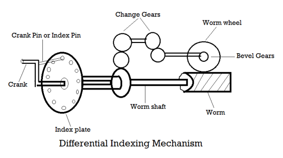
Some change gears are utilised in differential indexing mechanisms, as well as elements of simple indexing mechanisms. These change gears are utilised to shift the indexing plate forward or backward as needed in order to acquire the desired workpiece division.
Assume we need to drill 67 holes in the project or workpiece. After each cut, the task should rotate 1/67 of the overall rotation.
To cut one tooth in a workpiece, the number of rotations required is 1/67 x 40.
We can't perform this with a basic indexing mechanism because we don't have an indexing plate with 67 holes.
Now we'll look at how a differential indexing method can help us achieve this.
The change gears are coupled to the change gears through bevel gears and transfer rotation in a 90-degree angle in a differential indexing system.
These shift gears are connected to the indexing plate and rotate it to a degree so that we can cut a specific number of cuts in the work.
Using simple indexing, we can rotate the task to 1/66 of total rotation, but we need to rotate it to 1/67 of complete rotation.
If the work has two points A and B, each of which rotates 1/66 of the total rotation, then point C falls between these two points, and AC rotates 1/67 of the total rotation.
If we rotate the crank to get to AB or 1/66, we must either return a certain distance to get to 1/67 or reduce rotation by a certain amount to get to 1/67 instead of 1/66.
By turning the indexing plate in the opposite direction of the crank, we can reduce the amount of rotation by a certain amount.
The amount that the indexing plate must revolve in order to achieve 1/67 rotation instead of 1/66 = 1/66 - 1/67.
Index Plate Rotation = 1/66–1/67...... (i)
Now we must determine the change gear ratio required to rotate the index plate to 1/67 of total rotation.
We know that Gear Ratio (G) equals Output Rotation (No) divided by Input Rotation (Yes). (Ni)
We also know that the rotation of the worm wheel is the input rotation for the change gear.
Because the job must be divided into 67 pieces. Assume that the crank rotation is 1/67.
Now worm wheel rotation = 1/67 x 1/40 (worm wheel gear ratio is 1/40).
Now, input the change gear rotation (Ni) as 1/67 x 1/40.
The output rotation, i.e., the rotation of the index plate, is now G x Ni.
1/67 x 1/40 x G = (ii)
When we combine eqs I and (ii), we obtain
1/66 – 1/67 = G x 1/67x 1/40 = 1/66 – 1/67
G = 40/66 (67 – 66) = 40 / N (needed) (N (needed) – N (available)
In a differential indexing system, this is the generalised formula for computing the gear ratio of change gears.
If the gear ratio has a negative sign, the indexing plate should be rotated in the opposite direction of the crank handle, and if it has a positive sign, it should be rotated in the same direction as the crank handle, according to this formula.
Using the differential indexing mechanism, we can divide the job into more divisions than the maximum number of holes allowed on the indexing plate.
2.6.3 Tread cutting mechanism
Thread cutting on the lathe creates a helical ridge on the workpiece with a consistent section. This is accomplished by making many cuts with a threading tool bit of the same shape as the needed thread form.
Practice Exercise:
1. You'll need a piece of round material converted to an outer tread Diameter for this threading practise exercise.
2. Make an undercut for the tread equal to its single depth plus.005 inch using a parting tool or a specially ground tool.
3. Use the formula below to calculate the single depth for unified threads:
d = P x 0.750
Where d = Single Depth
P = Pitch
n = Number of threads per inch (TPI)
Infeed Depth = .75 / n
To cut a correct thread on the lathe, it is necessary first to make calculations so that the thread will have proper dimensions. The following diagrams and formulas will be helpful when calculating thread dimensions.
Example: Calculate the pitch, depth, minor diameter, and width of flat for a ¾-10 NC thread.
THREAD CALCULATIONS
1. For this threading practise activity, you'll need a piece of circular material that has been changed to an outer tread diameter.
2. Using a parting tool or a specially ground tool, make an undercut for the tread equal to its single depth plus.005 inch.
3. To compute the single depth for unified threads, use the formula below:
P = 1 / n = 1 / 10 = 0.100 in.
Depth = .7500 x Pitch = .7500 x .100 = .0750 in.
Minor Diameter = Major Diameter – (D + D) = .750 – (.075 + .075) = 0.600 in.
Width of Flat = P / 8 = (1 / 8) x (1/10) = .0125 in.
Procedure for threading:
1. Reduce the speed to about a quarter of the turning speed.
2. Adjust the quick-change gearbox to the desired thread pitch. TPI (threads per inch) is a unit of measurement for the number of threads
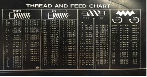
Figure: Chart of Thread and Feed
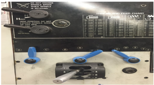
Figure: Gearbox Configuration
3. For right-hand threads, set the compound rest to 29 degrees to the right.
Figure: 29 Degrees
4. Attach a 60-degree threading tool bit to the lathe centre point and adjust the height.
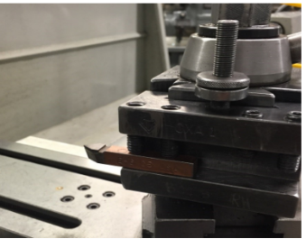
Figure: Threading Tool with a 60-Degree Angle
5. Using a thread gauge, align the tool bit and the job at right angles.
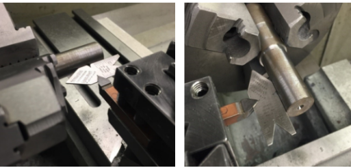
Figure: Positioning the tool for thread cutting with the Center gauge
6. Coat the threading area with a layout solution.
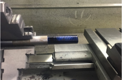
Figure: Shows the layout.
7. Using both the compound and cross feed, move the threading tool up to the component. Set both dials of the micrometre to zero.
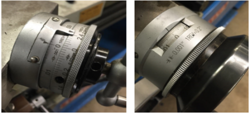
Compound Figure Cross Feeding (Figure)
8. Reset the cross feed to zero by moving the back tool off the work and moving the carriage to the end of the portion.
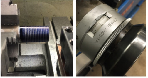
Figure: Cross feed to zero at the end of the part
9. Feed in.001 to.002 inch using only the compound micrometre.
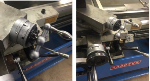
Figure: .002-inch compound feed
10. Engage the half nut and turn on the lathe.
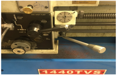
Figure: Half Nut and on/Off Lever
11. Using no cutting fluid, make a scratch cut on the part. At the conclusion of the cut, disengage the half nut, stop the lathe, and back out the tool using the cross feed. Reset the carriage to its original position.
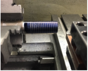
Figure: Starting Position
12. Using a screw pitch gage or a rule check the thread pitch. TPI (threads per inch) is a unit of measurement for the number of threads
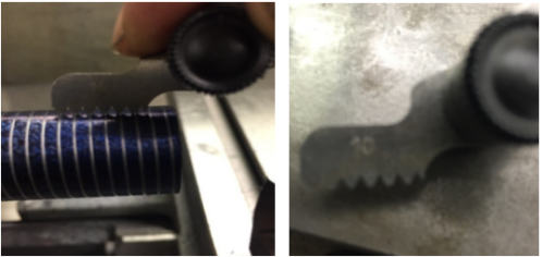
Figure: Gage for Screw Pitch Figure: Gage for Screw Pitch (10)
13. Using cutting oil, feed the compound in.005 to.020-inch increments for the first pass. Reduce the depth of cut to.001 to.002 inch as you come closer to the ultimate size.
14. Repeat steps 14 through 14 until the tool is within.010 inch of the finish depth.
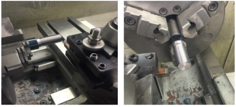
Figure: Threading procedure
15. Use a screw thread micrometre, thread gauge, or the three-wire technique to check the size.
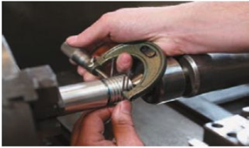
Figure: Measurement of three wires
16. To protect the thread from damage, chamfer the end.
2.7.1 Quick Return Mechanism: Definition, Types, Working Principle, Applications, Advantages, Disadvantages:
What is the Quick Return Mechanism?
A quick return motion mechanism is used in the shaper and slotter machine in which the circular motion is converted into reciprocating motion so that the slider moves forward and backwards. The cutting process occurs in the forward motion, but there is no corresponding cutting in the reverse direction.
Quick Return Mechanism Types:
Quick return mechanisms come in three varieties:
- Whitworth Quick Return mechanism
- Crank and Slotted Link Mechanism and
- Hydraulic Drive
- Whitworth Quick Return Mechanism:
The oscillatory motion is created by converting the rotating motion. The bull gear is utilised in this device, which features a crank pinion.
The connecting rod connects the pin at one end to the ram at the other end of the connecting rod, which slides over the crankpin and into the slot of a crank plate.
The pinion is driven by the electric motor shaft, which rotates the gear. The bull gear now rotates in tandem with the crankpin, and the sliding block moves into the crank plate's groove.
As a result of this operation, the connecting rod causes the ram to travel up and down.
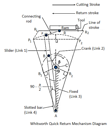
- Crank and Slotted Link Mechanism:
Whitworth devised this system in the 1800s. A slider, crank, fixed link, slotted lever, connecting rod, and ram make up the mechanism.
The slider and fixed link are connected to the crank. When the cranks begin to rotate, the connecting rod pushes the ram forward and backward.
From rotational motion, the motion is translated to linear motion here.
Please see the diagram for a better understanding.
Crank and slotted link mechanisms are commonly employed in shaping machines such as slotters and shapers to produce flat surfaces on workpieces.
In this mechanism, the return stroke is substantially faster than the forward stroke.
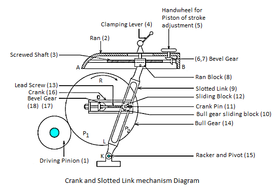
- Hydraulic Drive:
The hydraulic drive has a reciprocating piston inside the hydraulic cylinder. Between the ram and the piston lies the piston rod. As a result, the piston reciprocates with the ram.
There are two entries at the cylinder's end, as shown in the diagram. A control valve with four passages is installed below it.
The remaining two entries from the cylinder to the control valve are connected through a reservoir.
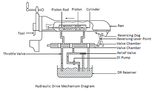
Quick Return Mechanism Working Principle:
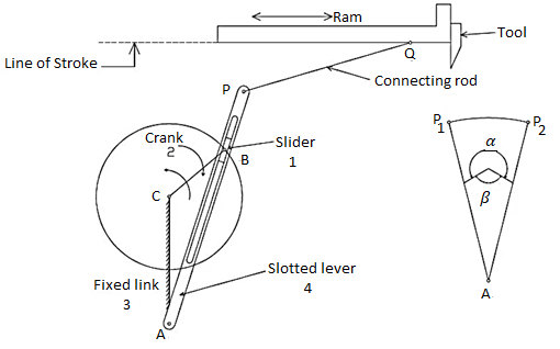
There are four links in the diagram, and they are Slider, Crank, Frame, and Slotted Lever. It is also linked by a pair, which are as follows:
- Frame and Slotted lever: Changing the Pair
Now Frame and Crank: Changing the Pair
Crank and Slider: Changing the Pair
Now Slider and Slotted lever: Sliding Couple
2. There are three turning Pairs and one sliding pair. It is also known as the Inversion of the Single slider crank chain mechanism. The connecting rod is fixed here.
1. The slider is free to slide in the slotted lever, and the slotted lever's upper end is linked to the shaper machine's ram by a linkage.
2. At points A and B, the crank and slotted lever are attached to the frame.
3. The crank and slotted lever are connected to each other via a slider.
When the power is turned on, the crank begins to rotate, and the motion is transferred to the slider, which is fitted inside the slotted lever and therefore begins to oscillate.
Now, when the ram moves ahead, it creates an angle of beta, which is registered, and it creates an angle of alpha, which is also documented.
The beta angle is greater than the alpha angle, as shown in the diagram. As a result, cutting strokes take longer than returning strokes.
Applications of Quick Return Mechanism:
These are the following applications of Quick return mechanism:
1. It is used to flatten the workpiece in the shaper machine.
2. The same machine is utilised in the Slotter and Planer.
3. It's also found in the Screw press, the Mechanical Actuator, and the Rotary Internal Combustion Engine.
Advantages of Quick Return Mechanism:
These are the advantages of Quick return mechanism:
1. The procedure is fully automated.
2. The mechanism's construction isn't overly sophisticated.
3. It can cut, flatten, and slot the workpiece, among other tasks.
4. Because of the quick return stroke, the idle time is reduced.
Disadvantages of Quick return mechanism are:
1. Because there is no contact with the work during the returning stroke, no cutting occurs, and the process takes a long time to complete.
2. In comparison to the return stroke, the forward stroke takes a long time.
3. Performing procedures requires more electricity.
4. Friction exists between the slider and the piston.
5. Continuous Because of the heat generated inside the piston, it will not work, and wear and tear may occur.
6. Linkage balancing is a serious issue because this device is also related to links.
Key takeaways:
A quick return mechanism is a device that generates a reciprocating motion in which the return stroke takes less time than the forward stroke. It uses a system of links with three turning pairs and a sliding pair to be driven by a circular motion source (usually a motor of some sort). It can cut, flatten, and slot the workpiece, among other tasks. Because of the quick return stroke, the idle time is reduced. The Quick Return Ratio is the ratio of time taken for forward stroke to time taken for return stroke. This is also the same as the angle swept by the crank in the respective strokes.
2.8.1 Capstan and Turret Lathe:
A capstan and turret lathe are used to manufacture any number of identical workpieces in less time. These lathes are the next step in the evolution of engine lathes. Pratt and Whitney invented the capstan lathe for the first time in 1860.
The capstan and turret lathe consists of:
1. Bed
2. Headstock with all gears
3. A saddle with a four-station tool post that can hold four different tools.
4. A tool-post attached to the carriage's back. It inverts the position of a parting tool. The tool post on the cross slide is manually indexed.
5. Instead of a tailstock, this machine has a hexagonal turret positioned on a slide that rests on the bed.
2.8.2 Working of Capstan and Turret Lathe
The turret's six faces can each contain six or more different tools. Each tool can be brought in line with the lathe axis in a regular succession by automatically indexing the turret. Collets or chucks are used to hold the workpieces.
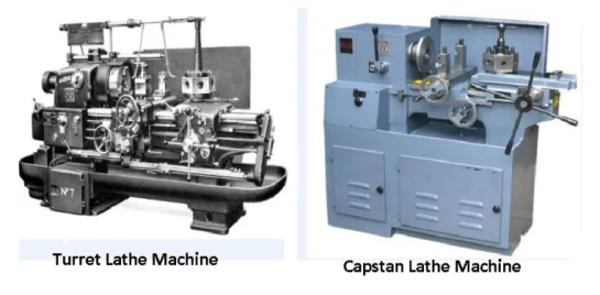
Adjustable stops govern the longitudinal and cross feed movement of the turret saddle and cross slide.
Different tools set at different stations are enabled by these stops. To move by a pre-set amount in order to perform different operations on repeating workpieces without having to measure the length or diameter of the machined surface in each case.
A capstan and turret lathe's unique properties allow it to execute a variety of tasks, including:
1. Turning.
2. Drilling.
3. Boring.
4. Cutting the thread
5. Reaming.
6. Necking.
7. Chamfering.
8. Cutting-off.
9. And a slew of other procedures performed in a predictable order to generate a huge number of similar components in a short period of time.
2.8.3 The Capstan or Ram Type Lathe
The figure depicts a capstan or ram type lathe. The hexagonal turret is carried on ram or a short slide by this mechanism.
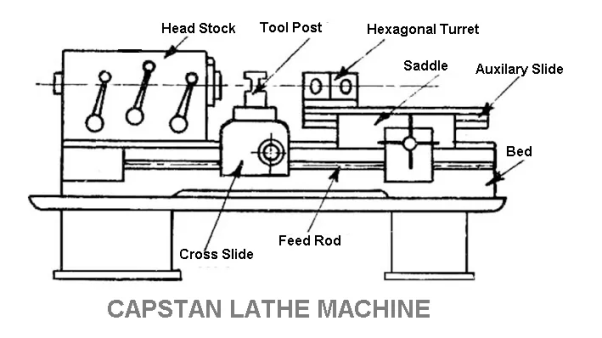
The ram is mounted longitudinally on a saddle that is attached to the lathe bed ways. This machine is made of lightweight materials and is ideal for processing smaller diameter bars.
The tools are installed on the hexagonal turret's six faces and the square turret's six faces.
When the ram moves from left to right, the feeding movement is obtained. The turret indexes automatically when the ram is shifted backwards. The tool mounted on the next face then goes to work.
2.8.4 The Turret or Saddle Type Lathe
Another sort of lathe machine is the turret lathe. It is used for repetitive production of same duplicate parts, which by the nature of their cutting process are usually replaceable. The hexagonal turret as depicted in the illustration.
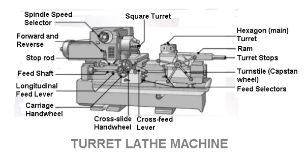
It is directly installed on a saddle, and the entire unit slides back and forth on the bed ways to apply feed.
The construction of this sort of turret lathe machine is more substantial. It's especially well-suited to chucking and larger-diameter bar work. Longer workpieces can be fed into the machine than a capstan lathe can.
2.8.5 Principle Parts of Capstan and Turret Lathes
Except for the turret, the turret lathe has essentially the same components as the engine lathe. It also has a complicated mechanism that makes it appropriate for large production tasks.
Following are the main parts of a capstan and turret lathe:
- Bed.
- Headstock.
- Cross slide and saddle.
- The turret saddle and auxiliary slide.
1. Bed
The carriage and turret saddle are installed on the bed, which is a large box-like casting with precise guideways. Under heavy-duty conditions, the bed is designed to ensure strength, rigidity, and alignment stability.
2. Headstock
The headstock is constructed from massive castings. It's at the far end of the bed, on the left. The following are the various types of headstocks used in capstan and turret lathes:
- Step cone pulley driven headstock.
- Direct electric motor driven headstock.
- All geared headstock.
- Preoptive or preselective headstock.
1. Step Cone Pulley Driven Headstock
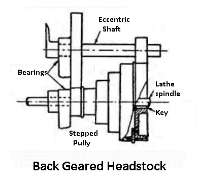
Small capstan lathes are fitted to this style of headstock, which is the most basic. When the lathe is used to process workpieces with a tiny and nearly constant diameter. Only three or four steps of the pulley can meet the machine's requirements.
Unlike an engine lathe, where the machine spindle may be started, stopped, and reversed by pushing a foot pedal, the machine requires a unique countershaft.
2. Electric Motor Driven Headstock
Both the machine's spindles and the motor's armature shaft are one and the same in an electric motor-driven headstock.
Direct control of the motor allows for any speed differential or reversal. Three or four are available, and the machine is designed for workpieces with smaller diameters that revolve at high speeds.
3. All Geared Headstock
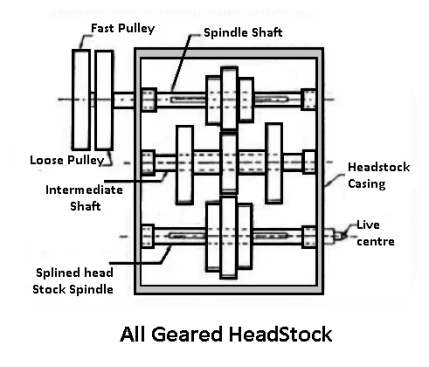
The headstocks on larger lathes are geared, and a separate mechanism is used to change the speed by actuating levers. The machine was not stopped while the speed was changed.
4. Preoptive or Preselective Headstock
It's an all-geared headstock with features like speedy stopping, starting, and speed charging for various tasks, as well as the ability to push a button or pull a lever.
The spindle speed must alter for different activities and for turning different diameters. The next operation's needed speed is chosen ahead of time. And the speed-changing lever has been set to the desired setting.
A button or a lever is simply actuated when the initial operation is completed. And, without stopping the machine, the spindle begins rotating at the set speed for the second operation. Friction clutches have an impact on this innovative mechanism.
5. Cross-Slide and Saddle
Hand-operated cross slides are secured on the lathe bed at the desired position in small capstan lathes. Larger lathes and heavy-duty turret lathes are frequently supplied with two carriage configurations.
- Conventional type carriage
- Side hung type carriage
1. The Conventional Type Carriage
The traditional carriage spans the distance between the front and back bed-ways. It also has four station tool posts in the front and one rear tool post at the back of the cross slide.
2. The Side-hung Type Carriage
The saddle rides on the top and bottom guideways on the front of the lathe bed on the side-hung type carriage, which is usually equipped with heavy-duty turret lathes. The design allows for the swinging of a bigger diameter workpiece without the cross-slide interfering. Hand or power feeding can be used to feed the saddle and cross slide longitudinally or across.
Stop-bars or shafts can be used to control the longitudinal movement of each tool. It's positioned against the bed's and carriage's halt. These stops are placed such that each tool feeds into the work to the desired length, allowing the job to be duplicated without having to check the machining length for each operation.
These act as a dead-stop for small head-operated tool movement to complete the cut after stopping the first trip out the feed. To synchronise with the tool's indexing, the stop bars are indexed by hand.
The tools are fixed on the tool post, and the correct heights are achieved with the help of a rocking or parking piece.
The Turret Saddle and Auxiliary Slide
The turret saddle spans the gap between two bed-ways in a capstan lathe. Furthermore, the top face is precisely cut to serve as a bearing surface for the auxiliary slide. On the lathe bed-ways, the saddle is adjusted and clamped in the desired position. The auxiliary slide holds the hexagonal turret.
In a turret, the top of the saddle is directly attached on the turret, and any movement of the saddle affects the turret. The turret's mobility can be controlled by hand or by power. The turret is a tool storage with a hexagonal design that can accommodate six or more tools.
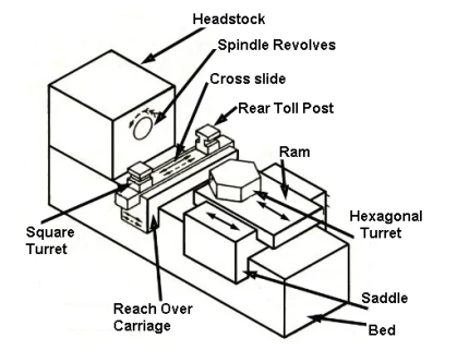
Each turret face is meticulously machined. Each face has precisely bored holes through the centre od to accommodate shanks of various tool holders.
When aligned with the headstock spindle, the centre line of each hole aligns with the lathe's axis. In addition to these holes, each face of the turret has four tapped holes for fastening various tool holding attachments. There is a clamping mechanism in the centre of the turret on the top of it that locks the turret to the saddle.
The saddle is equipped with six stop bars. For duplicating workpieces, this restricts the movement of each tool installed on each face of the turret to a set amount.
The turret is moved away from the spindle nose when one operation is accomplished. A device on the bed and in the turret saddle automatically indexes the turret. So that the tool on the following face is parallel to the work.
2.8.6 Difference Between Capstan and Turret Lathe Machine:
The following 17 Point is the Difference Between Capstan and Turret Lathe Machine:
Sr. No. | Capstan Lathe Machine | Turret Lathe Machine |
1. | The capstan lathe is a light-duty equipment that can be used for a variety of tasks. | This is a powerful machine. |
2. | In The tool head is mounted in the ram, and the ram is positioned on the saddle of the capstan lathe. | The saddle is where the tool head is affixed. |
3. | To This ram movement necessitates the provision of nourishment. | It is necessary to supply feed saddle movement here. |
4. | Because ram movement is limited for small type workpieces, this is employed. | And because the ram movement is not limited or set, this one is employed for larger workpieces. |
5. | Because of the light construction, this is a quick form of work. | This is a machine that works slowly. |
6. | A Because of the non-rigid design, a hefty cut is not possible. | In Turret lathe, turret lathe, turret lathe Because to the robust design, heavy cutting is not possible. |
7. | It is a horizontal lathe of some sort. | However, this one can be used for both horizontal and vertical tasks. |
8. | Crosswise movement of the turret head is not possible. | The turret head can be moved crosswise here. |
9. | In The turret head on the capstan lathe is easy to move because it glides over the ram. | It It's tough to move the turret head and saddle at the same time. |
10. | To The collect is used to retain the workpiece. | A jaw chuck is utilised to hold the workpiece here. |
11. | This machine can only machine workpieces up to 60mm in diameter. | This machine can only machine workpieces with a diameter of 60mm. |
12. | This lathe machine has a smaller lengthwise movement. | There's more. |
13. | The head of the turret can be moved manually. | The head of the turret cannot be moved manually. |
14. | Because there is a certain amount of feed and cut depth, machining is constrained compared to a turret lathe. | Machining can be improved by increasing the feed rate and cutting depth. |
15. | Construction is lighter. | The construction is substantial. |
16. | There is no such facility as a turret lathe here. | In The ability to move the turret at a right angle to the lathe axis is provided by a turret lathe. |
17. | Both can be mass-produced in large quantities. | Both can be mass-produced in large quantities. |
2.9.1 Single spindle automatic lathe:
Single spindle automatic lathes are commonly used for quantity or mass production (by machining) of high-quality fasteners, such as bolts, screws, studs, bushings, pins, shafts, rollers, handles, and other small metallic parts, from long bars or tubes of regular section, as well as from separate small blanks. A typical single spindle automatic lathe is shown in the diagram. Single spindle automats, unlike semiautomatic lathes, are:
• Preferably and basically utilised for large-scale production, such as huge lots and mass production.
• Always used to produce jobs that are rod, tube, or ring in nature and are of a smaller size.
• Run fully automatically, including bar feeding and tool indexing, over a lengthy period of time, repeating the same machining cycle for each product.
• Up to five radial tool slides are provided, which are moved by cams mounted on a cam shaft.
• Smaller in size and power, yet with faster spindle speeds
2.9.2 Kinematic system and working principle of automatic lathes of common use.
- Single spindle automatic lathe
This general purpose and widely used automatic lathe is also known as single spindle automatic screw cutting lathe (SSASCL) because such lathes were introduced aiming mainly mass production of fasteners having screw threads. The usual kinematic system of a single spindle automat is shown schematically in Fig. In such lathes, the following major functions are automatically performed in sequence with appropriate synchrony:
Spindle speed change – magnitude and direction of rotation
Bar feeding transverse tools – feeding turret indexing and travelling
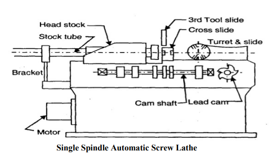
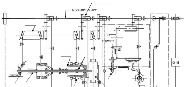
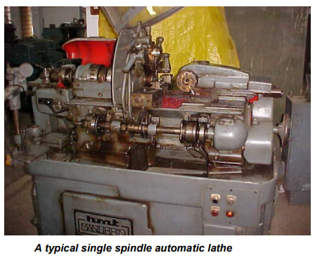
2.9.3 Swiss Type Automatic Lathe
These single spindle automatic lathes have the following features and applications:
- In respect of application:
Precision machining is used for lot or mass manufacturing of thin slender rod or tubular work, such as components of miniature clocks and wrist watches;
- Job size (approximately)
Diameter range – 2 to 12 mm
Length range – 3 to 30 mm
Dimensional accuracy and surface finish – almost as good as provided by grinding
- In respect of configuration and operation
As shown in Fig, the headstock travels, allowing axial feed of the bar stock against the cutting tools.
1. There is no turret or tailstock.
2. For small work diameters, a high spindle speed (2000–10,000 rpm) is required.
3. The cutting tools are fed radially (up to five total, including two on the rocker arm).
4. Drilling and threading tools, if required, are moved axially using swivelling device(s)
5. Grinding is used to prefinish the cylindrical blanks, which are then passed via a carbide guide bush as indicated.
These lathes are extremely small, possibly as small as 6 inches by 2 feet, but they are totally automatic, extremely precise, and fairly expensive. Now the characteristics of the products are that they are extremely little. It's a mass-production machine, but the products are very small, slender rod-like products like the ones you see here, with diameters ranging from 2 millimetres to 10 millimetres at most. The length might range from 3 millimetres to 15 or 20 millimetres. Precision, certainly, the dimensions accuracy and finish will be in the micron range, and speed, because the diameter is so small. The speed should be very high in this setup, which is highly unusual. The headstock can be seen moving. Now, if you want to machine turn a long rod like this, you usually start from this side. Now, if we take a long, thin rod that is projected thus far, there will be a great deal of bending force. There is a tool guide job guide via which the job is passed to avoid this. This is referred to as a job guide, and the bush and cutting tools are mounted along it as the task progresses. As a result, the projection length or bending moment will be modest at all times. As a result, the headstock will progressively shift, mimicking the feed motion. As a result, this is one of its distinguishing features. So, the tool will be nearly stationary, moving radially just after this tool work guide, and the job will move through that, so no matter how long the job is, the over or bending movement will be little, and there will be 5 radial cutting tools indicated over here. One is a front slide, which is a real vertical slide, and the other is an inclined slide. These two slides will be mounted on a rocker arm, which will oscillate when the cutting tool is engaged, and when the rocker arm rotates in this direction, the tool will be engaged into work. As a result, this is the fundamental Swiss type automatic configuration. These 11 are primarily used for very small mechanical components, such as little pins found in wrist watches and other related items.
This is a Swiss style automatic where the bar is held in place by a collet, which is called a stationary collet and is actuated by a push tube. The power is now transferred from the motor to the spindle via the shaft. So, the spindle turns in this direction, together with the collet and the work, and then the power is transferred to the cam shaft, which rotates slowly. Now, when the cam shaft rotates, this cylindrical cam pulls the entire headstock forward through the tool job, guiding the bush against the cutting tools. All five cutting tools are actuated by five or four cams and are installed on the cam shaft. When the task is finished, the collet opens, the rod is pushed by gravity, it is arrested by a tool, and the process is repeated.
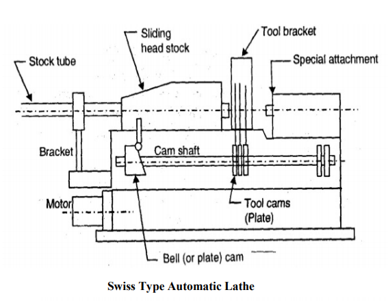
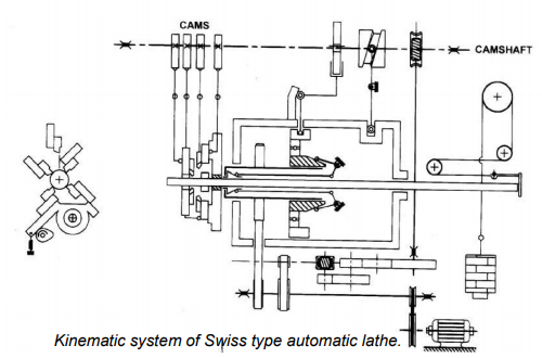
2.9.4 Multi spindle automatic lathes:
For a higher rate of production of jobs that are often smaller in size and have simpler geometry. It is preferable to use multi spindle automated lathes with four to eight parallel spindles. Multi spindle automated lathes, unlike multi spindle turret lathes;
• have a horizontal orientation (for working on long bar stocks)
• mostly work with long bar or tubular blanks
Parallel action or progressively working multiple spindle automats are other options. Machining of the inner and outer races in mass production of ball bearings are, for instance, machined in multi spindle automatic lathes.
Key takeaways:
• A single-spindle lathe is a numerically controlled lathe with a single main spindle. A multi-spindle lathe, on the other hand, has six to eight primary spindles that all work at the same time.
• The production rate is increased. Speeds are obtained in a variety of ranges. It is possible to accommodate a variety of tools. It is possible to chuck larger workpieces.
• A Multi Spindle Automatic Lathe can perform a variety of operations, such as boring holes, turning, chamfering, threading, grooving, and drilling, by moving the workpiece between six and eight places in the machine.
2.10.1 Gear Shaping – Types, Working, Diagram, Advantages:
Types Of Gear Shaping:
One of the processes for creating gears is gear shaping. In this process gear tooth are accurately sized and shaped by cutting them by a multipoint cutting tool.
The following is a list of various gear shaping procedures, followed by descriptions:
(a) Gear cutting by gear shaper.
(b) Rack planning process.
(c) Hobbing process.
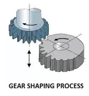
The geometrical accuracy of the circular component depends on:
(a) The rotational accuracy of the workpiece.
(b) Tool movement that is parallel to the work-spindle axis.
(c) The impact of tool abrasion.
It is independent of the tool profile's shape. Furthermore, the procedure is ongoing.
Gear Shaper machine
The forementioned generating principle is used in gear shapers in the following way:
The cutter is hardened disc-shaped and slightly dished at the bottom (ground with top rake and clearance) to facilitate cutting. The teeth have the tooth profile and pressure angle that you choose.
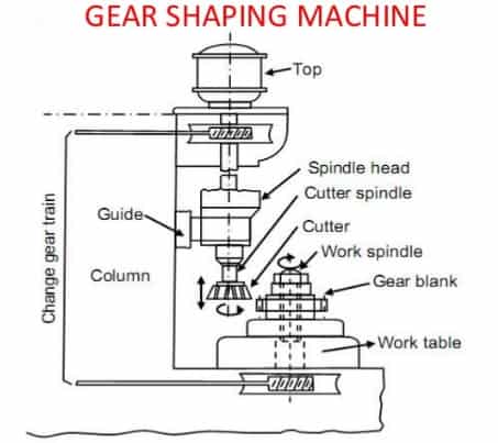
Gear shaping machine
The cutter is reciprocated at the desired cutting speed to remove stock from the workpiece's face, and then gradually fed radially to plunge it for the right teeth depth using a cam. On non-cutting or return strokes, a relieving mechanism allows the cutter to clear the job.
The continuous generation motion is achieved by feeding the cutter to full depth and gently rotating the cutter and workpiece in the correct ratio of their respective number of teeth using a chain of gears, which includes change gears. The cutter is regarded as the driving gear, and the workpiece as the driven member, with an external link of the gear train influencing the precise transmission of motion.
When the cutter has plunged to the exact tooth depth (specified beforehand) into the workpiece and the teeth have been cut fully and uniformly across the entire periphery of the workpiece gear, the workpiece gear is fully created. After the workpiece gear is totally cut, the machine automatically comes to a stop.
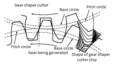
Gear shaper principle
Figure depicts the cutting motion of a pinion type cutter to generate a gear. The generating method of cutting gears has the advantage of being able to cut properly gears with identical modules or DP but variable numbers of teeth using a single DP cutter module. As a result, the producing procedure is both functionally superior and cost-effective for gear manufacturing.
In conclusion, an involute gear will roll with any other involute gear of the same normal base pitch, and therefore this principle has been applied to the gear shaper (a method of gear manufacture). This cutter is made up of a pinion with relieved cutting edges, and both the cutter and the work are rotated around their respective axes to imitate the conditions that would exist if both components were complete gears rolling together at the correct centre distance.
This is accomplished by gearing the cutter to the job in the same ratio as the cutter's and final work's teeth. Cutting is accomplished by giving the cutter axial reciprocating motion in tandem with its rolling action, with the ram's stroke length being somewhat longer than the width of the blank.
- Pinion cutter gear shaping process
In this method instead of rack cutter, a pinion cutter having formed similar to gear to be produced is used
Gear shaping is used to trim spur and herringbone gears, among other things.
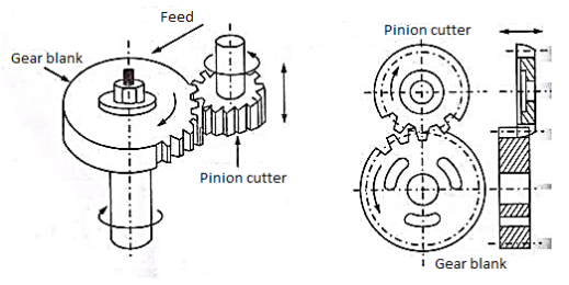
Pinion cutter gear shaping process
Principle: Teeth are created using a reciprocating and rotating cutter in conjunction with the rotating action of the workpiece.
Setup:
The reciprocating action, which is the main movement, is received by the gear shaping cutter. It reciprocates between 50 and 450 times each minute. Both the cutter and the workpiece spin at the same rate. When the cutter is to be fed into the depth of cut, it is given radial movement.
Working:
1) With the cutter reciprocating and blank stationery, the cutter is fed into full depth.
2) Both the cutter and the blank rotate at a high rate around their axes.
3) The cutter is fed to the workpiece at the same time.
Gear Shaping by Rack Shaped Cutter
A rack-shaped cutter called a rack type cutter is used to cut gear in this way. Figure depicts the principle in action. The working process is identical to that of a gear type cutter.
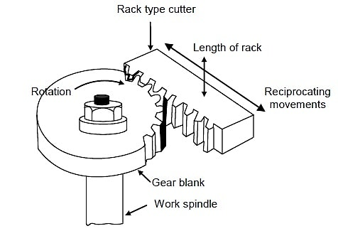
Gear Shaping by Rack Shaped Cutter
The gear blank is rotated (low rpm) as the rack type cutter reciprocates along a vertical line in this procedure. Only the downward stroke is used for cutting; the upward stroke is only a return action. The key difference between this procedure and the previous one is that once the entire length of the rack has been used, the gear cutting operation is halted in order to return the gear blank to its starting position, allowing another pass of gear cutting to begin. As a result, this technique is only used on occasion to cut bigger gears with a significant number of teeth around their edge.
Advantages Of Gear Shaping:
The following are the main benefits of the gear shaping process:
(a) Shorter product cycle time and suitability for mass manufacture of medium and large-sized gears.
(b) Other than worm and worm wheels, several sorts of gears can be manufactured.
(c) Gear cutting tolerances can be kept to a minimum.
(d) The gear tooth profile's accuracy and repeatability may be easily maintained.
(e) Regardless of the number of teeth in the gear, a single type of cutter can be employed for the same value of gear tooth module.
Disadvantages of gear shaping:
• Internal gears are not recommended.
• The gear shaper does not cut on the return stroke due to the reciprocating movement of the cutter.
Worms and worm wheels aren't possible to make with gear shapers.
• Due to periodic indexing, the rate of production is lower than the gear hobbing method.
• More machining time is required.
Applications of gear shaping:
1) Cutting spur gears.
2) Cutting herringbone gears.
3) Rachets gears.
4) Splines.
2.10.2 Gear Hobbing
The quality, performance, service life, safety, and dependability of high-end power transmissions are all determined by high precision gears. While there are a variety of ways for making these gears, such as milling or grinding, hobbing is the most common. When compared to grinding, the hobbing technique has the benefit of being more precise and efficient at a cheaper cost. (1) Though part geometry limits the application of this method, hobbing is still the most productive technique of gear teeth generation for external spur and helical gears. (2)
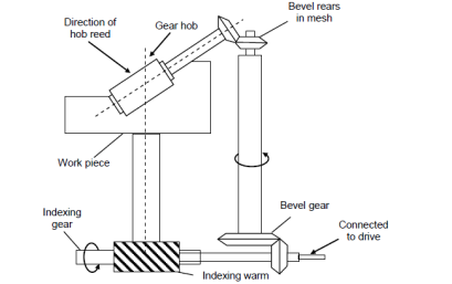
In the process of gear hobbing indexing movement, three critical parameters must be controlled: feed rate, angle between the axis of the gear blank, and the angle between the axis of the gear hobbing tool (gear hob). The image shows a schematic diagram of how a gear hobbing machine is set up. The hob's objectives are placed at an angle equal to the helix angle of the hob with the blank's vertical axis. If a helical gear is to be cut, the hob axis must be adjusted at an angle equal to the sum of the hob's helix angle and the helical gear's helix angle. Feeding the revolving hob till it reaches the desired depth of the gear tooth is how gear hobbing is done. The method of gear hobbing is classified based on the directions in which the hob is fed for gear cutting, but this should not be confused with the two different techniques for gear cutting that will be explained in the next paragraph. Hobbing with axial feed, radial feed, or tangential feed are the three different forms of gear hobbing. When the hob is fed parallel to the axis and along the face of the blank, it is referred to as axial feed. This process is used to make spur and helical gears. The hob is fed against the gear blank in a radial direction when the gear blank and hob axes are placed normal to each other. In the production of worm wheels, this type of feed is used. Tangential feed, which is employed for worms, occurs when the hob is held horizontally with its axis at a right angle to the blank's axis. The hob is set to the tooth's full depth before being fed forward axially. The hob is fed perpendicular to the gear blank's face. Worms are also produced using this procedure. (11) When it comes to gear hobbing, there are two basic cutting strategies: climb cutting and conventional cutting. The terms "climb" and "conventional" relate to the direction in which the hob feeds into the workpiece in relation to the table or spindle nose. When possible, it is advised that conventional cutting be employed for optimal stability during cutting. In traditional hobbing, the hob is fed into the piece, moving parallel to the blank axis toward the table or spindle nose. The hob is fed away from the table or spindle nose, parallel to the blank axis, in climb hobbing. (1) The three unique motions of the gear hob: tool rotation about its axis, tool axial displacement, and workpiece revolution around its axis must be determined by the direction and axial feed to establish which hobbing strategy should be utilised in a given application. (5) As a general rule, climb hobbing results in longer tool life and greater precision, but conventional hobbing results in a better finish.
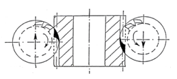
When hobbing, the tool's teeth, or hob's teeth, make simultaneous contact with the workpiece. These teeth generate involute tooth gaps in a generating method, thanks to the constant interaction of the tool and the workpiece rotating motion. (9) One of the complexities in hobbing is arranging the cutting configuration in a way that will produce the desired tooth profile, whether standard or modified in some way, as long as the cutting configuration corresponds to the selected design structure specifying the geometric and kinematic parameters of the tool's tooth profile such that the tooth trough in the gear is produced in an orderly manner and the cutting configuration corresponds to the selected design structure specifying the geometric and kinematic parameters of the tool's tooth profile such that Due to the synchronisation required to manufacture gear teeth, the kinematics of this complex operation is dependent on three relative motions between the gear and the work gear. The hob tool and the work gear move in a connected revolution ratio when gear hobbing. These revolutions are coordinated with hob axial-feed and are determined by the cutter's number of starts and the workpiece's number of teeth.
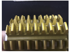
One of the most essential principles in gear hobbing is the generating process. The cutting tool geometry, among other things, can influence cycle times and tool wear in the gear production process. The hob is essentially a worm with cutting edges created by gashes sliced across it. A hob can alternatively be thought of as a collection of racks arranged around the circle of a cylindrical instrument. Each subsequent rack is axially adjusted to generate a worm, which is usually a single thread. To create changed tooth shapes, you can customise the shape of a cutting tool. Table shows the benefits of the various modifications:
Modification | Advantages |
Topping Hob |
|
Semi-Topping |
|
Protuberance |
|
Tool wear is also concept of gear manufacturing that is highly researched as it is very difficult to model and predict due to the generating-rolling principle that governs the hobbing kinematics. There are crucial gearing characteristics that might influence the tool life time in a very favourable or negative way when it comes to the wear effects of the tool geometry. Modifications to the hob's tooth profile can be made to enhance the manufacturing of a specific workpiece. These unique characteristics are frequently employed in industrial applications, but only internal business knowledge is currently available. During hobbing, the distinct chip generation on each cutting tooth causes various wear laws, which usually results in unequal wear distribution on the hob teeth. Certain faults in the hob will lead to tool wear, such as the simultaneous and intermittent participation of two or more cutting edges of the tool teeth in hobbing. As a result, substantial local wear at the tooth tip can occur, resulting in tool life loss. On specific jobs when a custom hob must be manufactured with longer runs, these flaws must be taken into account.
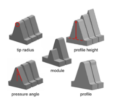
There are numerous elements to consider while optimising the gear hobbing process; one of the most essential elements is the cutting forces involved in this process, as the cutting forces will contribute to chip formation and tool wear throughout the hobbing process. As a result of the tool and machine wear induced by the forces, the pricing of the part in production may be affected. There are several models in which authors have built models to anticipate cutting forces, however due to the complicated nature of the kinematics of gear hobbing, there is currently no means to precisely evaluate cutting forces, tool wear, or the chip generation process. As indicated in Figure, cutting forces are often split into small cutting-edge parts.
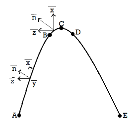
Material qualities, in addition to the geometries of the gear workpiece and the hobbing tool, have an impact on the gear hobbing process. High-speed steel and carbide are common materials for hob tools. The material for the hob is determined by the material of the gear blank and the speeds at which the hobbing procedure will be performed. Hobbing tools composed of solid tooling material, such as tungsten carbide, are commonly used to manufacture steel gear workpieces. Studies have also demonstrated that matching the substrate with a suitable coating can result in a significant increase in the applied cutting speed. Researchers have proposed new proposals and ways to improve the precision and efficiency of hobbing, such as simulating the kinematics of the hob. Machine control and tool development are inextricably linked, ensuring that gear manufacture improves with time.
2.10.3 Comparison of gear hobbing technology and gear shaping technology:
Machining accuracy
Gear hobbing has a high level of movement precision, yet gear shaping has an excellent profile and surface quality. Because of the following reasons:
1) The mechanical gear shaper's transmission chain is more complicated. The most notable difference is that the tool worm gear pair has one more pair than the gear hobber, implying that there is greater transmission error. The tool spindle's reciprocating motion and the table's moving portion are both easy to wear. The accumulated error of the pitch of the gear shaper must also be reflected on the gear because the tooth profile of the gear to be machined is obtained when meshing with the gear shaper without clearance, so the kinematic accuracy of the gear shaper is generally lower than that of the gear hobbing. It is important to utilise a gear shaper and a precision gear shaper in order to process gear with high precision. However, with the widespread usage of gear shapers, this problem has been effectively handled, as the CNC gear shaper's axes are independently controlled, the transmission chain is substantially shorter, and the transmission error is substantially decreased.
2) The circumferential feed, which can be selected, determines the number of tangents to form the profile envelope during gear shaping, whereas the number of tangents to form the involute envelope during gear hobbing is only related to the number of grooves and heads of the helix, and the number of tangents of the envelope cannot be increased or decreased by changing the number of grooves and heads of the helix. As a result, gear shaping has a far higher surface polish than gear hobbing, and the tooth profile error is also lower.
3) A gear shaper cutter installation fault has little impact on tooth profile error, however a hob installation fault will result in a considerable workpiece tooth profile error.
The gear shaper cutter is shaped like a spur gear or a rack. In comparison to hob, the manufacturing method is simple, making it easier to manufacture more precisely, resulting in improved gear machining precision. As a result, gears with low kinematic precision can be handled directly by gear shaping, rather than shaving or grinding, from the standpoint of machining accuracy. Gear and pre-shaving gear, on the other hand, have higher kinematic accuracy requirements (shaving does not improve kinematic accuracy), hence gear hobbing is preferable.
Productivity
In general, gear hobbing has a better productivity than gear shaping. Gear shaping can only compete with gear hobbing when the gear has a compact module, a large number of teeth, and a tiny tooth width. This is because:
1) The hob cuts while rotating, resulting in a faster cutting speed and reduced empty stroke loss. The gear shaper cutter is reciprocating, which restricts the rise in cutting speed, and the actual cutting stroke length accounts for just approximately a quarter of the overall stroke length, resulting in a substantial empty stroke loss.
2) Multiple hobs can be employed to increase rough hobbing efficiency.
3) Gear hobbing moving time is proportional to the number of teeth on the workpiece, but gear shaping moving time is solely dependent on the diameter of the workpiece. Gears having a big diameter and a tiny module, in other words, are suited for gear shaping.
Gear shaping productivity is generally lower than gear hobbing productivity when processing gears with more than 5 modules, due to the necessity to remove a large number of redundant metals. Due to the minimal number of metals removed, gear shaping is more efficient and accurate than gear hobbing when processing tiny module gears with a module of less than 2.5. Gear shaping has the same productivity as gear hobbing when processing gears with a medium module (2.5mm-5mm). In this scenario, gear hobbing is recommended. Gear shaping is not less productive than gear hobbing for some specific gears with big modules (such as sector gears, herringbone gears, racks, and so on).
As previously said, the technological scope of gear shapers is broader than that of gear hobbers due to the structure and tooth movement characteristics of gear shapers. All gears that can be processed by a gear hobbing machine (excluding worm gears) may be processed by a gear shaper. To put it another way, a gear shaper can work with internal gears or unusually shaped workpieces. They might not be able to be processed by a gear hobbing machine. Gear shapers, for example, utilise specialised tools and clamps to handle rack, involute spline, shorter spline shafts, and pieces with a unique circumferential profile. Because of various unique needs (such as a short empty cutter slot) and unique forms (such as multiple gears and internal gears), the hobbing machine can only finish the spiral gear processing on the gear shaper. Of course, gear hobbing has many advantages, such as the ability to machine left and right spiral gears with different helix angles, and the fact that gear hobbing only requires swinging the hob, whereas gear shaping necessitates the design and manufacture of a special spiral guide rail and corresponding gear shaper. Gear shaping's omnipotence isn't quite as good as gear hobbing's in this regard.
2.11.1 Lathe machine introduction
The Lathe was invented by Jacques de Vaucanson around 1751.
The lathe machine is a centuries-old machine. This machine was built at a very early stage, circa 1300 BC, when there were not many pieces constructed except for the headstock and tailstock. Metalworking lathes, on the other hand, evolved into heavier machines with thicker, more solid elements during the industrial revolution.
Electric motors supplanted line shafting as a power source in the 19th and 20th centuries.
The servomechanism was then used to drive lathes and other machine tools using a numeric, direct numerical control machine in 1950.
The lathe is the most adaptable machine tool of all the conventional machine tools.
Nowadays, manually operated machines exist in the same way that CNC machines do, and the lathe machine can even run manually with the help of a feed mechanism.
2.11.2 Lathe Machine Definition:
A lathe machine is a machine tool that removes metal from a workpiece to give it the shape and size that you want.
Metalworking, woodturning, metal spinning, thermal spraying, glass working, and parts reclamation all employ lathe machines.
Sanding, cutting, knurling, drilling, and deformation of tools used in making symmetrical objects along the axis of rotation are some of the other activities that you may conduct with the help of a Lathe Machine.
A lathe is made up of various parts. It's also referred to as the "Father of All Standard Machine Tools."
The purpose of a lathe is to remove metal in the form of chips from a piece of work by rigidly mounting it on a machine spindle and rotating at the needed speed, while a cutting tool is fed against the work longitudinally or transverse to shape and size it to the appropriate shape and size.
2.11.3 Parts of the Lathe Machine and their functions:
A lathe machine tool consists of several parts like:
- Headstock
- Bed
- Tailstock
- Carriage
- Saddle
- Cross-slide
- Compound rest
- Tool post
- Apron
- Lead Screw
- Feed rod
- Chuck
- Main spindle
- Leg
Head Stock:
The drive mechanism and electrical mechanism of a Lathe machine tool are housed in the Head Stock, which is located on the left side of the lathe bed. The work is held in place by the spindle nose, which has external screw threads and an internal Morse taper for retaining the lathe centre. It rotates at a varied speed thanks to a cone pulley or an all-geared drive. • Head Stock transmits power from the spindle to the feed rod, lead screw, and thread cutting mechanism through a hole running the length of the spindle.
Accessories mounted on headstock spindle:
- Three jaw chuck
- Four jaw chuck
- Lathe center and lathe dog
- Collect chuck
- Faceplate
- Magnetic chuck
Below the headstock is a separate speed change gearbox that reduces the speed so that variable feed rates for threading and automatic carriage lateral movement can be achieved. The feed rod is utilised for the majority of turning operations, whereas the lead screw is utilised to cut threads.
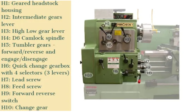
Bed:
It is the machine's foundation. It is built of a single piece of semi-steel casting (Chilled Cast Iron). The bed consists of two heavy metal slides running lengthwise, with ways or ‘V’ formed upon them and rigidly supported with cross girths.
• It is sufficiently robust to absorb vibration and has a good damping capability to prevent deflection caused by cutting forces.
• It supports the lathe machine's headstock, tailstock, carriage, and other components.
Tail Stock:
The tail stock is located above the lathe bed on the right side.
It's utilised to:
• Hold the long end of the job in place and prevent it from sagging.
• It retains the tool for various operations such as drilling, reaming, tapping, and so on.
• It's also utilised to offset the tailstock for a modest degree of taper on a long job.
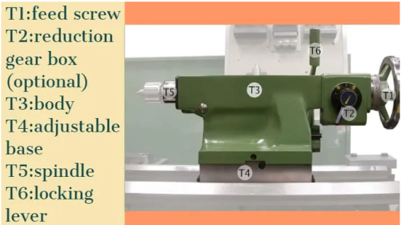
Carriage:
When the machining is finished, the carriage is utilised to support, guide, and feed the tool against the workpiece.
• It holds the cutting tool and moves and controls it.
• It provides the tool with sturdy support during operations.
• It uses an apron mechanism to transfer power from the feed rod to the cutting tool for longitudinal cross-feeding.
• With the help of a lead screw and half-nut mechanism, it makes thread cutting easier.
It consists of:
- Saddle
- Cross-slide
- Compound rest
- Tool post
- Apron
It provides three movements to the tool:
- Longitudinal feed-through carriage movement
- Cross feed-through cross slide movement
- Angular feed-through top slide movement
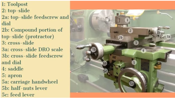
Saddle:
It is often formed of a ‘H' shaped casting with a ‘V' and a flat guide for placement on the lathe bed guideways.
Cross-slide:
It is attached to the saddle's top. The top surface of the cross-slide is provided with T-slot.
Tool post:
In its various settings, it supports the tool post and cutting tool. It can be swivelled in the horizontal plane to any desired position. It's required for drilling short tapers and turning angles.
It is the carriage's highest section, and it holds numerous cutting tools or tool holders.
There are three types of tool post commonly used and those are:
- Ring and rocker tool post
- Square head tool post
- Quick change tool post
Apron:
The feed mechanism is housed in an apron. It is attached to the saddle and hangs over the edge of the bed.
Lead screw:
A lead screw is also known as a translating screw or a power screw. It is a device that converts rotational motion into linear motion. In a lathe machine tool, a lead screw is used for thread cutting.
Feed Rod:
The carriage is moved from the left to the right, as well as from the right to the left, using the feed rod.
Chuck:
Chuck is accustomed to securely grasping the workpiece.
There are generally 2 types of chucks:
- Jaw self-centering chuck
- Jaw independent chuck
Main Spindle:
Long jobs can travel through the spindle, which has a hollow cylindrical shaft.
It is so well built that the cutting tool's thrust does not deflect the spindle.
Leg:
Legs are carrying and transferring the entire load of a lathe machine tool to the ground. The foundation bolt holds the legs firmly to the floor.
2.11.4 Schematic diagram of the lathe machine:
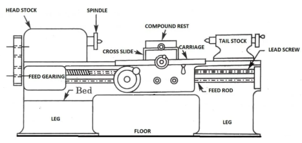
2.11.5 Types of Lathe Machine
A lathe machine tool is used to remove extra material from a workpiece in order to shape and size it to the desired form and size.
So, what are the many sorts of lathe machines? The following types of lathe machines have been identified:
• Engine or Center Lathe
• Capstan and Turret Lathe • Speed Lathe
• Lathe in the Tool Room
• Lathe on the Bench
• Lathe that works automatically
• Special Purpose (SP)
• CNC Milling Machine
Center or Engine Lathe Machine:
The most often used lathe machine is the centre or engine lathe machine, which may still be found in every workplace.
The operation like Turning, facing, grooving, Knurling, threading and more, such operations are performed on this type of machine.
The bed, saddle, headstock, and tailstock are all included in the engine lathe machine. An engine lathe's headstock is stiff, whereas the tailstock is movable and can be utilised to facilitate operations like knurling.
With the help of feed mechanisms, it can simply feed the cutting tool in both longitudinal and lateral orientations.
The gear or pulley mechanism is used to drive centre lathe machines.
Belt-driven, motor-driven, and gearhead-driven mechanisms are the three types of driven mechanisms available.
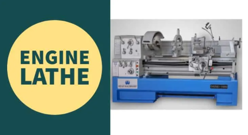
Speed Lathe:
Wood lathe is another name for speed lathe.
The machine operates at a high pace, as the name implies. The spindle in the headstock rotates at a very high speed. It has pieces like a headstock and a tailstock, but no feed mechanism like a centre or an engine lathe. We give a manually operated feed.
This machine rotated at speeds ranging from 1200 to 3600 RPM.
For spinning, centering, polishing, and cutting wood, a speed lathe is utilised.
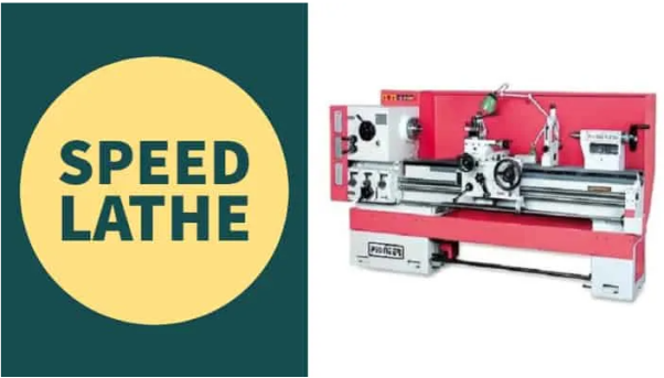
Capstan and Turret Lathe:
This is a manufacturing industry-advanced technology.
The capstan and turret lathe machine are a modified version of the engine lathe machine that is used for mass production (big quantities).
This machine is utilised in situations where the sequence of operations is done on the workpiece and no alternative operation is conducted.
These machines provided by hexagonal turret head instead of the tailstock in which multiple operations (Turning, facing, boring, reaming) performed in a sequence without changing its tool manually, after each operation the turret rotated.
It also includes three tool posts. It takes up more room on the floor than other lathe machines.
Capstan and turret lathes are only used for huge projects.
The fundamental benefit of employing a capstan and turret lathe is that even inexperienced operators can complete a task.
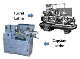
Tool Room Lathe:
The toolroom lathe machine has a maximum speed of 2500 revolutions per minute.
The parts are almost the same similar to engine lathe machine but the parts are built very accurately and should be arranged in proper sequence because this lathe is used for highly precious work with very fewer tolerances.
It is mostly utilised in grinding, tooling, dies, gauges, and machining tasks where precision is required.
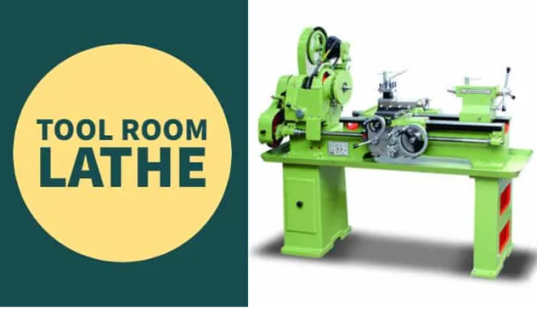
Bench Lathe:
The bench is where the bench lathe machines are mounted.
This type of lathe is compact in size and is used for very precise work. It contains all of the same components as an engine lathe and a speed lathe.
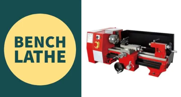
Automatic Lathe:
The term "automatic lathe" refers to a machine that conducts work automatically.
Standard lathes have various disadvantages, such as the fact that they are not suitable for large manufacturing. Automatic lathes, on the other hand, are employed in large production. The automation in it is due to a number of mechanisms.
The tool does not need to be changed manually in this case because it changes automatically.
The main benefit of having this machine is that a single operator can handle more than 4 to 5 machines at once.
These lathes are high-speed and heavy-duty machines.
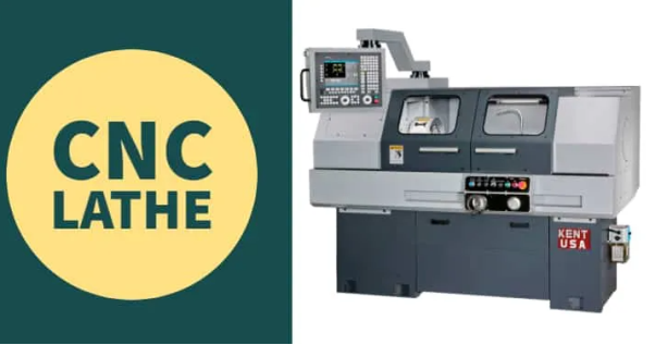
Special Purpose Lathe:
As the name implies, a "special purpose lathe" is a machine that performs operations that are not possible on conventional or other machines.
It is well-known for its high-volume manufacture of similar components.
Vertical lathes, wheel lathes, T-lathes, Multi Spindle lathes, Production lathes, Duplicate or tracer lathes, and so on are examples of unique lathes.
Journals and rail rods are machined on a wheel lathe. It's also used on locomotive wheels to turn the threads.
The "T -lathe" is used to machine jet engine rotors. In the shape of a T, the axis of the lathe bed is at right angles to the axis of the headstock spindle.
CNC Lathe Machine:
Computerized numerically controlled (CNC) is the abbreviation for computerised numerically controlled.
Because of its quick and precise operation, this is now commonly employed as a lathe. It is considered to be one of the more advanced varieties.
The machine tool is controlled by computer programmes. Once the programme is loaded into the computer, it begins to operate at a high rate and with great accuracy.
Even a pre-planned programmed machine exists, in which once the code for the various tasks is set, the machine may begin operating without having to change the code again.
After the initial setup, a semi-skilled worker may readily run it.
These sorts of lathes, like capstan and turret, are also utilised for mass manufacturing, but there is no programmed feeding system.
These lathes produce components with extremely tight dimensional tolerances.
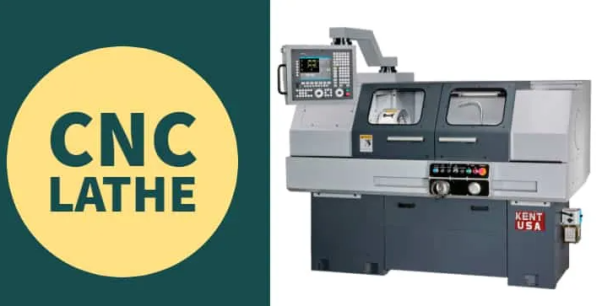
2.11.6 Operations performed in a Lathe
A Lathe Machine consists of the following operation:
- Centering
- Facing
- Turning
- Chamfering
- Knurling
- Thread cutting
- Drilling
- Boring
- Reaming
- Spinning
- Tapping
- Parting off
We must load the job and centre it on the head-stock spindle before proceeding with any lathe action.
In lathe operations, the task is held by the headstock spindle, which rotates at the same speed as the spindle. The carriage, in addition to holding the tool on the tool post, rotates the tool post longitudinally or transverse to provide the required feed on the work.
These two actions (longitudinally and crosswise) aid in the removal of metal chips and the formation of the job's right shape.
The lathe is so adaptable that it can even make another lathe.
Although we describe certain crucial lathe operations in detail, it's difficult to say which operations are not done in a lathe machine tool.
Centering operation in the lathe:
When the job must be held between two centres, we employ this operation to create a conical hole in the face of the job to serve as the bearing support of the lathe centre. (There are two types of stocks: headstock and tailstock.)
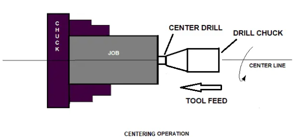
Facing operation in the lathe:
Facing operation is for making the ends of the job to produce a smooth flat surface with the axis of operation or a certain length of a job.
This surgery entails
1. Use a three or four-jaw chuck to hold the workpiece on the headstock spindle.
2. Rotate the task by starting the machine at the desired RPM.
3. Provide a desired feed in the perpendicular direction of the job's axis.
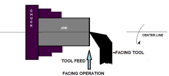
Turning operation in the lathe:
The process of removing surplus material from a workpiece in order to create a cone-shaped or cylindrical surface.
There are various different types of turning operations:
- Straight turning
- Shoulder turning
- Rough turning
- Finish turning
- Taper turning
- Eccentric turning
Straight turning:
This operation is done to produce a cylindrical surface by removing excess material from the workpiece.
It is done in the following ways:
1. Secure the job with a suitable work holding device and verify that the job axis is parallel to the lathe axis.
2. Place the cutting tool on the tool post with the cutting edge parallel to or slightly above the work axis.
3. Adjust the spindle to the desired feed rate.
4. Determine the depth of cut based on the finish or rough cut.
5. Begin the machining process.
6. Activate automatic feed to move the carriage with the tool to the required length, then deactivate the feed to return the carriage to its original position.
7. The procedure is continued till the task is completed.
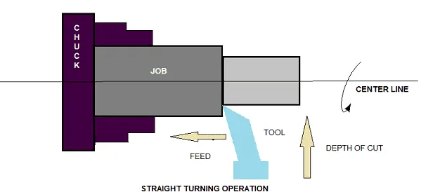
Shoulder turning:
A shoulder turning is called which has a different diameter to form a step from one diameter to another.
The shoulder is divided into four types.
Square
Bevelled
Radius
Undercut
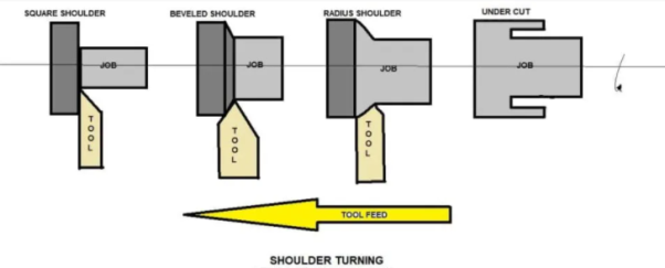
Shoulder Turning
Rough turning:
It is a process of removal of excess material from the workpiece in minimum time by applying a high rate of feed and heavy depth of cut.
The cut depth is 2 to 5mm, and the feed rate is 0.3 to 1.5mm each revolution.
Finish turning:
To achieve a smooth surface, the finish turning operation necessitates a high cutting speed, a low feed rate, and a very shallow depth of cut.
Finish turning has a cut depth of 0.5 to 1mm and a feed rate of 0.1 to 0.3 mm per revolution.

Taper turning:
A taper is described as a consistent drop or rise in a workpiece's diameter across its length.
Taper turning is the process of creating a conical surface with a steady reduction in diameter from a cylindrical object.
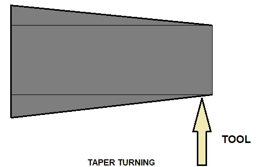
Taper turning methods:
Any of the following methods can be used to create a tapering form.
1. Using a form tool to turn the taper
2. The compound rest can be swivelled.
3. The process of resetting the tailstock
4. With the help of a taper turning attachment
Let me go over them briefly.
Taper turning by form tool:
It's used with a form tool or a broad nose tool to create a short length of taper.
Any increase in taper length necessitates the use of a broader cutting edge, which may cause the workpiece to be destroyed or spoiled owing to vibration.
The tool angle in this operation must be half of the taper angle.
Taper turning by swivelling the compound rest:
For turning step and short tapers, this procedure is utilised.
This is how it's done:
1. Swivel the compound rest off the center line of the lathe centre via a half taper angle.
2. Secure the carriage in position with a clamp.
3. The feed handle on the compound rest is used to complete the taper after the tool has been adjusted and fixed.
Tail-stock set over method:
The tail-stock is set over to half taper from its center-line.
Between the centres, there is a job. The workpiece's length will be sufficient. This procedure is used to create a slight taper on a long work.
It's solely used for external taper.
By taper turning attachment:
It is carried out in the following manners:
1. A hinder screw is used to liberate the cross slide from the lead screw.
2. A belt tightens the rear end of the cross slide with a guide block.
3. Angle the guide bar away from the lathe axis. (Half-angle taper)
4. The compound slide, which is at a right angle to the lathe axis, determines the required depth of cut.
Chamfering operation:
Chamfering is a process that involves beveling the end of a work to eliminate burrs, improve the appearance, and create a channel for the nut into the bolt.
After thread cutting, knurling, and rough turning, this process is performed.
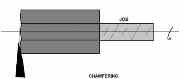
Knurling operation:
It is the technique of producing a rough surface on a workpiece so that it may be gripped effectively.
Knurling tool is held rigidly on the tool post and pressed against the rotating job so that leaving the exact facsimile of the tool on the surface of the job.
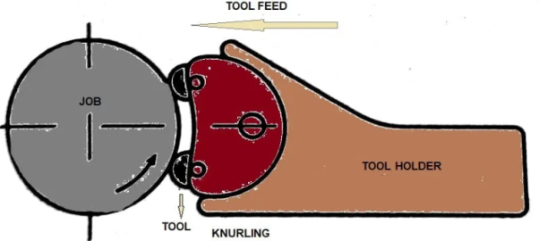
Thread cutting operation:
It's the process of feeding a tool longitudinally while the task revolves between two centres to create a helical groove on a cylindrical or conical surface.
Tool setting for thread cutting operation:
The tool should be placed to the height of the task's center line and at a 90-degree angle to the job.
Tool setting gauge is used for this purpose.
Feeding during thread cutting operation:
It can be accomplished in two ways.
1. Even if the tool is fed at a perfect 90-degree angle to the task axis, it will not have adequate cutting action since only the front end of the tool cuts.
2. The tool can be fed at a 27-30 degree angle with the compound rest set so that the entire side of the tool is utilised for cutting action, resulting in a better thread polish.
Job speed during threading:
In the turning operation, the job speed will be 1/3 to 1/4 of the normal job pace.
Drilling operation:
Drilling is a process that allows us to create holes in a task.
The task is turned on the lathe axis at the turning speed, with the drilling tool mounted on the tail-stock spindle. Hand feed is used to move the tail-stock towards the work.
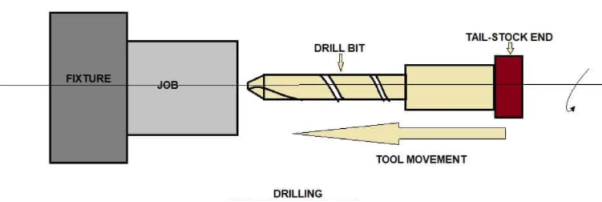
Boring operation:
In this operation, we can enlarge the diameter of the existing hole on a job by turning inside with some farm tool known as a boring tool.
The tail-stock is also equipped with a boring tool.
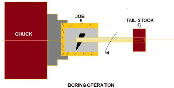
Reaming operation:
Reaming is the operation for sizing or finishing a drilled hole to the required size by a tool called reamer.
The tool is attached to the tail-stock.

Spinning operation:
The sheet metal job is held between the former and the tail-stock centre rotates at high speed with the former in this operation.
The job is pressed on the periphery of the former by a long round nose forming tool tightly fastened on a specific tool post. As a result, the work has taken on the precise shape of the previous one.
This is a no-chip machining method.
Tapping operation:
Using a tool called a tap, we employ this procedure to create internal threads within a hole.
Three taps are generally used in an internal thread.
- Taper Tap
- Second Tap
- Plug Tap
Parting-off operation:
After the machining process is completed, it is the procedure of cutting off a bar type job.
A bar type job is held in a chuck and rotated at turning speed while a splitting off tool is slowly fed into the job until it reaches the job's centre.
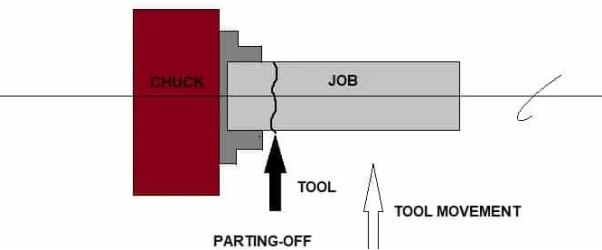
2.11.7 Specification of a Lathe:
A Lathe is generally specified by:
1. Swing- the lathe bed's biggest work diameter that can be swung.
2. The distance between the centre of the headstock and the centre of the tailstock.
3. The bed's length in metres.
The pitch of the lead screw is number four.
5. The machine's horsepower.
6. HS spindle speed range and number of speeds
7. The tonnage weight of the machine.
2.11.8 Transfer Machines:
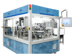
Metalworking machine tools having multiple stations for executing diverse machining processes are known as transfer machines. Workpieces are loaded into the machine and indexed from station to station automatically. Each station conducts a distinct operation on the workpiece at the same time, and they leave the machine as a partially or fully finished unit. Multiple, sequential mechanical components, such as cutting heads, transfer devices, indexing tables, and work, make up standard transfer machine systems. Workpieces are indexed in a circular or linear path using stationary or mobile fixtures. Components flow through each work station during a cycle, performing particular machining procedures. The indexing table can move both continuously and intermittently and can turn vertically or horizontally. Transfer machines boost production rates when used in conjunction with an automated transfer line for part feeding.
Mass production of metal parts for a range of industries, such as the automotive and industrial machinery industries, is one application for transfer machines. For the production of discrete components, custom systems are available.
Types:
There are three primary types of transfer machines:
Rotary: Workpieces are moved between stations in a circular path by these machines. These systems are cost-effective because they can be mass-produced in a compact space. Due to lower labour costs, modern CNC-enabled flexible transfer machines of this type have gained appeal in European and North American domestic production facilities.
In-line or linear: Workpieces travel in a straight line from one workstation to the next. The number of axes a machine operates on, combined with the number of machining stations, determines the quantity and type of parts and processes the machine can perform.
Trunnion: The trunnion is a horizontal shaft that is used to index parts. The pieces rotate in a rotational manner similar to that of a Ferris wheel. Cutting tools simultaneously engage the pieces at their various stations, allowing each index to yield a finished item. The number of machining units is determined by the machine's size.
Secondary procedures, as well as associated tooling and manpower, are eliminated with CNC-enabled trunnions with the ability to alter their tooling. Newer trunnion transfer devices can process a workpiece axially on both ends. They can be fitted with vertical or angular supplemental tooling components to create a five-sided contact with the component during the machining process.
Applications
Transfer machines are used for a variety of tasks, including:
• Pneumatic fittings
• Hydraulic fittings
• Automotive
• Made of cast iron
• Aluminium
• Flanges
• Forgings
• Castings
• High-volume production
• Manufacturing with a medium volume
Selection
With a cost per transfer machine of $1,000,000 or more, the predicted yield must be examined to ensure that the investment is justified. Historically, transfer machine tool integration was considered at production levels of one million or more pieces. Today, advanced machining mechanisms incorporate computer aided vision systems, superior material handling technologies and other innovations. These tools can produce significantly smaller volumes, with a minimum of 200,000 units, while keeping production costs and time under control.
These systems are not a one-size-fits-all solution; they can be custom engineered for specific applications. They also have the ability to run constantly, resulting in a higher return on investment than comparable devices or processes. A transfer machine's customization possibilities are a significant aspect.
References:
- Fundamentals of Machining and Machine Tools, G.Boothroyd and W.A.Knight, CRC Press
- Metal Cutting Principles, M.C.Shaw, Oxford University Press
- Metal Cutting Theory and Practice, A.Bhattacharya, Central Book Publishers
- Manufacturing Technology – by P.N.Rao, Tata McGraw Hill publication.
- Modern Manufacturing Processes, P.C.Pandey, H.S.Shan, Tata McGraw Hill