Unit – 3
Ceramic matrix composites
3.1.1 Introduction to Ceramic matrix composites
Spinning continuous yarns, after producing and controlling fire and inventing the wheel, is possibly mankind's most crucial development, allowing him to thrive outside of tropical temperature zones and spread across the Earth's surface. In comparison to animal skins, flexible fabrics composed of locally grown and spun fibres like as cotton, flax, and jute were a huge step ahead. As more natural materials were employed, the earliest composites emerged, including straw-reinforced walls, bows (Figure M1.1.1 (a)), and chariots built of glued layers of wood, bone, and horn. These historical composites were quickly superseded by more lasting materials such as wood and metal.
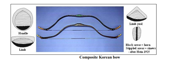
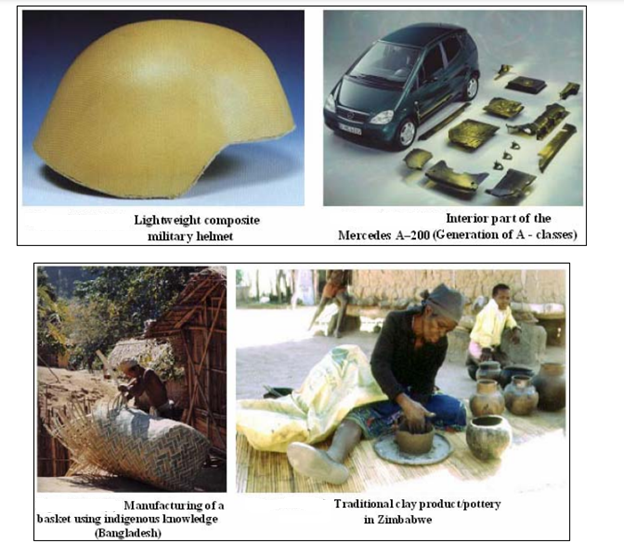
Originating in early agrarian cultures and nearly forgotten for centuries, the use of lightweight composite constructions for numerous technical solutions began to see a significant rebirth in the second half of the twentieth century. Using composites to improve the structural performance of spacecraft and military aircraft became popular in the latter two decades of the previous century, when they were mostly utilised for their electromagnetic qualities (insulators and radar-domes). First and foremost, with the development of superior materials at growing costs, today's major technology drivers are cost reduction during manufacture and operation. The use of composites to protect people from fire and impact (Figure M1.1.1 (b)) is a recent development, as is a trend toward more environmentally friendly design, which has led to the reintroduction of natural fibres into composite technology (see Figure M1.1.1) (c). The accessibility and reproducibility of the applied production techniques are increasingly determining the success of composites in applications, both in terms of volume and quantity. Figure M1.1.1 (d) and Figure M1.1.1 (e) demonstrate several examples of natural fibre use (e).
3.1.2 Monolithic material properties
Monolithic materials in the form of discs, stacked layers, rolled sheets, sponges, irregular chunks, tubes, and cylinders have all been proved satisfactorily over the last decade. Natural polymers, such as cellulose, synthetic polymers, such as porous styrene-, methacrylate-, and acrylamide-based polymers, and inorganic materials, primarily silica, were used to create these formats. From the standpoint of both preparation and application, each technique is intriguing.
Although there are many recent publications and patents on monolithic separation media, the knowledge is dispersed among a large number of periodicals. As a result, this book answers a market need for a thorough reference book on the subject.
Monolithic materials covers all current monolithic material types and provides a holistic picture of this innovative separation media structure. The hydrodynamics of the system and mass transfer differ significantly from those determined for packed columns because the flow pattern in monolithic devices differs from that in packed beds. As a result, this volume includes contributions on both flow and mass transfer in monolithic materials. The book devotes a substantial percentage of its content to monolithic material applications. It also informs the reader on the origins of the materials in question, as well as their qualities and potential applications.
3.1.3 Key Features
• Monolithic materials are currently very popular within several scientific areas such as chromatography, optics, catalysis, diagnostics, genomics, proteomics, and microfluidics.
• Provides useful information on the origins of various materials, as well as their qualities and their applications.
Key takeaways:
• As with traditional ceramics, a strong link would necessitate a high elongation capability of the fibre bridging the crack, resulting in a brittle fracture. The creation of high-crack-resistance CMC material necessitates a procedure that weakens the link between the fibres and the matrix.
•Chemical vapour or liquid phase infiltration, polymer infiltration and pyrolysis (PIP), and hot press sintering techniques are the most common methods for making CMCs.
The ceramic matrix in PIP is created by infiltrating a fluid into the fibre reinforcement.
3.2.1 Definition
Since their accidental discovery in 1953, glass-ceramics have piqued the interest of both academics and industry due to their unusual combination of sintered ceramic qualities and the distinguishing qualities of glasses.
3.2.2 Introduction
Glass-ceramics have been widely used in a variety of fields in our daily lives to date. Glass-ceramics are used in five distinct industries, including building, optical, military, biomedical, electronic, and kitchenware, according to the Wikipedia. In the meantime, the qualities of glass-ceramics that allow them to be used in the aforementioned sectors have been detailed.
3.2.3 Properties and Applications
Construction Application
There has been a lot of research on making glass-ceramics from silicate waste, such as coal combustion ash, slag from steel manufacturing, fly ash and filter dusts from waste incinerators, mud from metal hydrometallurgy, and so on, in the previous few decades. These low-cost glass-ceramics made from silicate waste from industry are often robust, rigid, and chemically resistant. Abrasion and chemically resistant parts, as well as floor and wall tile, are among its intended applications. Neopariés LT, a glass–ceramic containing wollastonite as the predominant crystalline phase, is one of the most widely utilised in construction. Glass–ceramic panels from Neopariés are a great alternative to stone for both indoor and exterior applications.
Optical Application
Because zero porosity can be attained relatively readily, many glass–ceramics exhibit excellent translucency or even transparency in the optical field. Glass–ceramics are therefore a great material for optical applications. For example, telescope mirror blanks and laser gyroscopes have been made from clear and low thermal expansion glass–ceramics based on the lithium aluminosilicate (LAS) system [3]. Glass-ceramics have optical qualities that are similar to those of single crystals, but they are more cost effective and better suited to making larger things with intricate shapes. Furthermore, transition metal ion doped glass-ceramics have been created for usage in broadband optical amplification, tunable and infrared lasers, phosphor with tunable UV/blue luminescence characteristic, and solar collectors[4][5].
Military Application
Glass–ceramics are being employed in the nosecones of high–performance aircraft and missiles in the military. To resist critical circumstances resulting from high–speed flying in the environment, materials utilised in these applications must have a difficult mix of properties: Low thermal expansion coefficient; strong mechanical strength; strong abrasion resistance; strong navigational radar wave transparency[6][7]. However, little has been published and patented on the chemical composition, microstructure, and preparation processes of the glass-ceramics used for military, because of the sensitive nature of this military-related research. No glass, metal or single crystal can simultaneously meet all of these relevant specifications, while glass–ceramics with the tailored properties were able to achieve the challenge. Another example is the view-window for armoured vehicles or tanks, which requires the view-window material to be both strong and transparent. High-strength, high-toughness, and high-translucency glass-ceramics are great options for these applications.
Medical Application
Bioglass has been effectively employed in the medical industry, for example the “gold standard” bioglass 45S5 created by Larry Hench[8]. The intrinsic low strength and toughness of bioglass, however, limits its use as a load-bearing biomaterial. Glass–ceramics address the weakness of bioglass by using crystalline phases as reinforcing and toughening phases. Furthermore, because glass-ceramics contain a glass phase, they have higher bioactivity and biocompatibility than sintered ceramics. For example, the most noteworthy bioactive glass–ceramic for hard tissue healing is A–W glass–ceramic, which comprises apatite and –wollastonite (CaO•SiO2) crystals (with the commercial brand name Cerabone). Research on improving the properties of glass-ceramic biomaterials is still ongoing, and one direction is to introduce greater multifunctionality to glass-ceramics through inorganic modifications. For example, by incorporating specific ions such as Cu2+, Sr2+, and Zn2+ ions, bioactivity and antimicrobial activity can be simultaneously enhanced[10].
Electronic Application
All–solid–state secondary batteries with inorganic solid electrolytes are predicted to be the next–generation high–output batteries in the electronic area. High ionic conductivity and good formability are critical characteristics for appropriate solid electrolytes. Glass–ceramics have been used to create a variety of inorganic solid electrolytes. For example, glass–ceramics with the crystalline form of Li1+x+yAlxTi2xSiyP3yO12 displayed a high lithium–ion conductivity of 103 S•cm1. Solid electrolytes composed of glass-ceramics are more stable in the open atmosphere and even when exposed to wet air than liquid electrolytes, hence they are predicted to be used for a variety of applications[12].
Kitchenware Application
In kitchenware field, higher toughness (compared with glass), appealing aesthetics, and very low thermal expansion coefficient make glass–ceramics the excellent material for kitchenware, such as cooktops, cookware, and bakeware. Corning pioneered the notion of cooking on a smooth white glass-ceramic surface in the late 1960s. Many glass-ceramics of various compositions have been developed for use as kitchenwares to date. The Li2O–Al2O3–SiO2 (LAS) combination is the most extensively utilised, with other components such as CaO, MgO, and ZnO[7]. The predominant crystalline phase is a solid solution of –quartz with a negative CTE. LAS glass–ceramics can withstand repeated and rapid temperature fluctuations between 800 and 1000 degrees Celsius.
3.3.1 Processing of ceramics
Ceramics are inorganic, nonmetallic substances that are treated to high temperatures in order to be used in manufacturing. I spoke about the term “traditional ceramics” which will be the focus of this post, it refers to ceramic products that are produced from unrefined clay and combinations of refined clay and powdered or granulated non-plastic minerals – i.e. pottery/stoneware/chinaware/porcelain/etc. The ceramic substance must go through the traditional manufacturing process to create these final products, which is as follows:
Step #1: Milling & Raw Material Procurement – The raw materials used in the process include milled materials that are often found in mining sites and have been reduced in size from large to small or even pulverised depending on the end result. The goal is to remove any impurities in the components so that they may be mixed and formed more easily, resulting in a more reactive substance when fired.
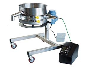
Step #2: Sizing – Remember how I said vibration would play a role? It's finally here! The materials that have been milled and procured must be sized during this step in the processing cycle to differentiate usable material from non-usable material. The effect of managing the particle size is proper bonding and a smooth surface on the completed product. When dealing with dry, fine powder mixtures in ceramics, Fine Mesh Vibratory Sifting Equipment such as our HK Single Motor Sifter can help. Mesh sizes come in a variety of sizes. The size of the screen deck is determined by the thickness of the slurry and the proportion of solids in the mix. We've also supplied bigger-scale screeners to Ceramics companies, such as our model EMS Electromechanical Screener, which has a higher load capacity and works well when the slurry contains larger particles of material.
We were contacted by a customer who needed a vibratory solution for their ceramics processing. Insulating fire bricks for industrial purposes were created by the business. After the bricks had been crushed, they intended to remove the rejects or larger regrind bricks. They were able to consolidate the valuable elements and recycle them for the following batch of bricks by using Cleveland Vibrator's Vibratory Screener.
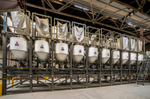
Step #3: Batching – This step of the process is also known as "blending," and it involves calculating numbers, weighing, and mixing the raw materials for the first time. Vibratory Feeders can be used to ensure continuous material flow into a pub mill hopper. CF-A Air Powered Feeders are a wonderful solution if you have a light load capacity and a dusty hazardous environment. It is not, however, as versatile as the EMF Electromechanical Feeder, which can deliver a wide range of pressures and frequencies. Despite the fact that EMF Models are not normally utilised in dusty or dangerous areas, they can be equipped with explosion-proof Rotary Electric Vibrators to manage a greater load capacity.
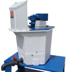
Step #4: Mixing – Prior to forming, the ingredients of the ceramic powder are mixed or blunged together to create a more chemically and physically homogeneous material. When working with dry mixes, pug mills are frequently the chosen piece of machinery. It is also necessary to include binders or plasticizers. A filter press would separate the water from wet slurry combinations and yield the clay body from the mix. To improve the processing of the ingredients, deflocculants and antifoaming agents are added to these wet combinations.
Step #5: Forming – Materials including dry powders, pastes, and slurries are consolidated and moulded in this stage to create a cohesive body for whatever end product is needed. Vibratory compaction can be utilised to achieve the desired shape in the case of dry forming. Vibratory Jogger Tables may be preferred for moulds of a smaller scale with a low weight, however FA Flat Deck Vibratory Tables can be employed in circumstances when the mould is huge. The weight of the mold/materials and the scale of the mould should make selecting a suitable vibratory compaction table very simple.
Step #6: Drying – The produced materials keep water and binder in their mix, which might cause the result to shrink, warp, or deform. Convection drying, in which warm air is circulated around the ceramic item to reduce the chance of such flaws in the final product, is the most often employed method.
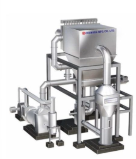
Step #7: Glazing – This stage is added to the process prior to fire, as it is in traditional ceramics. The glaze is usually made of of oxides that give the product the desired finish. A ball mill or an attrition mill is used to grind the raw materials. Customers have received Vibratory Screeners, which screened the glaze to give it a uniform consistency that would be smooth and even when applied on the pottery. Spraying or dipping procedures can be used to apply the glaze.
Step #8: Firing – The ceramics go through a controlled heat process called sintering or densification, in which the oxides are cemented into a dense, cohesive mass made up of uniform grain. Some general considerations for several sorts of firing end products:
1. A short firing time results in a porous, low-density end product.
2. Fine-grained, high-strength products result from a short – intermediate firing time.
3. A long firing time results in a coarse-grained, creep-resistant product, which implies the material will not distort if loaded for an extended period of time.
Key takeaways:
• Typically, ceramics are made by applying heat to processed clays and other natural raw materials to create a stiff product.
• Extrusion, slip casting, pressing, tape casting, and injection moulding are some of the most frequent forming procedures for ceramics.
• 2 List the basic procedures involved in traditional pottery processing. The steps are: (1) raw material preparation, (2) shape, (3) drying, and (4) fire.
3.4.1 Cold pressing
When it comes to producing shaped components, powder processing is typically a more appealing option than casting or deformation processing. It is the only realistic alternative in many cases, such as when the material is difficult to melt, confine, or distort. The powder is mixed with a fugitive (typically polymeric) binder and moulded into the desired shape, often by merely applying pressure to a flexible (rubber) mould storing the mixture at room temperature. The resulting "green compact" is then burned at a high temperature (typically considerably below the material's melting temperature), causing the binder to be driven off and the compact to sinter - see below. Although "sintering aids" are occasionally included, the powder can be only one species.
Because sintering frequently necessitates substantial diffusion, the temperature must be relatively high (>0.6Tm). The ensuing reduction in surface area drives diffusion. Diffusion tends to lessen the local curvature of the free surface on a local scale. This is seen in the diagram below, where diffusion can take place either inside the surface or "internally" - that is, within the lattice or via favoured routes such grain boundaries or dislocations. This diagram emphasises a crucial point: whereas both modes of diffusion drive the formation of necks (through material transport to regions of high surface curvature), increasing the compact's strength, only internal diffusion causes densification (ie movement of the centres of particles towards each other). Strong compacts with somewhat high porosity levels are sometimes desirable (eg for lubricated bearings). In these circumstances, circumstances that favour surface diffusion over interior diffusion are sought.
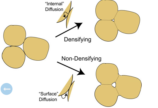
The animation below depicts a schematic representation of the mould filling, cold pressing, and diffusion processes that generate neck growth (with or without densification). The process variants of liquid phase sintering, reactive sintering, and hot isostatic pressing are also depicted (HIP).
3.4.2 Sintering
Time, temperature, and furnace environment are the primary variables that define a powder sintering operation. Sintering temperature is typically.7 to.9 of the melting point of the powder. The length of time it takes to sinter depends on the production technique and the material used. Sintered tungsten, for example, is sintered for a long time. Standard industrial powder sintering periods range from 8 minutes to 10 hours, depending on the technique and material.
During powder sintering, a regulated environment is essential. Controlling carburization and decarburization, preventing oxidation and removing existing oxides, preventing undesirable chemical reactions, and assisting in the burning off of additives are all goals of the atmosphere in sintering. Carbon monoxide, disassociated ammonia, hydrogen, partially combusted natural gas, and inert gases like as argon or helium are common atmospheres used in industrial powder operations. Parts are sometimes sintered in a vacuum as well. Refractory metals and stainless steel are the most common materials for vacuum sintering.
There are three phases to the sintering of a green compact. Preheating the powder compact is the first step. The part will be preheated to a relatively low temperature, allowing additives to be burned off. Preheating will also begin to strengthen the part's bonding, ensuring its integrity for the next stage. In the second stage, the temperature is raised to the sintering temperature and held there for a set period of time to achieve the desired quantity of bonding. During the third step, the temperature is reduced as the part is allowed to cool. It's vital to keep the work in the controlled furnace environment during cool down to avoid undesirable chemical reactions between the part and the environment.
Batch and continuous furnaces are used in the production of industrial powders. Low amounts of items are placed in a batch furnace, where they undergo the whole sintering process before being removed. Continuous furnaces have three zones for the three steps of the manufacturing process, allowing for continuous production (preheat, sinter, and cool down). A continual supply of parts is carried through the chambers on a moving belt. Heat doors can open and close quickly to allow parts to pass through while keeping the heat within. The belt moves at a precise speed to ensure that pieces spend the appropriate amount of time in each chamber. Continuous furnaces are the most popular alternative for powder sintering due to their consistent results and high output rates. Batch operated furnaces have a lower output rate and are utilised less frequently, but they provide better control of the environment and thus part quality. Batch furnaces are the only way to get a vacuum atmosphere.
• HIP, or Hot Isostatic Pressing, is a material processing technique that compresses materials by simultaneously applying a high temperature of several hundreds to 2000°C and isostatic pressure of several tens to 200MPa. The most common pressure medium is argon.
HIP and hot pressing are extremely similar. Milling, forging, and extrusion all use high temperatures and pressures, but unlike HIP, they do not use isostatic pressure.
The effects of varied applied pressure conditions on the fabrication of high-density bismuth germanate (Bi3Ge4O12) ceramic scintillators by uniaxial hot pressing were examined. The sintering technique was able to eradicate the undesired secondary phase present in the nonsintered samples, according to X-ray diffraction. For samples sintered at pressures of 0.14 and 0.18 MPa, the height changes from samples with greater applied pressure rate and applied pressure duration result in a better relative density value of >95 percent. The radioluminescence results revealed that all samples exhibit the typical Bi3Ge4O12 emission spectra, with hot-pressed samples having a greater radioluminescence emission efficiency.
Eulytite crystals, such as bismuth germanate (Bi4Ge3O12, BGO), are important because of their unique properties, such as high light output, quick luminescent decay time, low afterglow, and good radiation durability. Other features of the BGO include a high effective atomic number (Zeff = 74), which promotes good ionising radiation attenuation, low hygroscopicity, and high density (= 7.1 g•cm3). These properties make them a significant material for scintillation applications like as positron detection, calorimetry, PET, and fusion controllers, all of which used single crystals.
The procedure of growing BGO crystals is not cheap. However, when compared to single crystal ceramics, polycrystalline ceramics have several advantages, such as quicker preparation and cheaper production costs. The sintering process is an experimental approach for producing polycrystalline ceramic bodies that is critical to the development of high-density ceramics. Hot pressing, spark plasma, microwave, and laser sintering are just a few of the sintering techniques that give good relative density values. The hot pressing technique is a simple one in which the sample is heated under a uniaxial or isostatic mechanical load, and the added energy speeds up the densification kinetics.
We previously demonstrated that the light output of sintered BGO ceramics when exposed to X-ray photons is substantially higher than that of single crystal form. We investigated the luminescence of BGO ceramics prepared by uniaxial hot pressing sintering and investigated its luminescence when exposed to an X-ray source in this paper. X-ray diffraction was used to examine the crystalline structure of ceramic powder and sintered samples. The effects of different sintering circumstances, such as load rate and uniaxial pressure load, on the relative density of sintered samples and their correlations with scintillating efficiency, were examined.
3.6.1 Chemical reaction bonding
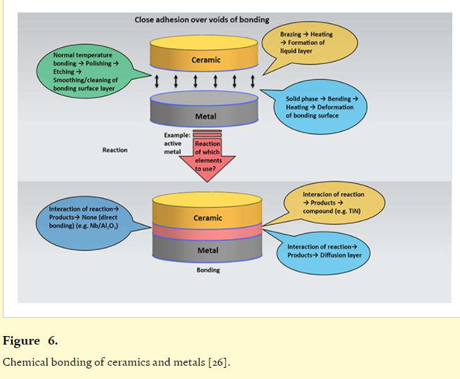
Bonding is generated by diffusion or chemical reactions when mass is transferred across the interface. Chemical interactions at the contact result in the creation of interfacial reaction layers that differ from both ceramic and metal characteristics [5]. Thick reaction layers increase volume mismatch stresses and thermal residual stresses, which are detrimental to joint strength. This can have a positive effect on joint quality by increasing the initial wettability of the metal on ceramic surfaces; however, thick reaction layers increase volume mismatch stresses and thermal residual stresses, which are detrimental to joint strength. Chemical bonding methods and procedures are depicted schematically in Figure 6. Brazing, for example, is a joining technique that involves bringing the irregularities and gaps that occur on the work's surfaces into a state of near cohesiveness using a liquid phase. Solid-phase joining also includes good adherence, which is achieved through heating, pressurisation, and distortion that occurs through work surfaces, as well as the interdependence of natural temperature, which appears to be direct contact for a period ranging between work surfaces through settlement and activation. It entails the creation of normal temperature tension threads in order to construct a full-contact interface between these materials using an energy source other than thermal energy and to establish a joint in the interface near its normal temperature.
The chemical potential of the atomic species involved is the driving force for a chemical reaction. If only the interaction of the metal with non-metallic elements of the ceramic is considered, chemical reaction is unlikely in many systems. When all of the various reaction potentials are taken into account, a net negative free energy can be obtained, indicating that the chemical reaction is thermodynamically favourable. Thermodynamic equilibrium can be used to forecast probable reactions at the contact. When there are more than three elements in a ceramic-metal combination, however, using the phase diagram to forecast all probable reactions is almost impossible. Furthermore, kinetics for which data is not readily available for ceramic-metal contacts limit the scope and possibilities of the reaction [30].
At low stress, reaction phases such as brittle intermetallics and solid solutions frequently cause interfacial failure [5]. Increased bonding temperature and time often boost chemical reactions and result in the production of thick reaction layers, which can reduce joint strength. Controlling bonding conditions at interfaces where planar reaction layers form is typically used to improve layer thickness and prevent interfacial debonding or brittle interfacial fracture along the reaction layer. The expansion of the reaction layer is reported to follow a parabolic rate curve in many ceramic-metal systems. The reaction product is found to have a coherent interface when bound to the ceramic.
3.7.1 Slurry Supply Mechanism
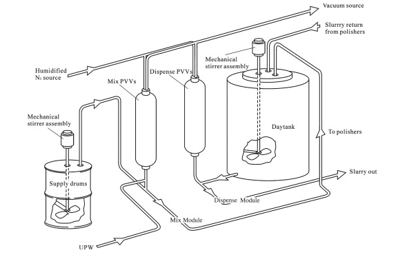
The slurry delivery system has a direct impact on the CMP process quality. If the slurry isn't correctly handled and supplied, for example, particles in it clump together and cause machining errors. The supply of slurry is managed during CMP of oxidised films so that it does not dry up, as this causes machining issues. The concentration of oxide in the CMP of metals should be kept constant, and drying and precipitation of the slurry should be prevented.
Vacuum/pressure or a pump can be used to deliver slurry. Both systems circulate slurry through a slurry pipe to the machining system. It is believed that the slurry will come into touch with valves, orifices, pipes, vacuum, or N2 gas and stay there while the machine is rotating over, hence steps should be made to ensure that the slurry supply is constant. One example of a slurry supply system is shown in Figure 4
3.7.2 Slurry sampling
Slurries for electrothermal vaporizers and atomizers are made by adding a liquid diluent to a solid material that has been crushed, sieved (if necessary), weighed, and stored in a container that ensures the slurry's stability for the sample period. The amount of solid material to weigh is determined by the analyte concentration and dilution in the final slurry volume. When the slurry is formed from more sample, the precision is improved for less homogeneous samples. The slurry sub-sample is manually placed into the atomizer, or with the help of an autosampler or a flow injection device. When solid material is weighed using autosampler cups, the maximum volume of slurry is limited to the cup volume (approximately 2 ml), limiting the amount of material that can be suspended. After the slurry is made, the solid sample must be equally distributed throughout the liquid volume.
Slurry sampling gained popularity in the 1990s as a method for dealing with a variety of samples, with advantages over other methods such as the ability to use conventional liquid autosamplers, perform multiple replicates in a single aliquot, handle larger amounts of sample, and change the slurry concentration. Improved analytical performance as a result of the combined benefits of solid and liquid sampling, as well as increased repeatability and reproducibility, are additional advantages. The enormous number of variables to consider, on the other hand, makes optimising analytical techniques utilising slurry sampling more difficult.
3.7.3 Slurry Flow
Positive displacement slurry pumps are used to pump the hot feed slurry into the autoclave (Geho, 2011). The autoclave's feed pressure is higher than the operating pressure, which is at 40 bar.
As depicted in Figure 11, the slurry then flows from left to right.
2 through 6 stirred chambers (over partitions) in the direction of the leached slurry outflow pipe To leach the concentrate and heat the slurry, sulfuric acid and steam are added to each chamber.
Finally, the leached slurry is driven out of the autoclave through the exit pipe by autoclave pressure. A choke valve modulates the exit flow rate and controls the slurry level in the autoclave.
The average slurry residence duration is one to two hours, resulting in a leaching efficiency of about 95% for nickel and cobalt.
3.7.4 Flow Digestion of Slurries
Slurries—solid sample suspensions in digestion acid—are a common approach to get solid samples into flow digestion systems. To achieve representative sampling, slurries should be stirred prior to entry into the flow system using magnetic stirring [62] or sonication.
In most cases, up to 1–4% solids (m/v) in the slurry are used. Higher mass fractions tend to clog narrow bore tubes or small apertures inside the switching plates of medium- and high-pressure systems' switching valves [62].
To avoid dilution of the digestion mixture by the carrier solution, it was also found helpful [72,75] to “embed” the sample within two acid segments, as shown in Figure 9.7.

Figure. Embedding the slurry within two acid segments.
3.7.5 Slurry Cementation
Commercially available slurry-based diffusion coatings have chemistries that are similar to those found in traditional pack cementation aluminide coatings. The coating components and halide activator are mixed together as a slurry or particle-loaded paint system, employing either an organic binder or a water-based emulsion in slurry cementation. At or near room temperature, the slurry/paint system can be dipped or sprayed onto the part to be coated. A low-temperature heat treatment, typically approximately 200 °C, cures the slurry spray onto the component. Depending on the final service conditions, the cured pre-diffusion coating may contain simply aluminium, aluminium + chromium, aluminium + silicon, or aluminium + chromium + silicon. After the binder, activator, and reactive metals overlay has been built up, the aluminium, silicon, and other additions are diffused into the substrate by heating the precoated parts in a furnace at temperatures ranging from 650 to 1100 °C, depending on the substrate to be coated and its intended use. The temperature is set so that the coating material in the slurry reacts with the substrate and interdiffuses to generate the final intermetallic coating. The reaction temperatures and chemistries are similar to those used in halide-activated slurry systems for pack cementation. Diffusion happens when the molten aluminium or aluminum-silicon particles in the precured cement come into direct contact with the substrate to be coated in systems without halide activation.
Sermatech was a pioneer in this field, with SermaLoy J (Figure 8) - one of the first widely used slurry aluminide coatings – offering exceptional resistance to type II hot corrosion. This slurry aluminide coating generates a silicon-enriched outer layer in -NiAl that protects against oxidation and corrosion up to 1000 degrees Celsius. As engine technologies advanced and directional solidified or single-crystal alloys became more widely used, less chromium was available within the alloy to form CrSi2 (a critical phase within SermaLoy J); thus, Sermatech and Rolls Royce collaborated to develop SermaLoy 1515, a multilayered structure slurry aluminide coating containing CrSi2 bands. Low-chromium-containing single-crystal alloys can benefit from this variant's hot corrosion prevention. Other slurry aluminide process versions, such as IP1041 produced by Indestructible Paints in the UK and Ceral 10 created by BWD Turbines Ltd, are now commercially available. Prior to heat treatment and reaction to generate the Si-containing aluminide coating, the latter uses a water-based slurry technique to apply the prediffused overlay layer. Slurry aluminide coating methods have recently been investigated as a possible method for providing oxidation protection of Fe–Cr ferritic steels for steam power plants, where the ability to form an iron aluminium oxidation-resistant coating at temperatures as low as 650 °C, combined with the ability to coat large steam turbine components at reasonable costs, makes the process commercially viable.
3.8.1 Matrix transfer moulding
All composite manufacturing procedures in which a liquid state matrix material (e.g. Epoxy resin) is pressed into a dry prepared reinforcing material are referred to as liquid composite moulding (e.g. Carbon fibre fabric). As the resin propagates between the fibre bundles and fibres, the major goal is to achieve full impregnation. The pressure difference is usually the driving force for impregnation. Positive operating pressures are used in resin transfer moulding (RTM), but the pressure in vacuum infusion is lower than atmospheric pressure. Vacuum assisted resin transfer moulding (VARTM) uses positive injection pressures while maintaining a vacuum in the mould cavity. Positive operating pressure approaches necessitate matched moulding (two or more part moulds), whereas vacuum infusion is typically accomplished on the mould using a flexible membrane (e.g. Polymer foil).
Our organisation handles the entire spectrum of liquid composite moulding procedures. From raw material analysis to process modelling and component manufacture, we provide solutions.
3.8.2 Raw material characterization
To understand the impact of resin and reinforcing materials on the impregnation process, both should be described. It is possible to measure resin qualities such as viscosity build-up or the degree of conversion over time at various temperatures. Permeability at varied fibre content ratios, geometrical distortion degree, and/or stacking sequence are all characteristics of reinforcement materials (e.g. with flow enhancing layers).
3.8.3 Process modelling
We are able to model and optimize the whole liquid moulding process with the help of the PAM-RTM software, in which the whole liquid molding processing chain is included. In a 3D simulation environment, reinforcement preforming, mould filling, and curing can all be reproduced. In a virtual environment, the measured resin and reinforcement properties can be immediately implemented, and process optimization can be done.
3.8.4 Component manufacturing
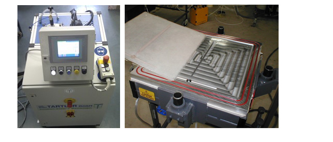
AAC can make resin transfer moulding (RTM), vacuum aided RTM, and vacuum infusion samples and components. Our mobile injection equipment (Tartler GmbH injection system) can handle a wide range of thermoset resins. It is possible to do resin injections at increased temperatures (up to 130°C) with continuous flow rates (0-0.5 l/min) or constant pressures (up to 90 bar). The flow rate, temperatures, and pressures may all be monitored in real time, allowing the conclusions of the process modelling to be verified.
3.8.5 Mould and Injection characteristics:
- Size: 40 cm x 40 cm
- Maximal curing temperature: 180 °C
- Injection for 1K system: up to 0.5 l/min
- Maximal pressure: up to 90 bars
- Volume: 5 Liters pre-mixed resin-hardener
3.9.1 Liquid Silicon Infiltration
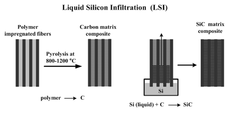
The Liquid Silicon Infiltration (LSI) process is a type of Reactive Melt Infiltration (RMI) technique in which the ceramic matrix is formed by a chemical reaction between the liquid metal infiltrated into a porous reinforcing preform and the substance (either solid or gaseous) surrounding the melt.
Silicon carbide (SiC) matrix composites are made via Liquid Silicon Infiltration (LSI). The procedure includes infiltrating molten silicon (Si) into a carbon (C) microporous preform at a temperature higher than its melting point of 2577°F (1414°C).
The liquid silicon wets the carbon preform's surface. Capillary pressures help the melt seep into the porous material. According to the reaction, the melt interacts with carbon to generate silicon carbide:
Si(liquid) + C(solid) → SiC(solid)
The ceramic matrix is formed when the SiC generated in the reaction fills the preform pores. The soaking of liquid silicon continues during the production of silicon carbide because the molar volume of SiC is smaller than the sum of the molar volumes of silicon and carbon by 23%. The initial pore volume fraction for full carbon to silicon carbide conversion is 0.562. Infiltration results in the entrapment of remaining free silicon if the initial pore volume fraction is less than 0.562. In most cases, at least 5% of free silicon is left in the silicon carbide matrix.
Chemical Vapor Infiltration or pyrolysis of a polymerized resin can be used to create the porous preform (CVI). The microstructure of the preform is critical for full infiltration. Large pores aid in full penetration, but they can also lead to incomplete chemical interactions and the creation of a structure with significant residual free silicon and unreacted carbon. Smaller preform pores result in a more complete chemical reaction, but incomplete infiltration due to infiltration channel blockage (chock-off).
Ceramic matrices created by Liquid Silicon Infiltration are entirely dense, unlike composites created via Polymer Infiltration and Pyrolysis (PIP) and Chemical Vapor Infiltration (CVI) (have zero or low residual porosity).
Molten silicon infiltrated at high temperatures is chemically active and may react with the carbon porous preform as well as the reinforcing phase (SiC or C fibers, whiskers, or particles). The fibres are protected from melt damage by a protective barrier coating (interphase) of SiC, C, or Si3N4. Over debonding coatings (pyrolytic carbon (C) and hexagonal boron nitride (BN), barrier coatings are applied. Chemical Vapor Infiltration may be used to deposit the interphases (CVI). Polymer infiltration and pyrolysis create a protective barrier against pyrolytic carbon (PIP).
3.9.2 Process
Application of Interphases. Chemical Vapor Infiltration (CVI) is used to instal a thin (typically 0.1-1 m) layer of a debonding phase (pyrolytic carbon (C) or hexagonal boron nitride (BN)) layer on the fibre surface. In addition, a barrier coating protects the fibres from the extremely reactive liquid silicon (commonly SiC). Chemical Vapor Infiltration deposits the interphases (CVI).
Fabrication of the prepreg. The reinforcing fibres (tow, tape, and weave) are impregnated with resin and dried or cured to the B-stage (partial curing). Carbon is present in the resin, which will react with molten silicon.
Lay-up. A tooling is used to shape the prepreg (mold).
Molding. The prepreg is moulded once it has been spread out. Molding can be done in a variety of ways. A hard bottom mould is paired with a flexible top mould (bag) in the bag moulding process, which is forced against the prepreg by either atmospheric pressure (vacuum bag mould) or enhanced air pressure (gas pressure bag mold). In an autoclave, the pressured preform is cured. Compression moulding can also be done by combining a higher pressure with a higher temperature.
Pyrolysis. The preceramic polymer is pyrolytically decomposed in an Argon environment at temperatures ranging from 1472-2192°F (800-1200°C). Pyrolysis creates a porous carbon structure, which releases volatile compounds.
Primary machining. This operation can be done following the moulding and/or pyrolysis processes.
Infiltration of the porous prepreg with Liquid Silicon. The prepreg is immersed in molten silicon in a furnace, where the melt infiltrates its porous carbon structure. The capillary forces fuel the infiltration process. In situ silicon carbide matrix is formed when liquid silicon combines with carbon.
Final machining.
3.9.3 Advantages and disadvantages of Liquid Silicon Infiltration
- Benefits of Liquid Silicon Infiltration (LSI) in the manufacturing of Ceramic Matrix Composites:
- Low cost; quick turn-around time;
- Residual porosity is extremely low;
- a high heat conductivity; a high thermal conductivity; a high thermal conductivity;
- Electrical conductivity is high;
- It is possible to construct complex and near-net forms.
- Disadvantages of Liquid Silicon Infiltration (LSI) for the manufacture of ceramic matrix composites:
- The fibres may be damaged by the high temperature of molten silicon;
- The carbide matrix contains residual silicon.
- The resulting composite has lower mechanical qualities, such as strength and modulus of elasticity.
Key takeaways:
• The liquid metal infiltration (LMI) technique is another variation of squeeze casting. The distinction is that a pressurised inert gas is used to infiltrate the preform of fibres or particles by liquid metal, and the process is carried out under vacuum.
• Infiltration is a liquid-state production method in which a porous preform (reinforcement) such as ceramic particles, fibres, weaves, and other materials are impregnated in a molten matrix metal that fills the pores between the dispersed-phase inclusions.
3.10.1 Sol-gel processing
The sol-gel process, as previously stated, allows for the creation of an infinite number of materials and ceramics. Its enormous versatility allows us to tackle a wide range of topics, including energy, biotechnology, electronics, health, pollution, tissue engineering scaffolds, and smart coatings molecular imprinting. Sol-gel materials can be anything from catalysts to nanocarriers to inorganic pigments to pharmaceuticals to magnetic and metallic nanoparticles. It also enables for the encapsulation of biological molecules like proteins and enzymes, which can be used as biosensors or for the release of medications in the treatment of neurological disorders like cancer, Parkinson's, and Alzheimer's.
The following parameters are especially important in sol-gel chemistry:
• pH: pH is important in any colloidal chemistry that incorporates water.
• Solvent: As molecules are formed into nanoparticles during the polymerization process, the solvent performs two critical roles: first, it must be able to protect dissolved nanoparticles from precipitating out of the liquid, and second, it must assist nanoparticles in connecting with one another.
• Temperature: temperature accelerates the chemical kinetics of the many events involved in the creation of nanoparticles and the assembly of nanoparticles in a gel network, affecting the gel time. Gelation is a gradual process that might take weeks or months at very low temperatures. The processes that bind the nanoparticles to the gel network, on the other hand, occur so quickly at high temperatures that lumps form in their place and a solid precipitates out of the liquid. To optimise the reaction time, the gelation temperature must be adjusted.
• Time: the individual processes in the gel formation process act differently at different time scales depending on the type of gel to be created. In general, it is recommended that the gel be formed slowly in order to have a very homogeneous structure and a stronger gel. Accelerating processes for brief periods of time causes precipitates to form instead of a gel network, resulting in a hazy, weak, or non-forming gel.
• Catalysts: The presence of a catalyst can speed up a chemical reaction. This is particularly pH sensitive in much of the sol-gel chemistry. This is because both acids (H+) and bases (OH) are catalysts, but they work in different ways to speed up chemical reactions.
• Agitation: At this point, the mixing of the sol during gelation should ensure that the chemical reactions in the solution are uniformly formed, allowing all molecules to obtain an appropriate supply of the chemicals they require to carry out these reactions correctly. In general, microscopic and macroscopic domains of gel networks are partially created throughout the liquid, and agitation can break up the development of these domains, allowing the network fragments to rebuild back into a larger network.
As a result, several procedures have been utilised to create our materials at various scales, including nano-, micro-, meso-, and macromaterials, all with the goal of optimising and enhancing their optical, electrical, magnetic, and nonlinear properties [7, 8, 14]. The influence of these parameters on stated properties during the sol-gel process is discussed [7].
This paper highlights important achievements in a variety of domains connected to novel materials synthesised by the sol-gel technique, many of which are of high technological value and have an impact on engineering applications in electronics, health, and coatings.
Key takeaways:
• The sol–gel process, also known as chemical solution deposition, is a wet chemical procedure that entails multiple phases in the following order: hydrolysis and polycondensation, gelation, ageing, drying, densification, and crystallisation.
• With the addition of chelating agents, metal alkoxide is dissolved in organic solvent to form a homogenous solution. Coating inorganic thin films on a substrate is followed by drying, thermal breakdown, and annealing.
• When the solid nanoparticles scattered in a sol join together to form a network of particles that spans the liquid, it becomes a gel.
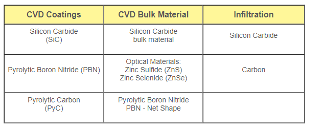
3.11.1 Chemical Vapor Deposition (CVD)
TevTech serves the advanced materials sector with custom-tailored chemical vapour deposition and infiltration solutions. Our team has a unique blend of design and operation knowledge with a wide range of materials. This knowledge gives our employees a better grasp of the problems and helps them to come up with efficient solutions, resulting in increased capacity, increased growth capability, and often lower operating expenses. We can assist your production team in developing a solution if they are wanting to boost production output or lower current operating costs.
TevTech's turnkey chemical vapour deposition systems go above and beyond our customers' expectations because to innovative design, high-quality components, and precision manufacture. Our engineering team is well-versed in how these systems work. As a result, we can offer ground-breaking designs that perform effectively in the manufacturing environment. Our vapour delivery systems and engineered hot zones are meant to be simple to set up and maintain for your manufacturing team. TevTech's design solutions are well known for their superior control and longevity.
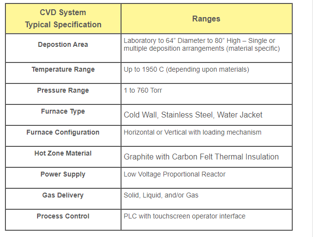
TevTech has designed and produced CVD systems with a variety of physical properties and operating parameter ranges.
3.11.2 Chemical Vapor Infiltration (CVI) description
Chemical Vapor Infiltration is a method of fabricating Ceramic Matrix Composites in which reactant gases permeate into an isothermal porous preform comprised of long continuous fibres and deposit. The deposited substance is the consequence of a chemical reaction on the surface of the fibres.
Diffusion or exerted external pressure drive the infiltration of the gaseous precursor into the reinforcing ceramic continuous fibre structure (preform).
The deposition fills in the gaps between the fibres, resulting in a composite material with a matrix of deposited material and a scattered phase of preform fibres.
Chemical Vapor Infiltration (CVI) is analogous to Chemical Vapor Deposition (CVD), in which the reactant gases react on the outside substrate surface to generate a deposition.
For the manufacture of silicon carbide matrix composites reinforced by silicon carbide long (continuous) fibres, chemical vapour infiltration is commonly used.
The vapour reagent is usually delivered to the preform in the form of a carrier gas stream (H2, Ar, He). A mixture of methyltrichlorosilane (MTS) as the precursor and hydrogen as the carrier gas forms a silicon carbide (SiC) matrix. According to the reaction, methyltrichlorosilane decomposes as follows:
CH3Cl3Si→SiC+3HCl
Diffusion removes the gaseous hydrogen chloride (HCl) from the preform.
A methane precursor is used to create a carbon matrix (CH4).
As long as the diffusing vapour reaches the reaction surface, the ceramic deposition continues to expand.
As the material is filled with solid ceramic, the porosity of the material decreases. However, due to the filling of the vapour routes with the forming ceramic matrix during the CVI process, access to the preform's inner areas becomes more difficult.
The transit of precursors is slowing down. The developing solid phase isolates the material's gaps from the vapour precursor's percolating network. Such inaccessible pores do not shrink any more, resulting in the composite's residual porosity.
When the preform surface pores are closed, the matrix densification ends. Ceramic composites manufactured using the CVI process may have a final residual porosity of 10-15%.
3.11.3 Chemical Vapor Infiltration (CVI) process
- The fibre preform is fabricated.
- The use of a debonding interphase is required. Chemical Vapor Infiltration (CVI) is used to deposit a thin layer of pyrolytic carbon (C) or hexagonal boron nitride (BN) on the fibre surface.
- Infiltration of a preceramic gaseous precursor into the preform. The preform is heated before being placed in a reactor containing a gaseous precursor. The gas infiltrates the preform, decomposing and depositing a ceramic deposit (matrix) on the fibre surface. The method is repeated until the preform surface's open porosity is closed.
- Abrading/machining the preform surface to open the percolating network's routes, allowing the matrix to be densified more.
- Re-infiltration-abrading cycles are repeated until maximal densification is reached.
- Surface coating for protection. To prevent ambient gases from penetrating into the composite during service, the open porosity is sealed. Over the sealcoat, an additional layer to protect the composite surface from oxidation can be added. Chemical Vapor Infiltration is used to deposit the coatings (CVI).
3.12.1 Liquid phase sintering
LPS (liquid phase sintering) is a method of fabricating high-performance, multi-phase components from powders. It entails sintering in a situation where solid grains and a wetting liquid coexist. LPS is used to treat a wide range of engineering materials in a variety of ways. Automobile engine connection rods and high-speed metal cutting inserts are two examples of applications for this technology. In the 1950s, scientists began to gain a better knowledge of LPS. The derived quantitative process models are being used in computer simulations to forecast the size, microstructure, and characteristics of sintered components. However, there are still several areas that require further investigation. This LPS review, which is based on over 2,500 publications, describes what happens when mixed powders are heated to the LPS temperature, with a focus on densification and microstructure evolution.
3.12.2 Introduction
Sintering is the process of combining packed particles that have been heated to near-melting temperatures. Sintering is shown by bonding between interacting particles as diffusion accelerates at higher temperatures. Sintering takes place at a variety of temperatures, but it speeds up as the particles get closer to their melting point. Because diffusion distances are shorter and curvature strains are greater as particle size decreases, it happens faster. When it comes to solid-state sintering, it's best to think about it in terms of melting temperature. At temperatures near 15 °C, snow sinters to produce ice, whereas alumina requires temperatures in excess of 1000 °C.
The formation of a liquid during the sintering cycle is a widely used option. LPS is a technique for sintering metals and composites that melt at different temperatures. The solid grains are usually soluble in the liquid in most cases. Because of the solubility, the liquid wets the solid, causing a capillary force to bring the grains together. Simultaneously, the high temperature softens the material, aiding densification even further. Liquids have high diffusion rates, resulting in faster sintering and lower sintering temperatures. LPS is the most used commercial sintering process since the final result is a composite with tailored qualities.
LPS was first used to fire ceramics with a glass bond. Glass becomes a viscous liquid at high temperatures; early porcelain was a popular example. Although the liquid phase in some ceramic compositions is a viscous glass, we refer to it as a liquid in this treatment.
In the 1930s, numerous materials were developed that revolutionised LPS: cemented carbides (WC–Co), porous bronze (Cu–Sn), tungsten heavy alloys (W–Ni–Cu), copper steels (Fe–Cu–C), and cermets (TiC-Fe). Oil well drilling tips, porcelain jacketed dental crowns, automotive valve seats, wire drawing dies, high-temperature bearings, electrical contacts, electronic capacitors, radiation shields, diesel engine turbochargers, electronic insulator substrates, golf club balance weights, ultrasonic transducers, and electronic sol
Price et al. Pioneered the mechanistic conception of LPS. Over the next 20 years, qualitative models arose based on data from a range of systems. Kingery presented a quantitative treatment, whereas Cannon and Lenel gave a qualitative interpretation. A decade later, Eremenko et al. Produced a brief book on the subject, which was followed by a more comprehensive account in 1985. As new applications appeared, the rate of publication increased, and articles on LPS and liquid phase sintered products now include over 100,000 contributors.
These efforts result in a conceptual understanding of the events that are taking place, as shown in Fig. 1 for two mixed powders. During heating, the solid grains undergo solid-state sintering. Different microstructure evolution processes are conceivable depending on the solid–liquid solubility relations. When a liquid wets a solid, this is a common occurrence. The freshly generated liquid enters between the solid grains, dissolves sinter bonds, and causes grain rearrangement in this scenario. Furthermore, the liquid boosts particle coarsening and densification transport rates due to solid solubility in the liquid. Pores are annihilated as a result of the surface energy associated with them, while the microstructure coarsens and bonds to increase stiffness.
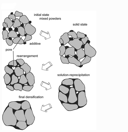
Starting with mixed powders and pores between the particles, a schematic of the microstructure changes during LPS is shown. The particles sinter during heating, but as a melt forms and spreads, the solid grains rearrange. Coarsening occurs as a result of the subsequent densification. Pore annihilation occurs in many products as diffusion in the liquid promotes grain shape changes, making pore elimination easier.
The LPS events are perfect for densifying hard materials that are difficult to manufacture with other methods. The WC–Co system is a good example, because the eutectic at 1310 °C allows micrometer-sized WC grains to be bonded into a dense component like a drill or cutting implement.
LPS can also be made with alloy powders that partially melt to form a semisolid structure instead of mixed powders. Tool steels are sintered using this method. A transient liquid forms and dissolves into the solid over time in another version. Porous bronze bearings are made using a mixture of copper and tin powders. Finally, in systems where the solid and liquid are insoluble, such as W–Cu, the rate of densification is determined by solid-skeleton sintering. Persistent LPS, on the other hand, is a type of LPS in which the solid is soluble in the liquid at the sintering temperature. The liquid solidifies as it cools, forming a composite microstructure with certain qualities.
3.13.1 IN-SITU PROCESSING
In-situ composites processing materials can be in any of the three states of matter, or a mix of them. The well-known Lanxide and XD materials were manufactured in a two-phase (solid/liquid) environment, and their outstanding features are well known. Despite the fact that Al-Si alloy was employed in the first Lanxide materials, researchers' attention is drawn away from the alloy as materials are developed using the Lanxide or XD methods.
The reactive nickel and titanium alloys and intermetallics, as well as ceramic-oxide systems, are the focus of in-situ processing. In contrast, in-situ production of SiC and TiC has been described via reactive infiltration of molten alloys Al-Si and Al-Ti into a carbon or graphite preform, with only microstructural investigations employing x-ray and microscopic techniques being described.
3.13.2 lanxide process
The Lanxide process, also known as pressure less metal infiltration, is a partial reaction method for producing metal-matrix composite materials. It involves selecting an initial alloy (usually aluminium with about 3% magnesium and 10% silicon) and then maintaining conditions in which the polycrystalline reaction product has a mechanical compliancy.
In protocols where the final casting contains a cavity in the shape of the casting pattern, the metal is poured into the cavity, which has been designed to lie in the midst of a quantity of "filler" appropriate to the reaction product, and wicks itself to fill the pores in the filler.
The procedure is typically used to make alumina-reinforced aluminium, but it can also be used to develop ceramic layers inside metal encasements to provide pre-stressing.
The Lotus Elise sports car's original brake discs were made of Lanxide metal-matrix composite materials, however they proved to be uneconomic.
3.14.1 Processing, properties alumina matrix composites
There are two main groups in which the processing routes for fabricating AMC’s can be classified:
1. Liquid State Processes
2. Solid State Processes
1) LIQUID STATE PROCESSING
There are four processing routes which come under the category of liquid state processing: Stir casting, spray deposition, infiltration process, in-situ reaction synthesis.
Stir Casting
In 1968, S. Ray pioneered stir casting. The reinforcements are fed into the molten magnesium with the help of steady stirring action, and the mixture is allowed to harden after that. The vortex technique is the most often utilised way for achieving consistent stirring activity. In this process, a rotating impeller creates a vortex of molten magnesium, and pre-heated ceramic particles are allowed to mix into the metal. Due to the dispersion of reinforcing particles and their settling during the solidification process, it is difficult to obtain uniform reinforcement distribution in the metal matrix. As a result, the final dispersion of particles within the matrix is determined by the wetting of molten aluminium with particulate reinforcement, solidification rate, and relative density.
Spray Deposition
The thermal spray process and the osprey process are two types of spray deposition methods. The former is a process in which molten metal is continually fed into the heat injection zone, whereas the latter is a procedure in which cold metal is continually fed into the heat injection zone. The spray procedure has been widely utilised to make AMCs by infusing reinforcements into the spray, which can take the shape of whiskers, particles, or fibres. Although it is difficult to achieve homogeneous reinforcement distribution in the metal matrix using this approach, spray deposition composites are quite inexpensive.
Infiltration Process
The infiltration procedure is one of the most cost-effective ways to fabricate AMCs. In this process, aluminium in molten form is injected into the spaces between the porous structure of the reinforcements which may be continuous or short fibres, whiskers or particulates. Reinforcements are allowed to mix with liquid carrier and a binder to prepare slurry which is further infiltrated as in paper making process. After this, the preform is heat treated to improve the binder's binding capabilities. Because of the unequal distribution of reinforcements into the metal matrix, the composites generated by the infiltration method are porous to some extent and have local vibrations.
In-Situ Reaction Synthesis
In-situ reaction synthesis is a relatively new manufacturing method that involves the incorporation of reinforcements into a metal matrix by chemical reactions between elements and compounds. In-situ or reactive processing methods include liquid-liquid, solid-liquid, liquid-gas, and other salt processes. One of the most common examples of this technique is the DIMOX procedure. This is a procedure in which a ceramic preform is placed in a crucible and an Al-Mg alloy is deposited on the crucible's upper section. The assembly is allowed to heat to the desired temperature in the presence of a nitrogen-rich gas combination. There are some thermodynamic constraints on the nature and composition of the reinforcements, but this approach can produce a consistent reinforcement arrangement and a clean interface between them.
2) SOLID STATE PROCESSING
The two procedures that fall within the heading of solid state processing methods are powder metallurgy and diffusion bonding.
Powder Metallurgy
Powder metallurgy is a high-temperature process in which metal alloys and reinforcements are uniformly mixed, degassed, and sintered. It is one of the most adaptable methods for creating AMCs. In this procedure, the primary material is first powdered into small particles, and then the powdered ceramics and metals are allowed to mix in the needed proportions based on the composite qualities. The mixture was then poured into a mould, where the creation of ceramics into metal matrix was finished under high temperature and pressure.
Diffusion Bonding
Diffusion bonding is a solid state processing technique used to make mono filament reinforcement AMCs. The inter-diffusion of atoms across the surfaces of particles and metal causes bonding. The described bonding procedure is used to make 6061 Al-boron fibre composites. Although this procedure can handle a wide range of metal matrices, it is challenging to establish a consistent distribution of fibres throughout the metal matrix. Furthermore, diffusion bonding is challenging to achieve complicated components and forms.
3.14.2 APPLICATIONS OF AMCs
The use of various types of reinforcements in an aluminium matrix using both solid and liquid state processes has resulted in a wide range of applications for aluminium matrix composites. Mechanical assemblies, automotive, and aerospace sectors have all used particle reinforced aluminium matrix composites [26]. These materials are also employed in automotive and railway braking systems. PAMCs also makes baseball shafts, skate shoes, bicycle frames, and carrier plates, among other things. Military tanks employ SiC reinforced AMCs as track shoes. They're also employed in cylinder-piston arrangements [3]. CFAMCs are used in the electrical industry because of their strong electrical and thermal conductivity as well as their great dimensional accuracy. These composites are also employed in the manufacture of automatic push rods, brake callipers, and retainer ring motors [27]. These thin-walled rings allow the motors to run at such a high speed. As a result, AMCs have a wide range of applications in the manufacturing sector due to their light weight and accurate physical and chemical properties.
3.14.3 Processing, properties and applications of SiC whisker reinforced
SiC whisker-reinforced ceramic composites were created as a class of ceramic materials for possible structural applications due to the significant increases in mechanical properties these materials offered over monolithic materials. Strength, fracture toughness, thermal conductivity, thermal shock resistance, and high temperature creep resistance were all improved by incorporating SiC whiskers into alumina ceramics. These discovery sparked a multi-year investigation into this class of composites.
The first SiC whiskers were created in the early 1960s. However, they were originally intended to be used to reinforce metal matrices such as aluminium. Because of the expensive cost of the whiskers, these metal matrix composites were only a minor commercial success. It wasn't until the 1980s when whisker reinforcement was first used in ceramics, specifically alumina. SiC whiskers shall be defined as acicular or needle-like shaped, discontinuous, virtually single crystals with diameters ranging from 0.1 to 5 m and lengths greater than 5 m for the purposes of this article.
This sets them apart from other fibre materials, which are polycrystalline, amorphous, or have many coverings. It also restricts the dimensional range to relatively small levels, though not to the nanoscale level. Prior to the mid-1970s, much of the early research and published data used the vapor-liquid-solid (VLS) method to generate modest quantities of SiC whiskers. However, there were few markets for these minerals at the time, and the costs were excessively high due to the little quantities produced.
Since then, methods for mass-producing whiskers at a reasonable cost have been devised. These mass-production methods, which were mostly mentioned in patent literature, utilise carbothermic reduction reactions of low-cost silica and carbon precursors such rice husks to manufacture industrial-scale quantities of whiskers at competitive prices. SiC whiskers have thus become economically feasible reinforcing agents in large-scale, high-volume component applications.
The need for whiskers has increased as a result of the development of composite materials and the commercial success of certain of these products. Over the years, a number of companies have experimented with various whisker growth procedures, and multiple patents have been issued in the field. Commercial whisker sales are now confined to a few companies throughout the world, with SiC whiskers being the most common. Furthermore, TiC, TiN, Al2O3, mullite, Si3N4, and B4C whiskers have been generated and examined. SiC, on the other hand, continues to attract the most attention and commercial success. 2.
3.14.4 Toughening Behavior of Whisker-Reinforced Composites
Fracture-whisker interaction resulting in crack bridging, whisker pullout, and crack deflection are the key toughening mechanisms in SiC whisker reinforced alumina composites, according to an analysis of the toughening behaviour. Debonding at the alumina matrix-whisker interface (typically associated with crack deflection) must occur during crack propagation for these mechanisms to work, allowing the whiskers to span the fracture's wake. As demonstrated in Figures 1 and 2, the fracture surfaces of whisker-reinforced composites are microscopically rough, with whiskers easily visible.
According to micromechanical modelling and existing experimental evidence, composite toughness, KIC (composite), is the sum of matrix toughness, KIC (matrix), and a contribution owing to whisker toughening, KIC (whisker) (whisker reinforcement). KIC (composite) = KIC (matrix) + KIC (whisker reinforcement), in other words (1) A relationship was shown in one study for the increase in fracture toughness caused by whisker reinforcing.
3.15.1 Zirconia Toughened Alumina (ZTA)
ZTA Ceramics Description
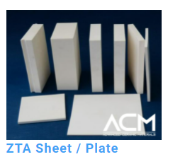
ZTA (zirconia toughened alumina) is a high-strength, wear-resistant substance that can be utilised as a bridge between zirconia particles and alumina. ZTA ceramic material has been proven to be stronger and tougher than ordinary alumina ceramics.
In most cases, ZTA includes 10-20 percent ZrO2 in alumina. The qualities of the ceramic can be customised to fit the application depending on the proportion of content. Because pure zirconia is so expensive, ZTA with good toughness is an excellent alternative.
3.15.2 ZTA Ceramics Properties
Chemical Formula | Zr-Al2O3 |
Density | 4.1-4.38 g/cm^3 |
Hardness | 1750-2100 Knoop |
Elasticity | 45-49 x 10^6 psi |
Flexure Strength | 100-145 ksi |
Poisson's Ratio | 0.26 |
Fracture Toughness | 5-7 MPa m^1/2 |
Coefficient of Thermal Expansion | 8.0-8.1 x 10^-6 1/C |
Thermal Conductivity | 20.0-21.0 W/mK |
Shock Resistance | 325 °C |
Maximum Working Temperature | 1650 °C |
3.15.3 ZTA Ceramics Applications
ZTA ceramics might be a first choice when high strength and erosion resistance are required. ZTA is well suited for industrial components such as valve seals, sleeves, pump pistons, and spraying nozzles.
In addition, ZTA is in high demand in the manufacturing industry. Its applicability is superior to that of other cutting tool materials due to qualities such as high hardness, high wear resistance, chemical inertness at room temperature, high hot hardness, rupture strength, moderate heat resistance, and compressive strength.
3.15.4 Other Applications:
-Standoffs
-Insulators
-Probe Bodies
-Bushings
-Fluid Delivery System Components
-Pump Position Sleeves
-Instrument
-Sensor Bulbs
-Impellers
-Analytical instrument Columns

3.16.1 Ceramic matrix composites (CMCs)
A subgroup of composite materials and a subgroup of ceramics, respectively. They are made up of ceramic fibres that are encased in a ceramic matrix. Both the fibres and the matrix can be made of any ceramic material, including carbon and carbon fibres, which can be considered a ceramic material.
CMCs were developed to address issues with traditional technical ceramics such as alumina, silicon carbide, aluminium nitride, silicon nitride, or zirconia, which fracture easily under mechanical or thermo-mechanical stress due to cracks caused by microscopic imperfections or scratches. As with glass, the crack resistance is very poor. Particles (so-called monocrystalline whiskers or platelets) were implanted into the matrix to boost crack resistance or fracture toughness. However, the improvements were minor, and the goods were only used in a few ceramic cutting tools. Only the incorporation of long multi-strand fibres has significantly improved crack resistance, elongation, and thermal shock resistance, resulting in a variety of novel applications. Ceramic matrix composites (CMC) utilises reinforcements to improve the combined material system's fracture toughness while still utilising the ceramic matrix's inherent high strength and Young's modulus. A continuous-length ceramic fibre with an elastic modulus that is typically lower than the matrix is the most prevalent reinforcing embodiment. The functional role of this fibre is to (1) increase the CMC stress for the progression of micro-cracks through the matrix, thereby increasing the energy expended during crack propagation; and (2) to increase the CMC stress for the progression of micro-cracks through the matrix, thereby increasing the energy expended during crack propagation.
(2) when thru-thickness cracks appear across the CMC at greater stress (proportional limit stress, PLS), to bridge these cracks without fracturing, resulting in a high ultimate tensile strength for the CMC (UTS). Ceramic fibre reinforcements boost the composite structure's initial resistance to crack propagation while also allowing the CMC to escape the abrupt brittle failure that monolithic ceramics are prone to. Ceramic fibres in polymer matrix composites (PMC) and metal matrix composites (MMC) often shatter before the matrix due to the higher failure strain capabilities of these matrices.
The most common fibres used in CMCs are carbon (C), special silicon carbide (SiC), alumina (Al2O3), and mullite (Al2O3SiO2). C, SiC, alumina, and mullite are typically used as matrix materials. Abnormal grain growth in certain ceramic materials, such as SiC and silicon nitride, can result in a microstructure with elongated big grains in a matrix of tiny rounder grains. Toughening occurs in AGG-derived microstructures as a result of crack bridging and crack deflection by the elongated grains, which can be thought of as in-situ created fibre reinforcement. Ultra-high-temperature ceramics (UHTCs) have recently been researched as a ceramic matrix in a new CMC class known as Ultra-high Temperature Ceramic Matrix Composites (UHTCMC) or Ultra-high Temperature Ceramic Composites (UHTCC).
CMC names are usually a combination of fibre type and matrix type. Carbon-fiber-reinforced carbon (carbon/carbon), for example, or carbon-fiber-reinforced silicon carbide (C/SiC). The manufacturing process is sometimes included, thus a C/SiC composite made with the liquid polymer infiltration (LPI) process (see below) is referred to as LPI-C/SiC.
C/C, C/SiC, SiC/SiC, and Al2O3/Al2O3 are the most common commercially available CMCs. They differ from traditional ceramics in the following characteristics, which are detailed below:
- Elongation to rupture up to 1%
- Strongly increased fracture toughness
- Extreme thermal shock resistance
- Improved dynamical load capability
- Anisotropic properties following the orientation of fibers
3.17.1 carbon/carbon composites
Carbon–carbon composites can be made using a variety of processes, including all-solid pyrolysis with thermosetting resins, pitch method with liquid infiltration carbonization, or CVD approach. Fabrication of a 3D (three directionally reinforced) or MD porous carbon fibre preforms with the desired shape or a porous carbon–carbon skeleton (UD, 2D or 3D) using carbon fibres and a carbonaceous matrix is followed by densification of C/C composites (see figure 3). Densification can be performed through vapour phase infiltration (CVI), in which hydrocarbon gases such as methane, propane, and other hydrocarbon gases permeate a porous fibre structure heated to 1000–1400C and crack therein. In a large-scale furnace, an isothermally heated stack of components is impregnated concurrently. The gases should primarily penetrate the pores and interfilamentary gaps before cracking. However, these gases have a tendency to break at the outer surface, obstructing passages and resulting in blocked pores. The surfaces are ground and the components are reinfiltrated to create thick composites. CVD is a time-consuming method that can take months to produce dense carbon–carbon composites. Porous structures can also be impregnated with liquid phase pitch/phenolic resin, then carbonised and heat treated at high temperatures (1000–2700°C). The pitch/resin matrix can be pyrolyzed at room temperature or under high pressure (HIP).
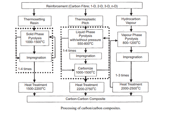
Depending on the densification method, two or more densification cycles are required to achieve the appropriate density, with HIP methods requiring fewer impregnation cycles. A new method of intermediate graphitisation has been developed, in which the composites are heat-treated to high temperatures following particular impregnation/normal pressure carbonisation cycles and then reimpregnated. The pores are opened up for further infiltration with this intermediate high temperature heat treatment. Figure 4 depicts a broad comparison of densification methods. A mix of processing routes is frequently utilised. Fabrication of host composites by the pitch or resin method, followed by densification and pore sealing using CVD.
3.17.2 Porous carbon -carbon composites
By combining carbon black, petroleum pitch, and a solvent, then granulating the mixture and carbonising the resulting pellets in an inert atmosphere, granular porous carbon/carbon composites were created. Mercury porosimetry and scanning electron microscopy are used to investigate the pore structure of this material. A model for it is proposed based on the acquired results. The impact of carbon black type, filler/binder ratio, heat treatment temperature, and mixing time on surface area, total pore volume, and strength of final pellets was studied. Due to its meso- and macroporous structure and low ash content, the examined material can find commercial applications as a catalyst support and as an adsorbent for adsorption of big molecules when compared to activated carbons.
Porous carbon fiber-carbon binder composites are a relatively unknown family of materials that play an important role in RTG space power systems and have a lot of potential in light absorption and gas adsorption applications. These uses are made possible by the porous carbon fiber-carbon binder composites' unique combination of physical characteristics. The material's open, yet robust, form is perhaps the most important of its physical characteristics, since it adds greatly to its use in the fields of application outlined above. In addition, the ability to adjust various physical qualities increases the carbon composite material's potential use. The material's pore structure, which is critical in fluid separation and gas storage applications, may be adjusted by carefully selecting the precursor carbon fibre as well as the manufacturing and activation approach. New applications for porous, adsorbent carbon fiber-based monoliths are likely to emerge in the near future. These applications will be less cost-sensitive than many existing applications of commodity GAC, but they will be applications for which porous carbon fiber-carbon binder composites are ideally suited due to their new characteristics. ORNL's current research focuses on increasing the material's homogeneity and critical features, as well as containing or lowering the cost of our porous carbon fiber-carbon binder composites.
Key takeaways:
• Furnace fixturing, heat shields, load plates, heating components, and X-ray targets are all commercial applications of carbon/carbon composite materials. Rocket nozzles must be able to endure a rapid temperature rise in a highly corrosive environment while maintaining a high level of integrity.
• Carbon-Carbon can be customised to produce a wide range of products by varying the fibre type, fibre presentation, and matrix.
• Carbon-Carbon is generally employed in applications involving extremely high temperatures and friction. The desirable qualities of the two constituent carbon materials are combined in Carbon-Carbon.
References:
1. Composite Materials: Engineering and Science, by Matthews and Rawlings, CRC Press.
2. An Introduction to composite material, by D.Hull and T.W. Clyne, Cambridge University press.
3. Metal Matrix Composites, Thermomechanical Behaviour by M.Taya, and R.J.Arsenault, Pergamon Press, Oxford.
4. Fundamentals of Metal Matrix Composites by S.Suresh, A.Martensen, and A.Needleman, Butterworth, Heinemann
5. Mechanics of composite materials, R. M. Jones, Mc Graw Hill Book Co.