Unit – 4
Polymer matrix composites
Polymer matrix composites are materials that contain a matrix polymer as well as inclusions inside that matrix polymer.
As matrix polymers, both thermoset and thermoplastic polymers can be employed. The matrix polymer is also referred to as a binder since it holds the inclusions together (and therefore “binds”).
Continuous fibres (such as glass, carbon, aramid, basalt, or polymer fibres), short fibres (such as chopped glass fibres or chopped carbon fibres), platy inclusions (such as exfoliated clay platelets), spherical particles (such as glass microspheres), particles with irregular shapes (such as carbon black particles or fumed silica particles, which are aggregates of very small particles), and spherical particles (such as glass microspheres) are some of the Because it "fills" the polymer matrix, the word "filler" is frequently used to describe an inclusion.
Composites have qualities and performance qualities that the matrix polymer alone cannot match, such as increased stiffness, strength, impact resistance, heat resistance, abrasion and wear resistance, and gas barrier. Depending on the needs of the application, a composite can be constructed to exhibit such benefits isotropically or anisotropically.
Individual layers (plies), which each contain unidirectionally oriented continuous fibres in a polymer matrix, are stacked at different angles to form laminates that are isotropic in-plane but weak in the orthogonal (through-thickness) direction in the vast majority of continuous fiber-reinforced composites used today. A 3-dimensional woven fabric is frequently utilized as the reinforcement instead of stacking layers of plies containing unidirectionally oriented fibres when excellent qualities in the through-thickness direction are required.
Nanocomposites are composites in which nanofillers (such as carbon nanotubes, exfoliated clay platelets, or carbon black nanoparticles) have been disseminated in a polymer. Nanofillers and nanocomposites are not defined by a single universally accepted criterion. A nanofiller is defined as an inclusion with a length of less than 0.5 microns (500 nanometers) in at least one primary axis direction, while a polymer matrix nanocomposite is defined as a composite that contains a nanofiller spread throughout a polymer matrix.
Any one or a combination of (often dramatically) increased stiffness (modulus), strength, dimensional stability, thermal stability, electrical conductivity, flame retardancy, chemical resistance, and/or optical clarity; decreased gas, water, and oil permeability; and more attractive surface appearance are among the benefits sought in designing nanocomposites.
Our polymer and composites expertise at Bicerano & Associates assists our clients in developing polymers and composites for any purpose.
Key takeaways:
• Polymer matrix composites are utilized in MRI scanners, C scanners, X-ray couches, mammography plates, tables, surgical target instruments, wheelchairs, and prosthetics, among other medical devices.
• Polymer-matrix composites are the most widely used advanced composite materials, owing to their ease of production compared to carbon-matrix, ceramic-matrix, and metal-matrix composites, as well as the comparatively excellent bonding between polymers and fillers and the low porosity of unfoamed polymers (low compared to cement).
4.2.1 Thermosetting plastic
Thermoplastics and thermosets are the two main types of thermoplastics. At normal temperatures, thermoplastics provide strong, long-lasting adhesion, and they can be softened for application without degrading. Nitrocellulose, polyvinyl acetate, vinyl acetate-ethylene copolymer, polyethylene, polypropylene, polyamides, polyesters, acrylics, and cyanoacrylics are some of the thermoplastic resins used in adhesives.
4.2.2 Thermoplastic
Like thermoplastic elastomers like styrene-isoprene-styrene block copolymers, it can be used as an adhesive. Polymers provide strength, flexibility, and the capacity to spread and interact on an adherend surface—all of which are necessary for appropriate adhesion levels to form.
At normal temperatures, thermoplastics provide strong, long-lasting adhesion, and they can be softened for application without degrading. Nitrocellulose, polyvinyl acetate, vinyl acetate-ethylene copolymer, polyethylene, polypropylene, polyamides, polyesters, acrylics, and cyanoacrylics are some of the thermoplastic resins used in adhesives.
4.2.3 Rubber
Composites made up of nanofillers like OC, CNT, graphene, and nano graphite, as well as nanostructured fillers like CB and silica, show significant improvements in properties when compared to composites made up of only one type of filler, such as mechanical reinforcement and electrical and thermal conductivity.
For example, nano- and nanostructured fillers have synergistic effects when it comes to improving mechanical qualities.
When relevant filler features are identified, the behaviour of nano- and nanostructured fillers may be rationalized. For example, to improve the composite initial modulus as a function of the filler–polymer interfacial area, a common master curve can be created.
4.3.1 Hand Lay-Up
Hand lay-up moulding is the process of laying down reinforcement textiles and layering on the matrix resin until the appropriate thickness is achieved. This is the most time-consuming and labor-intensive composite processing technology, yet it is used in conjunction with the autoclave method to produce the majority of aerospace composite products. Long fibres can be aligned with controlled orientational quality thanks to the hand assembly involved in the lay-up technique. This approach also has the advantage of being able to accommodate irregularly shaped goods. Low-performance composites, such as fiber-glass boats and bath tubs, take advantage of these advantages. The earliest and most basic method for making reinforced plastic laminates is hand lay-up. The hand lay-up processes require a small amount of capital. A spray gun for applying resin and gel coat is usually the most expensive piece of equipment. Some fabricators pour or brush the resin into the moulds, eliminating the need for a spray gun. The size of the part that can be created is almost limitless. Wood, sheet metal, plaster, and FRP composites can all be used to make moulds.
• Typically used to manufacture polyester or epoxy resin parts such as boat hulls, tanks and vessels, and pick-up truck canopies • The procedure is relatively straightforward; the resin and reinforcement are applied against the surface of an object.
• open (one-sided) mould and leave to cure, or spray-up the resin/reinforcement onto the mould with a spray gun.
• To improve surface quality and protect the composite from the outdoors, a gel coat is frequently put to the mould before to use.
• A gel coat is a thin layer of resin that is typically seen on the exterior surface of smaller boats. It is usually 0.4 to 0.7 mm thick.
4.3.2 Spray-up Molding
• Using a spray gun and a fibre cutter, spray-up moulding is substantially less labour demanding than manual lay-up moulding. Only short fibre reinforced composites, however, can be manufactured. • A continuous fibre is fed into the cutter and chopped, then sprayed onto a mould with a stream of resin mist and catalyst given via separate nozzles.
• The sprayed fibre and resin combination cures quickly at room temperature on the mould, and the product is created.
• Large and complex-shaped things can be easily manufactured thanks to the spraying process.
4.4.1 Matched-die Mould Methods
The matched-die moulding approach encompasses a variety of moulding techniques. All of these approaches have one thing in common: the mould is made up of two sections with a cavity between them. The cavity's shape matches the shape of the object to be moulded. Molds are typically made of cast iron, steel, or an aluminium alloy. In some cold moulding procedures, fibre reinforced polymers or wooden moulds are also employed. The moulds' mating surfaces are polished, cleaned, and then coated with a releasing agent. The gel coat is next applied. The gel coat is a unique resin that adheres to the surface of the moulded item while it cures, giving it a smooth finish. Colorants and other additives are added to the gel coat resin to improve its resistance to wear, corrosion, heat, flame, weathering, and other factors. When the moulded part is to be adhesively connected to another part, the gel coat is not given because it may prevent proper bonding. In the moulding materials, both thermosetting and thermoplastic resins are used. Thermoplastics in general, and some thermosets in particular, require a greater process temperature than ambient. This is accomplished by heating the mould or the moulding. Excess resin and volatile materials are vented through venting apertures in the moulds.
The most frequent matched-die moulding process is compression moulding. It's used to make car body panels, electrical appliance and machine housings, covers, sinks, and a variety of other things. Figure 3.1 depicts typical moulds, which might have a single cavity or many cavities with complex curved geometries. It's possible that there's a way to heat one or both of the moulds. The pressure is applied by placing the moulds in a mechanical or hydraulic press, or by using some other method. Pressure and temperature can be precisely applied, as well as their duration and cycles. The procedure is extremely simple to automate. When pressure and temperature are applied, the mould material softens, flows, and fills the mould cavity. Furthermore, keeping the heat and pressure on speeds up the curing process. Compression moulding can provide dimensions that are close to those of the desired finished product. Trimming and machining are reduced to a large amount as a result of this. A predefined quantity of BMC, SMC, resin coated preforms/fabrics, or prepregs can be used as the moulding material. It is placed in the mould, which is then sealed. The resin cannot flow out due to a barrier at the edge. The thickness of the portion is also controlled by the depth of the barrier. During the curing process, heat and pressure are used. The mould is opened and the portion is removed once the curing is complete.
Some resins, such as polyesters and epoxies, are very exothermic and do not require additional heat to cure. With these resins, the moulding material can be cold pressed. When a product is smaller in size and has a simpler shape, cold press moulding is a cost-effective option (flat or slightly curved panels).
Cold stamping, like compression moulding, is most commonly employed with thermoplastic sheets. The thermoplastic sheets are heated before being placed in the mould with reinforcements and cold pressed. Figure 3.2 shows an expansion of this approach to continuous manufacture of fibre reinforced thermoplastic laminates. Hot rollers melt the resin and urge it to penetrate and coat the individual fibres while alternate layers of fibre fabrics and thermoplastic films are run through them. After that, the consolidated laminate is run through cold rollers to cure and harden it.
Conforming is also a matched-die moulding method designed to give a composite item a better surface polish and durability. First, a thin thermoplastic layer is thermoformed and placed on the mould (Fig. 3.3). After that, the moulding composite material (BMC, SMC, or resin-coated cloth) is hot pressed on top of the thermoformed thermoplastic layer. The thermoplastic layer adheres to the moulded item, resulting in a smooth surface with good characteristics. To achieve desired surface qualities, various additives can be premixed in the thermoplastic layer.
Press moulding is similar to compression moulding in that it is used to create flat, slightly curved, and corrugated laminates. A perforated release film (e.g., Teflon film with perforations every 50 mm) and a bleeder (e.g., glass cloth, jute cloth, or absorbent paper) are applied on both sides of the composite part to produce good quality laminates with uniform resin content (Fig. 3.4). A peel ply (e.g., nylon cloth) is also utilized in some applications to produce the desired surface finish. Excess resin is squeezed out by applying pressure, and it travels through the pores of nylon cloth and the perforations of Teflon film before being absorbed by the bleeder. The pressure is applied normally during the gelation process to prevent excessive resin loss and to ensure uniform resin distribution. Vacuum can be applied to one of the surfaces of the mould cavity (shown in Fig. 3.4, either the top or bottom surface) to achieve a homogeneous flow of surplus resin out of the moulding.
Injection moulding is a matched-die moulding technique that is particularly well suited to thermoplastic resin systems. Injection moulding is also possible with some thermosets. If the reinforcements are in the form of particles or extremely short fibres, they can be premixed with resin along with any additional additives. In an injection chamber, the mixture is first heated. The heated fluid mix is then injected under high pressure into the closed mould cavity and allowed to cure. After opening the mould, the cure section is removed. The process can be used to make small to medium-sized parts including valves, gears, and instrument panels.
If the reinforcements come in the shape of preforms or fibre fabrics, they are placed in the mould cavity before the fluid resin is injected. Resin injection moulding is the name of the procedure. The resin is able to penetrate the fibre lay-up thanks to the injection pressure. A vacuum is also provided to the mould cavity to help the resin penetrate and distribute evenly. Resin is injected at multiple points in bigger mouldings, such as boat hulls. Cold cure resins with a low viscosity and a long gel time are also preferable in these applications because the injection time is longer.
Measured amounts of two liquid precursors, such as a polyol and an isocyanate, are combined in a chamber and then injected into a hot mould cavity containing pre-laid reinforcements in reaction injection moulding. Prior to injection, chopped strands and particle reinforcements can be mixed with precursors. The procedure is most commonly utilized in polymethane-based systems and requires a modest injection pressure. It's ideal for mass-producing composite parts in large quantities.
4.4.2 Autoclave moulding
With a few exceptions, autoclave moulding is quite similar to vacuum bagging. The autoclave machine (Fig. 4.22(a)) provides the heat and pressure that the bio composites require during the curing step. This procedure entails firmly stacking prepregs in a mould in a specified order. To prevent the polymer from sticking to the mould surface, a release gel is placed to the mould surface. This method also allows for the usage of cores and inserts. Then, as previously indicated (Fig. 4.22(b)), vacuum bagging is used to remove any trapped air between the layers. After that, the entire assembly is placed in an autoclave machine, where heat and pressure are applied to ensure uniform and effective matrix dispersion as well as good fibre-matrix interfacial adhesion or bonding for a set period of time. Curing is the term for this step. After the assembly has cooled and the vacuum bag has been removed, the composite component is taken from the mould.
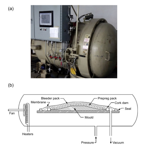
In the aerospace sector, autoclave moulding is commonly utilized to produce high-quality prepreg-based parts. A peel ply, bleeder ply, and vacuum bag are placed on top of the preimpregnated laminae on the tool surface. Once sealed, the complete assembly is placed in an autoclave (which is a combination of an oven and a pressure chamber) to cure. With the right ramps and dwells, the autoclave allows for great pressure and temperature control. The vacuum helps to consolidate the plys while also eliminating volatiles that may occur during the moulding process, which helps to prevent porosity. The vacuum and pressure operating on the assembly work together to deliver consistent pressure across the component surface, resulting in a very high-quality laminate with fibre volume fractions of 60–70% and excellent dimensional control. The technique produces some of the highest-quality laminates with the lowest void content, but it needs a significant upfront investment in the autoclave. The technique achieves extremely high levels of consistency, dimensional tolerance, and quality, making it ideal for the production of prefabricated jackets that will be adhesively attached on the battlefield. However, the expenditures of an autoclave and prepreg are likely to make this prohibitively expensive unless the amount of quality control and dimensional precision required is a need.
Key takeaways:
• Injection moulding can manufacture an astounding number of pieces per hour and is extremely efficient. The cycle time varies depending on the complexity and size of the mould, ranging from 15 to 120 seconds. Extrusion moulding, compression moulding, blow moulding, injection moulding, and rotational moulding are the five types.
RESIN TRANSFER MOULDING (RTM)
Resin Transfer Moulding (RTM) allows the moulding of components with complex shapes and large surface areas with a good surface finish on both sides. It's a process that works well for short and medium production runs, and it's used in a variety of transportation applications (truck cabs are an example).
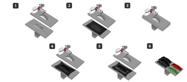
• The Mould is placed in the pressure machine, which is in charge of applying pressure to the resin container in order to force the resin into the moulding region.
• Basfiber Fabrics are positioned over the mould in the thicknesses and layers required to obtain the expected properties of the final product.
• In the mould, heat and pressure are applied to force the resin to cover all of the space between the fabric layers, ensuring resin impregnation.
• After acquiring the mould form, the finished product is cured and taken from the mould for the finishing stage.
• The product is polished and varnished for a brighter outcome, and the edges are cut.
• The product can be painted in a variety of colours, allowing things to be made on a production line.
When it comes to closed moulding for composite manufacture, there are a variety of solutions. Compression moulding produces low-cost parts for high-volume production, but it demands a large capital investment in presses, equipment, and tooling. Its applications to non-structural components are also limited because to the difficulties in controlling fibre orientation in the part. Vacuum infusion moulding, on the other hand, has a modest initial investment but provides cycle durations that are comparable to or slower than standard open moulding. Transfer of Resin Moulding fills the need, allowing for the production of mid-volume parts at a low cost of capital. Pultrusion and filament winding are two processes that provide continuous fibre reinforcement but are confined to particular component geometries. In the case of RTM, on the other hand, the fibre orientation can be easily adjusted, making the method suited for structural applications. RTM manufactures propeller blades for planes, for example.
Pressure is the driving factor in RTM. As a result, the pressure inside the mould cavity will be higher than the pressure outside. Vacuum infusion methods, on the other hand, use vacuum as the motive force, and the pressure inside the mould cavity is lower than air pressure.
A liquid thermoset resin system is poured into a closed mould cavity that has been preloaded with dry reinforcements in the RTM process. The moulded FRP product is released from the mould when the thermosetting resin has cured.
The level of sophistication of each of these systems is determined by the size of the manufacturing process, the part's dimensions, and the amount of capital available. Prototypes and one-off mouldings can be manufactured with gravity or vacuum impregnation into low-cost, low-strength moulds, whereas high-volume manufacture can require high-cost steel tooling and a sophisticated resin supply system.
4.6.1 Filament Winding
Filament winding produces hollow structures that are extremely strong. The filament winding process produces an optimized product that is ideal for pressure vessels, aerospace components, golf clubs, military armaments, and hundreds of other applications by cross-weaving continuous rovings of carbon fibre, fiberglass, or aramid fibre and embedding them in a resin matrix. This is the production procedure of choice anywhere strength at a low weight is required, as well as durability and certain performance qualities.
Three decades of filament winding.
With our precision filament winding method, Advanced Composites Inc. Has been producing high-grade composite tubing, aircraft structures, and other specialty products for almost two decades. With a variety of filament winding machines and the ability to create, prototype, and build at nearly any scale, ACI has established itself as a dependable production partner for any company that requires filament-wound structures. In addition to winding, we use compression moulding, reaction injection moulding, and lay-up methods in our manufacturing process.
Hollow, robust geometries are created through filament winding. Advanced Composites Inc. Creates carbon fibre tubing, fibreglass tubes, and other hollow structures using our filament winding methods. The tensile strength, circumferential strength, and strength-to-weight ratios of these tubes and structures are exceptional.
4.6.2 The process of filament winding, explained.
There are two main components to the filament winding process. A carriage arm travels horizontally up and down the length of the mandrel while a stationary steel mandrel rotates. A winding eye on the travelling arm collects and distributes the rovings, which are commonly made of carbon, fibreglass, or a combination of the two. The rovings wrap around the mandrel as it rotates, forming a composite layer on the mandrel's surface. The rate of motion of the carriage and the rotating speed of the mandrel, both of which are automated, define the precise alignment of the composite matrix. The fibres are impregnated in a resin before they come into contact with the mandrel, and the resin solidifies with the fibre to form the final composite material. For product optimization, resin kind, fibre type, wind thickness, and wind angle are all engineered.
4.6.3 Injection moulding
Injection moulding (also known as injection moulding in the United States) is a manufacturing method that involves injecting molten material into a mould. Injection moulding can be done with a variety of materials, including metals (for which die-casting is used), glassware, elastomers, confections, and, most typically, thermoplastic and thermosetting polymers. The part's material is supplied into a heated barrel, mixed (using a helical screw), and then injected into a mould cavity, where it cools and hardens to the cavity's configuration. [1]:240 Molds are manufactured by a mould-maker (or toolmaker) from metal, usually steel or aluminium, and precision-machined to produce the features of the required part after a product is created, usually by an industrial designer or an engineer. Injection moulding is commonly utilized to produce a wide range of parts, from small components to whole automotive body panels. Some basic injection moulds can be made using advances in 3D printing technology, which use photopolymers that do not melt during the injection moulding of some lower-temperature thermoplastics.
Injection moulding is done with a unique equipment that consists of three parts: an injection unit, a mould, and a clamp. To make the injection moulding process easier, parts must be properly developed; the material used for the part, the intended shape and features of the part, the material of the mould, and the properties of the moulding machine must all be considered. This diversity of design considerations and opportunities contributes to injection molding's adaptability.
Key takeaways:
• Filament winding has been used to make pressure vessels, pipes, and drive shafts, as well as other application methods such as hand layup, pultrusion, and braiding. Fiber tension is used to compact the material, and resin content is mostly measured.
•The cost of filament winding is less than that of prepreg for most composites, which is the most significant advantage.
4.7.1 Applications of fibre –reinforced epoxies
Kevlar, Nomex, and Technora are the most well-known aramid fibres. Aramids are made by reacting an amine group with a carboxylic acid halide group (aramid); this usually happens when an aromatic polyamide is spun into a crystalline fibre from a liquid solution of sulfuric acid. After that, the fibres are spun into larger threads, which are subsequently woven into big ropes or woven fabrics (Aramid). Aramid fibres come in a variety of grades based on their strength and rigidity, allowing the material to be adjusted to specific design requirements, such as cutting the tough material during manufacturing.
4.7.2 Properties of fibre –reinforced epoxies
Rudder of commercial airplane
• Advantages over a standard sheet aluminium rudder include:
• a 25% weight reduction and a 95% component reduction by merging parts and shapes into simpler moulded sections.
• Overall decrease in manufacturing and operational expenses; economies of parts lead to lower manufacturing costs, while weight savings lead to fuel savings, lowering the airplane's operational expenses.
4.7.3 Processing of fibre –reinforced epoxies
Non-reinforced plastics and other material options are either ill-suited mechanically or economically for designs that demand a measure of strength or modulus of elasticity. This means that the most important design aspect when utilizing FRP is to make sure that the material is used efficiently and in a way that maximizes its structural benefits. However, this is not always the case; the orientation of the fibres can also cause a material weakness perpendicular to the fibres. As a result, the usage of fibre reinforcement and their orientation has an impact on the final form's strength, rigidity, and elasticity, as well as the final product's operation. The degree of strength, flexibility, and elasticity of the final product is affected by the orientation of fibres during production, which might be unidirectional, 2-dimensionally, or 3-dimensionally. Fibres oriented in the direction of forces resist distortion better than fibres oriented perpendicular to forces. As a result, areas of a product that must withstand forces will be reinforced with fibres oriented in the same direction, while areas that require flexibility, such as natural hinges, will use fibres oriented perpendicular to forces. Using extra dimensions avoids this either-or situation and generates objects that strive to avoid any specific weak places caused by fibres' unidirectional orientation. The geometric shape and design of the finished product can also magnify or lessen the attributes of strength, flexibility, and elasticity. These include design considerations such as maintaining correct wall thickness and developing versatile geometric shapes that can be moulded as single parts, as well as eliminating joints, connections, and hardware to create designs with greater material and structural integrity.
4.8.1 Matrix composites made of PEEK.
INTODUCTION:
Mineral filler's reinforcing impact on polymers was discovered in the 1930s. Improving the mechanical, electrical, thermal, optical, and processing properties of polymers by adding filler material has been a popular study topic for the past three decades. Polymer science and technology are looking for innovative ways to improve the performance and cost of filled plastic products.
PEEK (polyetheretheretherketone) is a high-performance semicrystalline polymer with exceptional thermal stability, wear resistance, mechanical characteristics, and chemical resistance. It has a high melting point (Tm), a high glass transition temperature (Tg), and a constant service temperature. It can be treated using traditional processes such injection moulding, extrusion, compression moulding, and powder coating. PEEK and its composites have so been described for usage in aerospace, automotive, structural, high-temperature wiring, tribology, and biological applications.
The use of fly ash (FA) as an additional component in polymer composites has gotten a lot of attention recently, especially for high-volume applications that require efficient material disposal while also lowering the total cost of the composites. Fly ash is a waste product produced by thermal power plants as a by-product of the combustion of pulverized coal. It's a fine, powdery substance. A microscopic examination of the particles reveals that they are fundamentally spherical. For the construction of lightweight high strength concrete, fly ash has been employed as a spherical filler.
Mica is a plate-like crystalline alumino-silicate with good mechanical, electrical, and thermal properties that has been widely employed as a reinforcing filler in polymeric matrices. Depending on whether the delamination is done in a dry or wet state, commercial delamination of mica can be classified as wet or dry. Wet grinding preserves the inherent luster and gloss of mica, with clean cut edges, high aspect ratios, a smooth surface, and the ability to spread readily.
The effect of particle shape of filler on mechanical, thermal properties such as limiting oxygen index, glass transition temperature (Tg), crystallization temperature (Tc), storage modulus (E'), and morphology of PEEK fly ash and mica composites was investigated in this study using compression moulding technique.
EXPERIMENTAL
- Material
M/s Gharda Chemicals, Ltd. Panoli, Gujarat, India provided the matrix material Polyetheretherketone (5300 grade). Filler fly ash with a particle size of 44 micrometres was received from the Kuradi thermal power plant in Nagpur, India, and mica (wet ground) with a particle size of 44 micrometres was provided by M/s Galaxy Corporation Pvt Ltd. In Mumbai, India.
2. Compounding
Prior to compounding, the polyetheretherketone, mica, and fly ash were predried for 8 hours at 1005 °C. Polyetheretherketone was mixed with fly ash and Mica (0-30 wt%). Melt mixing with a counter-rotating twin screw extruder (RC 9000, Haake Germany) at an L/D ratio of 20:1 and a screw speed of 40 rpm was used to make the composites. From the feed zone to the die zone, the temperature profiles in the barrel were maintained at 200, 250, 320, 340, and 360 °C. Water was used to cool the extrudates to room temperature, then they were chilled to room temperature and pelletized.
3. Compression Molding
PEEK, fly ash, and mica composite pelletized granules were predried for 8 hours at 100°C. A compression moulding machine (M/s. Boolani Engineering, Ltd Mumbai) was used to produce compression moulded sheets with dimensions of 2 180 180 mm3. The temperature of the mould plate was kept constant at 380 °C for 15 minutes, with breathing every 5 minutes at a 1 minute interval, and then kept at 360 °C constant temperature and pressure, before being cooled to 40 °C under continuous hydraulic pressure of 180 kg/cm2. Various ASTM standards were used to prepare the test samples.
4. Mechanical Properties
Uniaxial tensile testing was performed at a cross head speed of 50mm/min using a Universal Tensile Testing Machine (UTM) LR 50K (Lloyds Instrument Ltd. UK). The tests were carried out in accordance with ASTM D 638, with specimens measuring 165 x 13 x 3 mm3. Young's modulus and elongation at break were measured in correlation. In the same universal testing equipment, flexural characteristics were determined using a three-point bending test method as per ASTMD 790. At normal temperature, the test was performed with rectangular bars with dimensions of 80 12.7 3 mm3 and a jaw speed of 0.8 mm/min. The compression moulded samples have a volume of 127 12.7 3 mm3. To get the average impact value, five specimens were examined at room temperature for each sample. Charpy impact tests were performed using a 2.7 J pendulum and striking velocity of 3.46 m2 /s on an Avery Denison Impact tester (model 6709), based on ASTM D 256-92.
5. Limiting Oxygen Index (LOI)
The LOI, (according to ASTM D2863-77) was measured using Dynisco Instrument (USA), with specimen dimensions 70 × 6 × 3 mm. To determine the average value of LOI, five specimens were analyzed.
6. Modulated Differential Scanning Calorimeter (MDSC)
MDSC Q100 was used to investigate the glass transition temperature (Tg), melting temperature (TM), and crystallization temperature (Tc) of Polyetheretherketone mica and fly ash composites (TA, USA). Indium was used as a reference for temperature calibration (Tm = 156.60 °C and Heat flow = 28.5 J/g). The samples were heated at a rate of 20 °C/min in a standard aluminium sample pan with sample weights ranging from 7 to 9 mg. The trials were carried out over a temperature range of 40-400 °C with a nitrogen flow rate of 50 ml/min.
7. Dynamic Mechanical and Thermal Analysis (DMTA)
The DMTA was performed in tension mode with a GABO Qualimeter (Eplexor 150N, Germany) dynamic mechanical and thermal analyzer, with a heating rate of 2°C/min and a deformation frequency of 10 Hz. The moulded sheet was cut into specimens with dimensions of 50-40 mm in length, 5-4 mm in breadth, and 3 mm in thickness. The DMTA test was conducted at temperatures ranging from 50 to 250 degrees Celsius with a static load of 50 N and a dynamic load of 40 N. The specimen was held at 40 °C for 5 minutes before the cycle began to stabilize the clamped position.
8. Scanning Electron Microscopy (SEM)
On Jeol, SEM examinations of the broken surface of a tensile sample were performed (6380LA, Japan). To boost surface conductivity, gold was sputter coated onto the samples. The photographs that had been digitized were saved.
RESULTS AND DISCUSSION
- Mechanical Properties
Tensile strength of Polyetheretherketone composite rose with filler content at first, reaching a maximum value at 20 wt percent filler (fly ash and mica) and thereafter decreasing, as seen in Fig 1. The platy structure of mica filler produced good reinforcement, which increased the tensile strength of PEEK mica composites. With the addition of fly ash up to 20% by weight, the tensile strength of PEEK fly ash composites was gradually enhanced. When the tensile qualities of PEEK mica composites were compared to those of PEEK fly ash composites, the latter system produced a marginally lower improvement in tensile strength, which is likely attributable to the spherical shape of the fly ash particles. The effect of filler on tensile strength may be attributable to a counterbalance of two phenomena: when filler content in a polymer composite increases, so does effective surface fracture energy, void size, and filler particle agglomeration. The scattered particles lengthen the fracture propagation channel, absorb some energy, and improve plastic deformation. As a result, as the volume percentage of filler increases, the surface fracture energy increases and the strength of composites increases. However, when the mica content increased, the size of the voids generated when the polymer matrix separated from the filler particles grew to critical proportions, triggering the main crack. Furthermore, due to the lower strength of the agglomerates themselves, increasing agglomeration of scattered filler particles resulted in decreased mechanical strength.
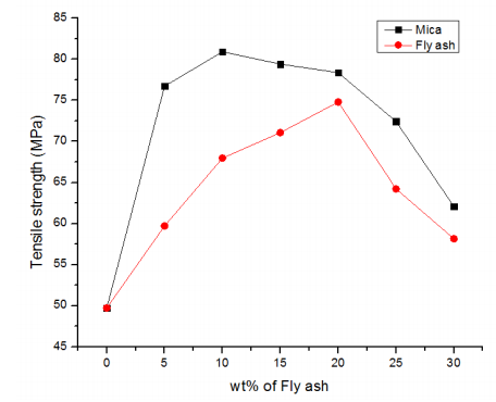
Figure. Tensile strength of PEEK mica and fly ash composites.
As demonstrated in Fig, the tensile modulus of Polyetheretherketone filled composites increased fast as the filler concentration increased. With the addition of filler to the polymer matrix, the tensile modulus rises. The addition of fly ash increases the crystallinity of PEEK fly ash composites, which results in a higher tensile modulus. The tensile modulus of PEEK mica composites grew steadily as the weight percent of mica was increased. The effect of the extent of hydrogen bonding as well as intermolecular interaction of matrix and filler may be seen in the variance in the rate of change of increase in tensile modulus.
As shown in Fig, the elongation at break of PEEK filled composites decreased as the filler concentration increased for both fly ash and mica. The rate of decrease in elongation at break of PEEK fly ash composites was faster than that of PEEK mica composites, indicating that composite brittleness increased with fly ash presence. Because of its platy structure, mica particles provide reinforcement. The hardness of the material reduced as the amount of fly ash in it increased. This could be owing to the agglomeration of fly ash, which serves as the fracture initiation point; this is consistent with the overall pattern of elongation decreasing as filler content increases.
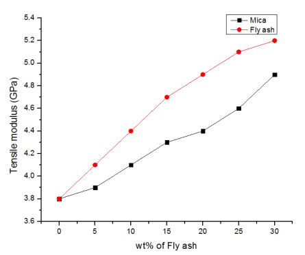
Figure. Tensile modulus of PEEK mica and fly ash composites.
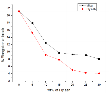
Figure. Elongation at break of PEEK mica and fly ash composites.
As demonstrated in Fig 4, the flexural modulus of filled Polyetheretherketone composites rose as the filler content increased. Flexural modulus increased up to 20% in PEEK fly ash composites before dropping due to increasing fly ash loading, indicating agglomeration. The modulus of a filled system is widely known to be dependent on the properties of the components, fillers, and matrix; fly ash has a greater modulus than the matrix, and filled composites have higher flexural moduli than polymer resin. The addition of mica to PEEK enhanced its flexural modulus constantly. Mica-filled Polyetheretherketone composites boosted their flexural strength by up to 20%. The flexural strength of PEEK mica and fly ash composites is shown in Figure 5. In the case of fly ash, the flexural strength was increased up to 20% but thereafter dropped.
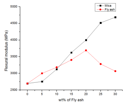
Figure. Flexural modulus of PEEK mica and fly ash composites.
The Charpy impact test is a high-speed fracture test that determines how much energy it takes to shatter a specimen while it is banded. The specimen deforms quickly and is thus subjected to a lot of strain. Since the Charpy impact strength improved, the reinforcing seemed to be highly effective up to 15% mica. As seen in Fig 6, the impact strength dropped sharply after 15 wt% mica was added. The Charpy impact strength of all PEEK fly ash composites is lower than that of virgin PEEK, as seen in the figure. Fly ash causes composites to shatter more easily and make them more brittle. The inhomogeneous particle shape and size of micro particles could be causing the rise in toughness. Because mica particles' edges have varied angularities, they would be more prone to failure under impact due to localized stress concentrations.
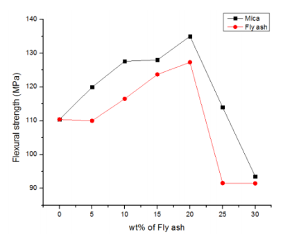
Figure. Flexural strength of PEEK mica and fly ash composites.
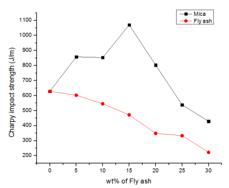
Figure. Charpy impact strength of PEEK mica and fly ash composites.
- Limiting Oxygen Index (LOI)
The LOI is the minimal percentage of oxygen in an oxygen-nitrogen mixture required to start and sustain three minutes of burning. As shown in Fig 7, adding 30 wt% mica to PEEK increased the LOI by 24%, while adding 30 wt% fly ash increased the LOI by 11%. As a result, the fillers reduced the flammability of composites. The deposition of silicate on the surface of the burning specimen causes this phenomenon, which acts as a proactive barrier to heat and mass transport.
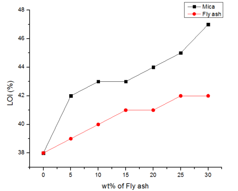
Figure. Limiting oxygen index of PEEK mica and fly ash composite.
2. Modulated Differential Scanning Calorimeter (MDSC)
MDSC was used to investigate the non-isothermal crystallization behaviour of PEEK mica composites, which were cooled from 400 to 40 °C at a constant cooling rate of 20 °C/min. The melting values (Tm) of both filled and unfilled samples of mica and fly ash PEEK composites do not differ significantly, as shown in Fig 8. Melting temperatures for PEEK resin are regularly dispersed between the normal range of 330-385 °C. The glass transition, exothermic crystallization peak, and endothermic peak of crystalline phase melting can all be seen in MDSC thermograms for PEEK mica and fly ash composites. It is possible to measure the volume fraction crystallinity of matrix by measuring these peak regions.

Xv = Volume fraction crystallinity.
Hm = heat of fusion measured as the area of melting peak.
Hc = heat of additional crystallization measured as the area under the crystallization peak.
Hf = theoretical heat of fusion for a pure crystalline phase for PEEK 130 J/g.
ρa = density of amorphous phase for PEEK 1.2626 g/cm3
ρc = density of crystalline phase for PEEK 1.4006 g/cm3
Xms= mass fraction of reinforcement.
Table 1 shows the Xv values for composites filled with the same amount of mica and fly ash. This could be owing to the finer particles obstructing the extension of PEEK crystalline segments to a lesser extent. The improved crystal nucleation in the region surrounding the reinforced particles is responsible for the rise in perfection or crystallinity [14, 15]. The better interaction between PEEK and mica particles is evidenced by the greater percentage crystallinity for 20 wt percent of 44m size mica PEEK composite. The degree of crystallinity of PEEK fly ash grows continuously with the addition of fly ash, as illustrated in Fig 8. The fillers had little effect on the Tg and Tm of PEEK composites, although crystallization temperature increased at low concentrations (10 wt percent) of fly ash and mica, then reduced, as shown in Fig.
Table 1 shows PEEK-filled fly ash and Hm, Hc, and percent crystallinity mica (Xv)
Materials |  |  |  |
VPEEK | 16.79 | 37.20 | 39.04 |
10FA44* | 19.37 | 28.81 | 38.70 |
20FA44 | 22.65 | 27.79 | 4593 |
30FA44 | 21.97 | 25.43 | 49.51 |
10M44** | 22.35 | 28.44 | 40.06 |
30M44 | 14.82 | 18.84 | 34.61 |
*10 wt% fly ash 44µm filled PEEK composite, **10 wt% mica of 44µ filled PEEK composite. Similarly 20, 30 withstand 20% and 30% fly ash and mica
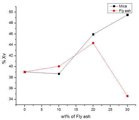
Figure. Degree of crystallinity of PEEK mica and fly ash composites.
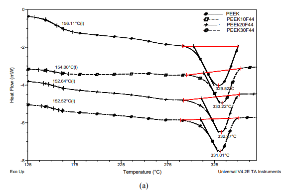
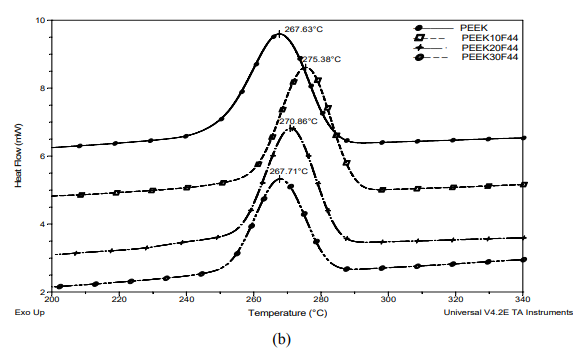
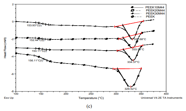
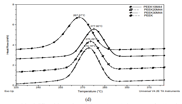
Figure. Modulated differential scanning calorimeter (MDSC) thermograms for (a) and (c) second heating curves of Tg and Tm of 44 µm mica filled PEEK composites. (b) and (d) cooling curves of crystallization temperature Tc of 44 µm mica filled PEEK composites.
3. Dynamic Mechanical and Thermal Analysis (DMTA)
E' vs temperature for PEEK reinforced with 0–30 wt% mica is shown in Fig 10 (a). E' rose when mica in the PEEK matrix increased, as expected. Above Tg, mica had a stronger reinforcing effect. This was similar to a recent investigation of AlN/PEEK composites [16], which found that the modulus increased as the filler quantity increased. However, this was not the case with a short-carbon-fiber-reinforced/poly (ether ether ketone) (SCFR– PEEK) composite, in which the modulus increased fast below Tg before rapidly decreasing as in pure PEEK [17]. The content of mica used in PEEK mica composites affects the modulus, especially at low temperatures. The E' of mica filled PEEK composites increases as the mica concentration increases at 50 °C. This suggests that adding mica to the composite increased its stiffness, and the reliance of E' on filler loading is more obvious in the glassy area. For all of the specimens, the decline in storage modulus with temperature during the transition from glassy to rubbery state occurred about 150 °C. Mica loading in PEEK had no effect on the glass transition temperatures according to storage modulus. At 50 °C, the storage modulus of PEEK filled 20 wt% composites is enhanced by 61% when compared to pure PEEK. Because of the high modulus of mica and the good contact between the mica and the matrix, which inhibits the segmental motion of the PEEK molecules, the modulus rose. These findings indicated that load was effectively transferred from the matrix to the mica. The uniformly scattered mica particles in the matrix, which enhanced the interfacial area between mica and the PEEK matrix, may have contributed to the considerable improvement in E' in this work. The temperature dependences of the storage modulus of PEEK composites with a fly ash loading of 0-30 wt% are shown in Fig 10 (b). When compared to pure PEEK, the E' has improved by 143 percent at 30 wt% fly ash at 200 °C. Fly ash in PEEK improves the high temperature performance of PEEK composites.
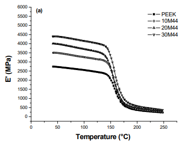
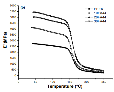
Figure. Dynamic mechanical spectrum of storage modulus of (a) PEEK mica composites and (b) PEEK fly ash composites.
4. Scanning Electron Microscopy (SEM)
SEM was used to investigate the morphology and particle distribution of PEEK mica and fly ash composites. Figure 11 shows a micrograph of PEEK mica and a micrograph of PEEK fly ash particles, respectively. The mica particles are uniformly scattered inside the PEEK matrix, and there are no filler particle aggregates visible. This supports the idea that the composite with 20% mica had better characteristics than PEEK fly ash composites. In the PEEK matrix, the mica particles were similarly more strengthened than the fly ash particles, as shown in the micrograph.
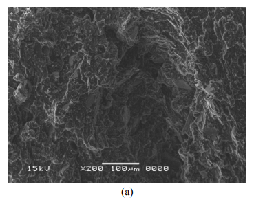
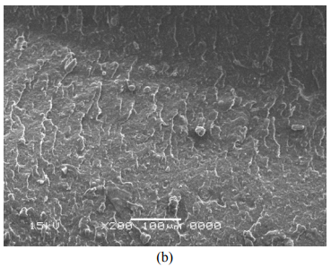
Figure. SEM image of (a) 20 wt% mica of 44µm filled PEEK composite, (b) 20 wt% fly as of 44µm filled PEEK composite.
CONCLUSIONS
The following conclusions were reached as a result of the research.
The inclusion of 5- 30 wt% filler increased the tensile modulus of PEEK fly ash and mica composites. The tensile modulus of the fly ash loaded PEEK composites was higher than that of mica. The mixture of 20 wt% fly ash and mica filled PEEK produced the best strength enhancement. The tensile and flexural strength of the material declined as the number of fillers (30 wt%) increased, whereas the tensile modulus rose continuously. The use of mica in PEEK composites improved the charpy impact strength, whereas the impact strength of fly ash composites dropped. The limiting oxygen index of PEEK loaded with fly ash and mica improved dramatically. PEEK mica composites have a greater LOI than PEEK fly ash composites. Mica outperformed fly ash in terms of overall reinforcing qualities.
4.8.2 Recycling of Polymer Matrix Composites
In its most basic form, a composite material is made up of at least two joined constituents that work together to create a material with better qualities. In practice, most composites are made up of a bulk material (the matrix) and some form of reinforcement, which is added to boost the matrix's strength and stiffness. This reinforcement can take the shape of fibres. Polymer matrix composites (PMCs), metal matrix composites (MMCs), and ceramic matrix composites (CMCs) are the three most frequent types of man-made composites today. Polymer matrix composites are competitive because of their lightness and mechanical strength, as well as their low relative production cost, which allows them to replace traditional materials like wood and metal. The thermoset resin and the fibre make up the PRGF composite, which is an engineering material. In the moulding process, the liquid resin is mixed with the fibre and cures creating a solid laminate. There are numerous different types of composite resins and reinforcements, and each one gives the PRGF product its own set of characteristics. The resin system is chosen depending on the product's functional and economical requirements. Although a variety of reinforcing fibres are employed in composites, the PRGF contributes more than 90% of the total amount of produced polymer matrix composites. PRGF composites have a high degree of adaptability and can be used in a wide range of applications. It has a wide range of applications, from roof tiles to vehicle parts. However, from an ecological standpoint, it is problematic. The thermoset matrix composites sector in Brazil is estimated to generate 10,000 tonnes of solid waste per year, which is typically disposed of in sanitary and industrial embankments [2]. Figure 1 shows that the amount recycled is less than 1% of the total created, excluding post-consumed items. The solid residues formed during the manufacturing of PRGF goods, as well as the post consumed products, must be properly managed (collection, packaging, transport, treatment, and/or final disposition). This is done in order to minimize environmental damage while simultaneously protecting people's health and wellbeing. While the usage of thermoplastics for packing results in hundreds of tonnes of solid waste each year, the thermoset polymer composite material creates only a fraction of that. The non-melting resin utilized as a matrix, however, is an aggravating problem. It is also necessary to evaluate the projected expansion of this material's use in the Brazilian market. The entry of foreign resin-producing industries corroborates this.
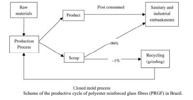
Figure shows the various management options for PRGF waste recycling. Chemical recycling, energy recovery, and mechanical recycling are the most often available options for recycling PRGF.
Energy recovery
Because hydrocarbon polymers substitute fossil fuels and so lessen the CO2 impact on the environment, energy generation from plastic trash incineration is in principle a viable use for recovered waste polymers. Table 1 compares the calorific ratings of various polymers to those of conventional fuels. The fibres, on the other hand, are more valuable than the energy content of the polymers in fibre reinforced thermoset composites.
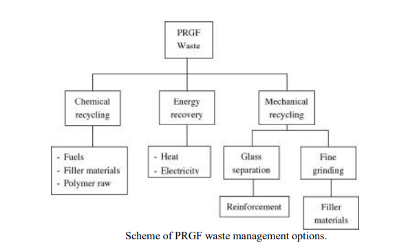
Fuel | Calorific value(MJ/kg) |
Methane | 53 |
Gasoline | 46 |
Fuel oil | 43 |
Coal | 30 |
Polyethylene | -43 |
Mixed plastics | 30-40 |
Municipal waste | -10 |
Chemical recycling
Pyrolysis, hydrogenation, and cracking are the three basic types of chemical PRGF recycling processes. • Pyrolysis is the breakdown of pyrolysis. This method involves the thermal breakdown of organic compounds at temperatures ranging from 400 to 800 degrees Celsius. The material is burned in the absence of oxygen or at a very low oxygen level, yielding up to 50% gas (hydrocarbons, ammonia, and chloride of hydrogen), as well as 25-40% oil (Syncrude) and solid leftovers.
Hydrogenation
The material is treated in a hydrogen environment at temperatures ranging from 300 to 500 degrees Celsius and pressures ranging from 100 to 400 bar, yielding 65-90 percent oil (Syncrude), 10-20 percent gases, and up to 20% solid residues.
Cracking.
To create oligomeric waxy liquids suitable for further catalytic cracking, the material is heated to 400°C to 600°C and at pressures slightly over atmospheric. The gases that are produced are used to power the operation.
Mechanical recycling
The Powder Processing Centre - CPP is particularly interested in mechanically grinding PRGF composites for recycling. Glass separation and fine grinding are two types of mechanical recycling processes.
Glass separation
The composite scrap must first be reduced to a size and shape that permits for efficient transportation and handling. The shopped material is then processed. The polymer breaks down and burns when composite materials are treated in a fluidized bed at high temperatures. This causes fibres and any filler in the fluidized bed to be transported out into the gas stream. A cyclone, for example, can remove the fibres and fillers from the gas stream. The recovered fibre has some recycling value, but it is lower than virgin fibres for several reasons: the fibre length is no longer uniform or of the same size; the glass will no longer wet out as quickly as virgin fibre glass; the glass has filler and resin attached, reducing the weight of fibre per weight used; and the recovered fibres have about half the strength of virgin glass fibres.
Fine grinding
This entails reducing PRGF scraps and process chips to particles with a diameter of around 200 m. This is accomplished via grinding, and the resulting fine material is utilized as a filler. The grinding process includes size reduction of pieces measuring 50 x 200 mm, grinding in an attrition mill, particle classification (particle size distribution), and particulate material treatment. This path, however, has certain drawbacks. It is difficult to grind the Fiberglas in the system [7]. To avoid short curing durations, the chemical reactivity of the particle material (resin and particle) must be decreased (hardening).
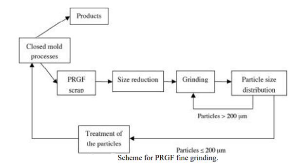
Fillers, concrete reinforcement, asphalt reinforcement, energy source, and oil are some of the uses for PRGF scrap. The filler is mostly employed in the composition of items made using closed mould methods. Its purpose is to save money by replacing the more expensive resin with a less expensive one, while also increasing properties like rigidity and thermal expansion. It's worth noting that, unlike the open mould technique, the filler is widely used in the closed mould method. The residue of PRGF is utilized as reinforcement in concrete and asphalt. However, due to a lack of rules, this use has not yet become widespread. It is feasible to obtain energy equivalent to that of fuel oils by incineration as a source of energy. It is possible to make xylem, benzene, and toluene from oil acquired through chemical recycling methods (pyrolysis, hydrogenation, and cracking). Those procedures are extremely costly.
Key takeaways:
• Polyetheretherketone (PEEK) is a semicrystalline high-performance polymer with exceptional thermal stability, wear resistance, mechanical characteristics, and chemical resistance.
• Has a high melting point (Tm), a glass transition temperature (Tg), and a constant service temperature.
Natural, renewable, environmentally friendly, and sustainable materials have become increasingly important in polymer science and engineering over the last few decades. This branch of research was expected to excel at producing valued products with fewer carbon footprints and environmental effects. The use of organic materials in polymers to improve their properties has piqued the interest of scientists and even large-scale industries in this context. These techniques could be a viable alternative to non-renewable resources or synthetic chemicals. In comparison to its counterparts such as chitin, alginate, and chitosan, cellulose is by far the most abundant renewable organic compound on Earth. Natural sources of cellulose, such as plants, algae, bacteria, and tunicates, could be isolated using appropriate methods. This compound also has a lot of potential for being modified, functionalized, and tailored to improve its specific properties for the applications it's designed for. When cellulosic chains are bundled together, highly ordered structures are created (cellulose nanoparticles). Because of their unique physicochemical properties such as hydrophilicity, chirality, biocompatibility, and biodegradability, these nanoparticles are widely regarded as a “green” compound of the future. Chemical resistance, high stiffness, low density, dimensional stability, low cost, non-abrasiveness, and good adaptability to surface modifications through chemical reactions are some of the other benefits of cellulose and its derivatives.
Elastomers, on the other hand, are materials with a molecular structure that makes them elastic and extensible. This class of materials is characterized by an amorphous structure and a low modulus. Elastomeric materials include, but are not limited to, all types of rubber from both natural and synthetic sources, thermoplastics, silicones, and ethylene-vinyl acetate. Rubbers are a large subset of this elastomeric materials class. Since the twentieth century, Southeast Asian regions have dominated rubber-based industries, with Malaysia serving as the world's largest producer and exporter of natural rubber. Thailand currently holds the number one position, followed by Indonesia and Vietnam. The majority of resources, including natural rubber latex, rubber variants, and rubber-based products, are exported to China, Europe, and the United States. Rubber is used in a variety of industries, including automotive, machinery, aerospace, adhesives, electrical and electronics, chemicals, and, increasingly, healthcare. Rubber's multifunctionality and compatibility are being explored daily in a variety of applications, resulting in rising global demand.
Rubber is considered a large group of polymers that are used as a subset of elastomers. The elastomer with longest history of the application is cis-1,4-polyisoprene, or more commonly known as the polymer constituent of natural rubber (NR). Natural rubber can be obtained from milky, slightly dense and viscous latex obtained from lactifier-developed in plants of over 2500 species. The NR latex is derived from Hevea brasiliensis originated from Brazil but is now widely cultivated in Southeast Asia. Other source of NR latex includes Parthenium argentatum from Mexico, Taraxacum koksaghyz from Russia, Solidago altissima from Canada and the United States, Eucommia ulmoides from China, as well as in Dyera costulata from Thailand and Malaysia.
Recently, newly emerging commercial products begin to change from using NR to other synthetic materials. However, as an industrial commodity, NR possesses physical and chemical properties that cannot be fully mimicked by synthetic rubber. Nevertheless, the uses and economy of synthetic rubber are also blooming due to its variety and adaptability for numerous applications while competing with its natural counterpart. Generally, synthetic rubbers are manufactured from byproducts of the petroleum industry, fossil fuel resources and natural gas. For example, one of the byproducts, naphtha, is thermally cracked to produce olefinic monomers, subsequently bonded together with the addition of chemicals, and then undergoes the process of polymerization to produce rubber polymers. Common synthetic rubber types include styrene-butadiene rubber (SBR), polybutadiene rubber (BR), chloroprene rubber (CR), acrylonitrile-butadiene rubber (NBR) and its carboxylated variant (XNBR), silicone rubber (SR) and isoprene rubber (IR). Each type of synthetic rubber has different chemical structures and protruding functional groups so that they could be tailored to excel in certain properties. Some synthetic rubbers such as ethylene-propylene rubber possess excellent heat resistance with the ability to withstand service temperatures of approximately 150 ℃, while NBR is reported to have notable swelling resistance towards hydrocarbon oil. Like NR, synthetic rubber has also found its way in a myriad of industries and applications such as in aerospace, footwear, healthcare equipment and devices, personal protective equipment, toys, latex-based paints, sealants, adhesives and belts for mechanical parts. Both NR and synthetic rubber have their own attracting factors. Hence the selection of material greatly depends on the intended application. Figure shows a summarized processing chain for NR and synthetic rubber which could then be employed in various applications.
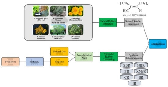
Figure. Summarized process chain for natural and synthetic rubber.
With all of the excitement surrounding rubber's success on the global market, it's thought that the agricultural industry might be able to supply enough feedstock for both polymer and filler materials. The use of fillers in vulcanized rubber is a complicated topic that engineers, scientists, and rubber technologists are constantly researching. Various cheaper fillers, such as clay, mica, and calcium carbonate, are used in the rubber compounding process to keep the final product cost down. These fillers are referred to as "non-reinforcing" because they have little impact on the composite's mechanical performance. Furthermore, such fillers may have an impact on processing efficiency by altering the manufacturing and functional properties of vulcanizates. Fillers like carbon black (CB), silica, and talc, on the other hand, are used as reinforcing agents to improve mechanical and strength-related properties like tensile strength and elasticity before fracture. Vulcanizates must be reinforced with fillers because they are mechanically weak and difficult to process. Figure 2 shows a general classification of rubber fillers. The size and surface area of the particles have a significant impact on the reinforcing performance of fillers. Due to increased effective surface area and improved interfacial interactions with the rubber matrix, the reinforcing effect increases as the size of the reinforcing particles decreases. The size ranges smaller than 1000 nm were classified as semi-reinforcing, while those smaller than 100 nm, known as nanofillers, had more significant reinforcing performance. When particle sizes exceed 10,000 nm, which is typically larger than the polymer interchain distance, the filler can cause delocalized stress, which can lead to elastomeric chain ruptures when bending, stretching, or flexing.
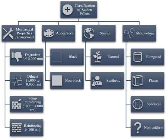
Figure. General classification of fillers for rubber sources.
The use of traditional fillers like CB and silica has environmental and energy-related drawbacks. As a result, more sustainable natural alternatives are required. In rubber-based research groups and large-scale industries, the search for substitutes and alternatives to conventional fillers is the driving force in research and development. Nanocellulose has recently demonstrated its ability to match or exceed the current reinforcing performance of conventional fillers.
As a result, the goal of this review is to provide a summary of recent studies on the reinforcement of rubber matrices with various forms of cellulose and the mechanical benefits that result. First, a brief overview of rubber variants and traditional fillers will be presented. Following that, an introduction to cellulose and its various types in terms of structure, size, and sources would be given. Following that, recent advances in cellulosic surface modification for rubber reinforcement applications would be discussed. This would be in relation to improvements or breakthroughs in mechanical performance achieved by using nanocellulose as a rubber filler. We would discuss current developments or future applications of nanocellulose in a separate section to inform readers about the potential of organic fillers as a long-term reinforcing agent in rubber. Finally, some thoughts on the future of this innovative technology and how incorporating cellulose into the rubber industry could benefit all parties involved would be offered as a closing remark.
Conventional Rubber Fillers for Mechanical Reinforcement
NR is a natural polymer with exceptional properties such as high tensile strength after vulcanization (curing) due to its ability to spontaneously crystallize when strained. For their intended applications, other properties such as modulus, abrasion resistance, and hardness require assistance. Carbon black (CB) and silica are the two pioneer members of conventional particulate fillers for rubber specifically for mechanical reinforcement, with the former being used first in rubber industries. Since the 1920s, these fillers have been widely used to improve the mechanical properties of a variety of rubbers. Rubber reinforced with CB has a higher modulus than rubber reinforced with silica, but the latter offers a more comprehensive and holistic improvement in tear strength and adhesion properties for a broader range of applications.
Carbon Black (CB)
The addition of CB to rubber compounds is used to strengthen the intermolecular bonds between the molecules that make up the compound. Due to its small particle size and multiple functional groups, CB also helps to maximize volume, improve the physical properties of the rubber, and improve vulcanization, as shown in Figure 3. Meanwhile, the use of CB reduces the rubber's stickiness, which may be beneficial in some applications. Despite this, CB is still considered a pioneer member and is widely used in large-scale rubber processing industries.
CB is a carbonaceous material found in near-pure form as a byproduct of hydrocarbon fuel or biomass processing. It contains over 98 percent elemental carbon, which is made up of spherical carbon atoms that clump together. During rubber processing and compounding, these aggregates can form agglomerates that break apart. CB particle diameters can range from 10 nm to 500 nm, depending on the source. This variation can be attributed to a number of factors, including the temperature of the processing combustion and the duration of the combustion. It was also determined that CB particle sizes greater than 1000 nm do not help rubber reinforcement but can be used to increase latex viscosity due to hydrodynamic and Payne effects. CB has a more graphitic structure as a result of these large sizes. Because of the diversity of this material, different types of CB have emerged, including furnace black, thermal black, acetylene black, channel black, and lampblack. Because CB particles are mostly found in aggregates rather than as individual particles, their three-dimensional arrangement determines the CB's structure, which is classified according to ASTM D1765 nomenclature. Table 1 lists common CB varieties, as well as their mean particle sizes and nitrogen surface areas.
Other elements such as hydrogen, oxygen, nitrogen, and Sulphur are also present in rubber-grade CB, according to a detailed chemical analysis. These elements' compositions vary depending on the fuel source and are minor but not insignificant. Because CB is made from hydrocarbon fuels, the dangling bonds at the graphitic planes' terminal edges, which are made up of large polycyclic aromatic rings, are saturated with hydrogen atoms. All protruding surface functional groups contain oxygen, which affects the physicochemical properties of CB, such as chemical interaction reactivity and attachment potential. In the context of rubber processing, CB surface oxidation lowers pH and alters the vulcanization kinetics. CB and rubber compounds have a strong chemical interaction that could help in two ways: breaking up agglomerates during the mixing step and preventing particle re-agglomeration. The presence of sulphur, olefins, and radicals, as well as large amounts of reactive carbon–carbon double bonds, indirectly help to reinforce the rubber material's cohesiveness. Because of the anisometric structure of CB aggregates, mechanical interlocking of rubber polymer chains with CB is possible. When uncured rubber is homogeneously blended with CB, the rubber chains are bound to the CB aggregates in a variety of ways, including physical and chemical interactions, chain immobilization through the creation of glassy-like bridges between filler particles, and mechanical interlocking of rubber chains around the filler surface, forming a rubber shell. The last mechanism renders the bounded portion of the rubber inelastic (occluded rubber), but increases the effective filler volume indirectly as rigid particles. In conclusion, mechanical interlocking of polymeric chains onto CB surfaces, chemisorption reactions, and van der Waals forces between CB and rubber all contribute to CB's reinforcing activity.

Figure Structure of CB and its typical surface functional groups. Adapted with permission from. Copyright 2003 John Wiley & Sons.
Silica
Precipitated silica has been used as a filler in passenger car tyres as a result of the success of CB. Since Michelin's introduction of "Green Tires" in the early 1990s, the technology for using silica in tyres has been developing. It was determined that replacing CB with silica would save energy during logistics as well as improve the recycling process of used tyres at end-of-life cycles. When compared to CB-filled tyres, this technology claims a 3% fuel savings due to a 20% reduction in rolling resistance. Significant mechanical properties, exceptional rolling resistance, high resilience, and slow heat build-up are all advantages of using silica as a reinforcing agent in rubber. If the rubber is polar and functionalized, silica technology could be used directly. Due to the polarity differences between the two, coupling agents such as silane are required in the case of nonpolar and non-functionalized rubber.
From a chemical standpoint, silica's surface is coated with polar and chemically reactive silanol groups. Because of its low compatibility with hydrocarbon rubbers, this group is difficult to process. As a result, the filler-rubber interactions would be weak, and silica would not perform as well as it could. Filler-rubber interactions and filler dispersion in the rubber matrix are significantly improved by silane coupling agents. Silica aggregates form a network mesh in rubbers filled with silica-silane compounds, trapping occluded rubber through hydrogen bonding. A coating of bound rubber would be formed chemically around the silica aggregates using silane coupling agents. Simultaneously, due to the surface adsorption of rubber chains on the modified surface, some weak silica-rubber interactions may occur. The filler network breaks open during deformation, exposing the occluded rubber and causing matrix deformities. Rubber chains attached to the silica surface and occluded rubber, on the other hand, remain intact with the addition of coupling agents, proving its mechanical integrity. Majesté and Vincent conducted research that linked the rate at which aggregate surfaces were covered by physically adsorbed rubber with reinforcement indicators, demonstrating the evolution of rubber reinforcement over time. It was discovered that strong filler-filler interactions are being replaced by weaker filler-rubber interactions. Increasing the content of coupling agents improves the overall reinforcement index, but only to a point. Chemically bonded rubber contents plateau once silane content in coupling agents approaches 10% wt%, according to experiments by Kaewsakul et al. Functionalizing rubber compounds with polar groups, grafting silica surfaces, combining it with CB, making hybrid fillers with graphene nanoplatelets, and synthesizing novel silica with high dispersity are some of the other methods for improving silica compatibility with rubber.
Introduction
Fibre reinforced polymers are being used more and more in components that are subjected to high dynamic loads. In aircraft and vehicle design, as well as machine tool engineering, robotics, and general mechanical engineering, a wide range of applications can be found. In order to improve material damping, fibre composite technology allows the customer to choose the material combinations, fibre orientations, and composite lay-up. To produce large, single components, new manufacturing technologies based on fibre composites are required for economic reasons. The number of joints between structural components is kept to a minimum. New damping concepts are required for the design of structures made of fibre composites because they usually determine favourable vibration behaviour. The most important damping characteristics of an elementary single layer made of fibre composites in-axis and off-axis are determined in this paper using a practical procedure. The method is based on resonance frequency results that have been extended to include bending, torsional, and longitudinal oscillators. Furthermore, analysis methods for the design of multilayer composites optimized for damping and stiffness are described. The correspondence principle of the theory of linear viscoelasticity is used in the mathematical—mechanical modelling. As a starting point, the model is applied to a unidirectional composite as a basic element. Following that, the concept of complex moduli is used to determine and optimize the stiffness and damping characteristics of multilayer fibre composites. The knowledge of the material properties of the UD layer, from which the anisotropic composite properties are derived, is the foundation for structural optimization. Temperature and humidity have an impact on material properties and must be taken into account.
Experimental Procedure for Determination of Damping Characteristics
The fading of vibrations is known as damping in technical constructions. The mechanical (kinetic) energy in the system is converted into heat here. Material damping refers to the dissipation processes that occur within materials. On the basis of harmonic stresses and deformations, material damping is introduced into elastic deformation conditions. Assuming harmonic stresses o*(t, co) =o*(w)-e"”’ and corresponding strains 8*(t, w) =e*((o)-e'“” and with the assumption of the theory of linear viscoelasticity the following one—dimensional material law can be defined:
6*(00) E*(0)) ~e*(o)) (E’(oa)+i’E"(w)) ~e*(w) E’(oo)«(1+i-d(w))-e*(w) (1)
With d(o)) as material damping and ’(w) as the dynamical Young’s modulus or energy storage modulus. (E "((0) is called loss modulus). 91This is one way to describe linear viscoelastic material behaviour, other methods like e.g. The energy method are also possible. For common fibre volume contents of 50 to 60% and with comparably low strain level in the structure, linear damping mechanisms predominate in most cases (Ehrenstein, 1998; Tauchert, 1974). Thus, in the following linear damping d((n) will be considered exclusively where the reinforcing fibre shows linear elastic behaviour and the polymer matrix is linearly viscoelastic. If synthetic fibres, e.g. Aramide, are used as reinforcing material, the fibres also show damping. Corresponding approaches are available in the literature. In order to determine the damping characteristics of polymer fibre composites specific resonance method with small strain amplitudes (£<0,001) was developed for the above mentioned linear relations. With this resonance method damping and corresponding dynamical properties of samples with rectangular cross-sections can be simultaneously determined for bending and torsional vibrations. In the experimental set up cantilever bar is excited to bending and torsional vibrations at adjustable temperature (Figure 1). The excitation is realized by an excentric force (t) generated by an inductive shaker. Next to the clamping the vibration (1000) is measured by means of an eddy current sensor.
Longitudinal vibrations can be applied in corresponding set up. Here the sample bar is freely suspended by filaments and two identical masses are fixed to its ends to lower the natural frequencies. Longitudinal vibrations are broadband excited by means of an electromagnetic shaker and the response is measured by an accelerometer. In both cases the signal processing is performed with suitable amplifier technology and Fourier analyser.
Evaluation of the material characteristics from the resonance diagram is based on the equations of motion for weakly dampened bending w (x, t), torsional 13(x, t), and longitudinal u (x‚ t) Vibrations. For cantilever bar of rectangular cross-section with the dimensions bx they read 84w(x t) 82w(x,t) E’1+d I.—’ bh—=O (2) B) -‘ 8x4 aß 8219m 192m2 820 G’(l+sz)I,#+rth%=0 (3) E’(1+idL)—————a ”(QMM —a“0”) =0 (4) at2
Results of Experimental Investigations
Temperature Influence on the Damping Characteristics
Polymer materials show material properties which strongly depend on temperature and frequency. In glass state they have high storage modulus but low damping. With increasing temperature, the degree of damping shows several maxima, each of which is combined with change in the modulus. In the range of softening, substantial decrease of the storage modulus appears whereas the damping shows maximum. The frequency gains considerable influence on the damping and stiffness behaviour. In this case, highest molecule mobility occurs at the temperature of maximum damping. The beginning of the steep decline of the storage modulus generally represents the limit of technical application of (fibre reinforced) polymers; it is named glass transition point. The position of the glass transition point depends on the frequency and on the absorbed humidity. Water absorption in polymer materials results in change in viscoelastic behaviour. In the case of constant frequency higher humidity reduces the glass transition point to lower temperatures and at constant temperature transition occurs at shorter cycle times or at higher frequencies, respectively.
Influence of Humidity
Humidity is an environmental parameter which has to be considered for the analysis of (dynamically) loaded fibre composite structures. Polymere matrices and synthetic fibres absorb moisture from the environment. The amount of absorbed water depends on time. Surrounding humidity and the diffusion coefficient of the material. Regarding glass and carbon fibre reinforced polymers humidity leads to degradation of the matrix dependent strength and stiffness properties. If synthetic fibres are used as reinforcing material also the fibre dependent properties are affected. On the other hand higher humidity increases the maximum allowable strain of the polymere material. The humidity influence on the damping behaviour of fibre composites is determined by means of the resonance bending test. Unidirectionally fibre reinforced samples (material: 6376-T400), conditioned with 0% and 75% relative humidity, were tested at fibre angles of 0:0". 0:45° and 0=90°. The direction depending damping and stiffness behaviour of the dry and humid layer is compared in polar diagram. It shows the variation of the damping factor (11 and the memory modulus E’l with varying fibre angle where the functions between the measured values are obtained by transformation analysis. Only one quarter of the double symmetric polar diagram is significant. For all reinforcing directions relative humidity of 75% increases the damping by factor of two whereas stiffness is reduced by approx. 20%. In humid laminates the damping maximum shifts to 0=39° from 0=4S° for the dry ones. It can be concluded that the damping characteristics of dynamically loaded fibre composite structures are improved considerably by the influence of humidity. Therefore, using damping characteristics obtained under dry conditions leads to conservative results. The shift of the damping maximum towards smaller fibre angles even increases the potential of optimization.
Determination of Material Damping for Multi-Layer Fibre Composites
Glass fibre reinforced (GF) plastics with matrix of epoxy resin (EP) and carbon fibre reinforced (CF) plastics with matrices of epoxy resin and Bismaleinimid (BMI) were selected from the great number of fibre matrix combinations available for lightweight construction. With these materials multilayer composite structures can be set up using uni-directionally (UD) reinforced prepregs. In Table the static and dynamic characteristics of the investigated UD laminates are summarized.
Material EP/GF-UD EP/CF-UD BMI/CF-UD
Components E-glass EPLY556 T400 EP 6376 800 BMI 5245 HT 976
Young‘s modulus [GPa] 73 3,5 250 3,3 294 3,3
Poisson number 0,18 0,35 0,24 0,36 0,23 0,33
Density [kg/m3] 2520 1220 1800 1230 1810 1250
Strain to failure EBr [%] 2,5 1,5 3,2
Composite UD (10:1) UD UD
Fibre vol. Fraction (p [%] 56+1‚0 56+1,0 62+1,0
Young‘s moduli static dynamic static dynamic static dynamic
E1 [GPa] (axial) 41 33,5 137,16 94,79 175 94
E2 [GPa] (transversal) 15 14 9,14 7,8 12 6,4
v12 0,24 0,2914 0,32
G12 [GPa] 3,6 4,7 19 [5,28 4,6
Damping
d1 (axial) [%] 0,1875 0,1726 0,0835
d2 (transversal) [%] 0,6988 0,7158 0,3249
Du (shear) [%] 1,1662 0,8204 0,3510
Table 1. Characteristics of the Investigated Materials
For simplicity reasons the single layer is described as uniform continuum with anisotropic, linear viscoelastic properties. To introduce the damping to fibre composites the concept of the complex moduli is applied to the constitutive (material) equations by replacing the elementary elastic constants by their corresponding viscoelastic ones.
Carbon Fibres as Reinforcing Material
Compared to other materials carbon fibres show small damping properties but very high stiffness. In order to identify the influence of different fibre types (T300, T800, and M46) on the damping and stiffness behaviour and their directional dependency they are measured for single unidirectionally reinforced layer using the same matrix (LY556/HT976). High fibre volume content of (p=70% was chosen so that the small differences in fibre damping are not fully covered by the viscoelastic behave.
In fibre direction only small deviations in damping are recognizable, whereas great differences occur with increasing fibre angles. The highest energy absorption can be achieved with the high-tensile carbon fibre T800. The damping is 13% larger than those of the laminate with the fibre T300 and 22% larger as compared to the unidirectional composite with the high modulus carbon fibre M46. The increase in damping with increasing fibre angle is equal for both high-tensile fibre types up to an angle of 0:300 while for the high-modulus fibre the gradient is higher. Maximum damping for the fibre T800 is reached at fibre orientation of 0=90°, for the fibre T300 at 6=4S° and for M46 at 0:34°. Variation of the stiffness with fibre angle makes obvious the significant anisotropy of the laminates. The laminate with the high-modulus fibre M46 shows almost double the storage modulus in fibre direction as compared to that with the fibre T300. Nevertheless, the influence of the different reinforcing fibres can be neglected already at fibre angle of 0=20°. The laminate with the high-modulus fibre even shows the lowest storage modulus at 6:90°. It becomes clear that the dynamic behaviour of the carbon fibre reinforced laminates with low viscoelastic properties can be significantly influenced by the fibre angle.
Influence of Other Reinforcing Fibres
Much higher damping can be achieved with other fibre materials but at the expense of stiffness. In particular synthetic fibre reinforced polymers are characterized by remarkably high energy absorption. Figure shows the dynamic properties storage moduli and damping for the reinforcing materials Aramid fibre and Dyneema fibre embedded in the matrix system LY556/HY917 with low damping. In fibre direction, the Aramid fibre reinforced laminate shows double the energy absorption as compared to the laminate with Dyneema fibre. Perpendicular to the fibre direction the difference is less distinct. The latter composite shows sharp increase of damping with increasing fibre angle. Compared to the Aramid fibre reinforced 98 laminate higher damping can be achieved with fibre angles 6:50 and 6=40°. Considering also its extreme low density (p=970 kg/m3) makes Dyneema very valuable damping material for lightweight structures. Damping of carbon fibre reinforced laminates is very small as compared to Aramid and Dyneema composites. However, with regard to the stiffness carbon fibres are superior.
Influence of the Matrix Material on the Viscoelasticity
The matrix system has minor effect on the elastic properties of fibre composites, whereas its influence on damping is quite high. To illustrate this, matrices with different damping properties (LY556/HT976, 6376 and 5245) were uni-directionally reinforced with the identical fibres (T300) and their damping and stiffness behaviour was examined. The characteristics calculated for fibre volume content. With almost the same stiffness the different matrix materials show considerable differences in damping. For all laminates the maximum damping is at fibre angle of 6:90". The epoxy resin LY556/HT976 shows three time higher damping compared to the modified Bismaleinimid 5245. The mixed matrix material 6376 has 20% lower laminate damping.
Optimization of Laminate Lay-Up
For the considered case of bending vibration the carbon fibre laminate with BMI matrix shows the highest stiffness, whereas the damping capabilities are comparably small. On the other hand, the glass fibre laminate with epoxy matrix has high damping properties but small stiffness. The highest damping can be achieved with the matrix system EP 6376, reinforced with the carbon fibre T400.
All considered laminates show different but qualitatively similar fibre direction depending damping characteristics. Thus, the damping in all examined cases is not at its maximum at fibre orientation 9=90°, but with orientation between 15°SGS45°. Therewith, damping shows similar direction depending behaviour as it is known for the Poisson’s ratio of the UD layer. This can be physically explained by dominant influence of the shear part due to Im on the entire damping potential.
Conclusion
New manufacturing technologies with fibre composites allow to minimize the assembling of different parts. Therefore, material damping must be optimized to maintain desired decay behaviour of the structure. The material damping of fibre composites itself is dependent on different parameters. In this paper suitable damping characteristics and notes for the adjustment of desired damping are given. As expected the calculated and experimentally proved damping behaviour of UD laminates are minimal in fibre direction and generally behave in counter rotation to the stiffness behaviour. Nevertheless, the significant damping maximum does not appear perpendicular to the fibre direction but rather at an intermediate orientation of 15°SGS45°, so that the corresponding points with sufficient stiffness have to be searched for in this range. For instance, the damping can be increase by 130% for specific CFRP angle ply laminate with an insignificant increase in thickness of 6,25% only and with the same stiffness as compared to the UD laminate. In future damping models must be introduced into numeric procedures such as the method of the finite elements (Schrader, 1997). However, since the optimum design of composite laminates requires considerable effort alternative design tools such as the computer program LAMTECH should be considered.
4.11.1 INTRODUCTION
Composite materials and structures experience two distinct external environmental conditions (i) ground (and near ground) environment and (ii) space environment. The former is primarily dominated by the temperature and the humidity. The presence of oxygen, sodium chloride, sulphuric acid and certain other aggressive chemicals in the lower atmosphere is also of major concern. All ground-based materials and structures including aircraft and other flight vehicle structural components are likely to be affected by ground environments during their service, manufacturing and storage. The damage due to foreign body impact is also to be viewed with all seriousness, as it may lead to abort a mission or call for a major repair. The impact damage may occur owing to accidental dropping of a hard object (tool, nut, bolt, etc.) from a height. Aircraft are also quite often hit by birds (soft objects) while flying through hailstone forming clouds. The engine fans, compressor blades or the aircraft body is normally affected by such impact. The major environmental problems that are encountered by space vehicles during their flight and orbit in space are due to radiation, thermo-vacuum environment and meteoroid impact. In the present chapter we discuss some of these problems involving both ground and space environments and their effects on composite materials and structures.
4.11.2 GROUND ENVIRONMENT
4.11.2.1 Corrosion
Corrosion of a composite material involves the chemical or physical deterioration of its constituents (including the fibre matrix interface and the protective surface coat) when exposed to a hostile environment. Chemical degradation means weakening and/or breakage of chemical bond due to reaction of constituents with each other or the corrosive medium. The process of chemical degradation is irreversible. Physical deterioration involves only physical changes and the process is reversible. For example, the swelling of a polymer composite due to absorption of moisture is a physical degradation process, and the swelling is removed when the moisture is fully desorbed.
Corrosive environments are essentially of two types: gaseous and aqueous. The potential reactants in the gaseous environments are O2, C, Cl2 and S4 which are abundant in the ground environment. Oxidation is the most commonly observed corrosive phenomenon in a gaseous environment. Almost all metal matrices form oxides with gaseous oxygen. The rise of temperature may accelerate the oxide nucleation process. The nucleation of the oxide normally takes place at favourable sites on the metal oxygen interface. The rate of oxidation primarily depends on the physical state of oxides formed, the nature of transport processes within it and the extent of physical contact with the oxidizing environment. The oxide so formed may be solid, liquid or gaseous. A thin solid oxide layer may grow to form a thick, compact adherent scales owing to diffusion of ions through it. The formation of solid oxide scales may slow down the oxidation rate by preventing direct contact of the metal matrix with the oxygen. Liquid oxides usually flow off and volatile oxides vapourise and therefore offer little resistance to oxidation. Ceramic matrices, on the other hand possess excellent oxidation resistant properties. The oxides such as alumina, beryllia, mullite (3Al2O3. 2SiO2), silica, titanium oxide, nickel oxide, zirconia, hafnia, yttria and thorium oxide are more stable in air at high temperatures compared to other ceramics such as nitrides, carbides or sulphides.
Carbon and glass fibres exhibit corrosion when subjected to CO and CO2 vapours. Carbon fibres are more susceptible to oxidation in presence of oxygen. Oxidation occurs on the surface and in the cracks and cavities of the fibre. The rate of oxidation is dependent on the fibre texture, inclusions, porosity and surface condition. Glass fibres with higher silica content exhibit more resistance to corrosion.
Thermoplastics, in general, possess excellent oxidation resistant properties. Oxidation of thermosets occur due to chain reactions of free radicals with oxygen that diffuses into the composite. The rate of oxidation increases with ingress of more oxygen due to a rise in temperature. It also depends on the chemical bond of different polymers. Antioxidants are normally added to reduce this type of oxidation. Oxidation results in polymer chain scissions and thereby lowering the molecular weight. Mechanical properties reduce due to a decrease in molecular weight. Water is the most corrosive electrolyte that causes all common types of corrosion. The dissolved oxygen in aqueous solution is the major driving force to initiate corrosion at crevices that are formed by settlement of sand, debruises and marine growths on the composite surfaces or that exist in joints and other flaw sites. Pitting corrosion occurs when some localized areas are exposed due to erosion or corrosion of the protective surface layer and come in contact with aqueous solutions containing aggressive anions (strong acids) such as chlorides, bromides, perchlorates, sulphates and nitrates. However, the chloride ion is the most aggressive one. Seawater is more corrosive than natural water due to its Cl- content. Galvanic corrosion is also predominant in seawater owing to its higher electrical conductivity. Other forms of corrosion like corrosion fatigue, stress corrosion and hydrogen embrittlement are induced due to presence of applied or residual stresses.
Graphite fibre reinforced aluminium matrix (AA6061) composites exhibit accelerated corrosion when both graphite and aluminium are exposed to saline environment due to pitting, crevice corrosion or erosion of the protective aluminium surface layer. The formation of aluminium carbides at the fibre-matrix interface alters the properties of the aluminium bond layer in the affected regions and accelerates the corrosion process. The wedging of the Al (OH)3 corrosion products within the composite results in exfoliation which in turn aggravates the corrosion phenomenon. The presence of intermetallic compounds containing iron, copper, manganese and aluminium that are formed during material processing is responsible for exfoliation of the aluminium alloy (AA6061) matrix. Silicon carbide fibre reinforced aluminium composites are also affected when exposed to sea water. Pitting, both localized and distributed, is very common and the corrosion rate is relatively higher compared to graphite/aluminium composites. The discontinuous silicon carbide reinforcements (particulates or short fibres) exhibit crevice corrosion at the reinforcement-matrix interface which is responsible for subsequent excessive pitting. The corrosion of silicon carbide/aluminium composite is more severe in sea water than in marine environment. The formation of an aluminium boride bond layer at the fibre matrix interface of boron/aluminium composite leads to corrosion at the interface. Sites containing disbands and fissures may exhibit an accelerated rate of corrosion. The fibre/matrix interface corrosion is also noticed in alumina/aluminium (AA6061) composites. On the other hand, the Li2O. 5Al2O3 bond layer in the alumina/aluminium-lithium composite prevents corrosion, when the composite is immersed in NaCl solutions. However, under such conditions, the Mg5Al8 precipitates in alumin/aluminium-magnesium composites initiates pitting at the fibre-matrix interfaces. A couple of general observations can be made based on similar studies of several metal matrix composites:
1. Most fibres and matrices corrode when exposed to a corrosive environment.
2. Erosion of protective layer, pitting and crevice corrosion accelerate the corrosion process.
3. The properties of the reinforcement/matrix interface may control the corrosion nucleation process at favourable sites.
4. The existence of disbonds, fissures, elemental segregation, inhomogeneity, nonuniform plastic deformation, cold worked regions, residual stresses, etc., may influence the corrosion process.
An appropriate protective coating, in most cases, provides a barrier between the composite and the corrosive medium and slows down the corrosion rate. Sulphuric acid anodizing and organic coatings have been found to be effective for corrosion control of graphite filament reinforced aluminium composites, whereas electroplated or vapour deposited nickel and titanium coatings may create highly unfavouable anodic (aluminium) and cathodic (nickel or titanium) area ratio at the coating flaw sites for corrosion acceleration. A surface coat of flame or arc sprayed aluminium (plus an organic top coat) may decelerate corrosion in silicon carbide/aluminium composites.
One undesirable characteristic of glass fibres is that they are soluble with either very high or very low pH level. The corrosion rate is much higher in basic solutions compared to acidic solutions. Some basic solutions such as sodium hydroxide, potassium hydroxide and sodium hypochlorite with low pH levels contain much higher hydroxyl and hydrogen ions. The corrosion of a glass fibre takes place when the negatively charged hydroxyl ions attack the positively charged silicon ions and the positively charged hydrogen ions attack the nonbridging negatively charged oxygen ions. Suitable surface treatment (sizing) is generally made to control such corrosion.
Reinforced plastic boat hulls exhibit blistering (also known as boat pox, aquatic acne or plastic plague) at the outer surfaces. The blistering is caused due to osmotic effects. An osmotic pressure builds up due to the presence of a solute within the composite, when a solvent (water or dilute sodium chloride solution) diffuses through the thin gel coat (which acts as a semipermeable membrane) and causes formation of blisters. Polyester resins which are normally used in fabrication of boat hulls contain traces of water soluble substances. Expansion of trapped gases or liquids within the voids in the composite, when exposed to hot sun, may also create differential pressure which distorts the gel coat and forms blisters. Blisters, as such, are not harmful, for they are formed on the gel coat. But their formation can activate the process of deterioration of composites due to entrapment of oxygen, water vapour and other corrosive substances within the blisters. One way to control blisters is to do away with the gel coat or use resins which do not contain solutes. The formation of micro voids is another phenomenon which is normally associated with absorption of water by polyesters and epoxies when immersed in water. These micro voids are formed as a result of chemical reactions. The swelling and plasticization of the resins occur with the absorption of moisture. Increased moisture content also results in a decrease in the glass transition temperature. The mechanical properties of composites, especially transverse and shear properties (those which are matrix-dominated) are greatly reduced with the increase in the moisture content. Moisture and temperature may also introduce hygrothermal stresses and deformation in laminated composite structures.
4.11.3 Moisture Diffusion
All polymers absorb moisture in humid conditions or when immersed in water. The measured critical surface tension of most polymers is (18-50 dyn/cm) is lower compared to the surface tension of water (72.8 dyn/cm). As a result, all polymers are hydrophobic. Diffusion is the process by which a polymer absorbs water. The affinity of a resin's polar functional groups for water molecules determines how much moisture it can absorb. Diffusion is distinct from capillary action, which transports water through fissures, cracks, and voids, among other things. Water is absorbed in the form of a molecule or groups of molecules linked by a hydrogen bond to the polymer in the case of moisture diffusion. Moisture gradients, which arise as a result of non-uniform moisture distribution, are the primary determinants of moisture absorption and desorption. Mass is transported from a region with a higher concentration to one with a lower concentration. Temperature, relative humidity, exposed surface area, fibre and matrix diffusivities, resin content, and fibre shapes are all factors that influence the moisture diffusion process. Moisture absorption or desorption characteristics can be modeled using this simple one-dimensional form of Fick's diffusion equation
 (10.1)
Where C is the moisture concentration (g/m3), d22 is the diffusivity (m2/s) and t is the time (s). The Fick's relation defined in Eq. 10.1 is fundamentally equivalent to Fourier's heat conduction equation. The diffusion coefficient, d22 is a material constant and gives the measure of the rate at which moisture diffuses through the composite along the x2-axis.
Consider a semi-infinite composite body of thickness h along the x2-axis (Fig. 10.2). The boundary conditions are
C = Ci for 0 < x2 < h when t 0
C = C0 at x2 = 0 and h when t > 0 (10.2)
Assume C0 > Ci then moisture diffuses into composite through the faces x2 = 0 and x2 = h. The other faces are assumed to be impermeable to moisture. Let each of the faces (x2 = 0, h) has an exposed area, A, through which moisture diffuses in the composite. The solution of Eq. 10.1 is then obtained as
 (10.3)
The total weight of the moisture that diffuses through two exposed faces is given by
 (10.4)
Combining Eqs. 10.3 and 10.4 and noting that
 (10.5)
One obtains Mt = 4Ag (C0 � Ci) (d22t / )1/2 (10.6)
The moisture content (or the percent weight gain) at a time t is given as
 (10.7)
Where W is the weight of the moist composite after a period of the time t and Wd is the weight of the dry bone composite. Note that Wd = Ahρg with ρ is density of the dry composites. Hence, from Eqs. 10.6 and 10.7,
 (10.8)
The maximum moisture concentration within the composite reaches the level C0 so as to be equilibrium with the outside moisture concentration (i.e., C0), when it is exposed for a long time. Hence the maximum moisture content is given by
Mm = C0 / ρ (10.9)
Substitution of Eq. 10.9 in Eq. 10.8 yields
 (10.10)
Eq. 10.10 can be used to determine the diffusion coefficient d22 for a composite that permits the Fickian moisture diffusion. Figure 10.3 illustrates the moisture absorption behaviour of a typical polymer composite. In the initial stage of moisture absorption, the moisture content increase linearly with the square root of the time of exposure following the Fick 's law as defined in Eq. (10.10). The diffusion coefficient, d22 is then determined from slope as shown in Fig. 10.3, and expressed as
 (10.11)
After long exposure, the moisture content of composite reaches asymptotically to the maximum moisture content, Mm. Note that the value of Mm is a material constant, when the composite is immersed in the water. When the composite is exposed to humid environment, Mm varies with the relative humidity,  as given by
Mm = a (10.12)
Where the constants a and b (for a particular composite) are determined by the best fit curve for Mm vs.  plot. The diffusion coefficient i.e d11 and d33 can be determined in a similar manner. The moisture diffusion coefficient is normally dependent on the temperature, T and can be expressed as
d = d0 exp (-A/T) (10.13)
The spatial distribution of moisture concentration, C (x2, t) at a time t can be obtained for particular boundary conditions solving Eq. 10.1 analytically (for example, see Eq. 10.3) or using the finite element method (see section 9.4) or other numerical analysis techniques. For simple one-dimensional and a few two-dimensional problems, analytical solutions are available. Finite element analysis, on the other hand, can be used to solve three-dimensional moisture diffusion problems and is a convenient way to solve hygrothermal (moisture and temperature) diffusion in a composite body with complicated geometry, multidirectional fibre orientations, and complex boundary conditions. Thermal stresses and strains in a laminate can be introduced by changes in moisture concentration and temperature (see section 6.13). The effects of moisture concentration on the bending, free vibration, and buckling of a simply supported laminated composite plate are shown in Figure 10.4. Using the finite element method and eight nodded isoparametric quadratic elements, the results are obtained.
Non-Fickian diffusion may occur in practical composites. If the composite contains cracks, voids, delamination’s, and fibre matrix interface debonds, and the matrix itself exhibits non-Fickian behaviour, anomalous Fickian diffusion behaviour is observed. The presence of cracks, voids, and other defects accelerates moisture absorption. When the relaxation processes inside the polymer progress at a rate comparable to the diffusion processes, the polymer exhibits non-Fickian behaviour. The moisture absorbed may lower the Tg, affecting the diffusion process. Fick's law applies to rubbery polymers in general, but it fails to describe the diffusion process in glassy polymers. In general, it is observed that there is an upper limit of humidity or temperature at which moisture diffusion departs from Fick's law. However, much more research is needed in polymer composites to understand and analyses the effects of non-Fickian diffusion.
4.11.4 Foreign Object Impact
The impact considered here, is defined as the phenomenon involving collision of two elastic bodies, in which the striking object (or the impactor) has relatively less mass compared to that of the target. Examples of such impact involving composite structures (i.e., targets) are too many. A few typical examples are a bird striking an aircraft engine blade, a hailstone impacting on the aircraft wing skin, a bullet hitting a composite vest or car body panel, or a ball bouncing off a composite hockey stick. The impacting velocity in these cases mostly range from Match 1 down to a few metres per second. Such an impact phenomenon is normally termed as low velocity impact.
Even in the highly stressed impacting region, the material behaviour of the striker and the target is assumed to follow the constitutive relations defined in the realm of solid mechanics.
Consider a simple case of an elastic spherical mass impacting at the mid-span of a unidirectional composite beam (Fig. 10.5). The transverse vibrational response of the beam is then governed by the following relation:
D11W,1111 + Pw = Fc (t) (10.14)
Where Fc (t) is the time-dependent contact force exerted by the impacting mass at the contacting mid-span of the beam.
The impactor motion is governed by
Mi wi + Fi (t) = 0 (10.15)
Where the subscript 'i' refers to the impactor.
The contact force Fe(t) during loading can be determined by the modified Hertzian contact law as given by
Fc (t) =n α3/2 (10.16)
Where α is the modified Yang-Sun contact stiffness and is the local indentation on the target at the contact point. It's worth noting that the value of is time dependent, and it's the difference between the impactor's wi and the target's w at the contact point at time t after the initial contact. The parameter n is given by
 (10.17)
Where,
ri is the radius of the impactor,
 and Ei are elastic constants of the impactor,
And E'zz is the transverse modulus of the uppermost layer of the composite beam.
During the unloading and reloading processes the contact force is modified as
 (unloading) (10.18)
 (reloading) (10.19)
Where Fm is the maximum contact force just before unloading, αm is the maximum local permanent indentation and α0 is defined as
α0 = 0, when αm < αcr
α0 = αm [1- (αcr / αm) 0.4], when αm  αcr (10.20)
Note that αcr is the critical indentation beyond which permanent indentation will occur.
The typical value of αcr for a carbon/epoxy composite is 8.0264 x 10⁻⁵m. The transient vibrational response problem defined in Eqs. 10.4 through 10.20 can be solved using numerical integration techniques.
( =0) composite beam (L = 0.1905m, W= 0.0127 m and h=3.175x10⁻⁵m), when a spherical steel (Ei =210 GPa, νi = 0.3, ρi = 7800 kg/m3) ball of 1.27 cm dia strikes the beam at the mid-span with an initial velocity (v0) of 35 m/s. The composite properties are assumed as follows:
E'11 = 129.207 GPa, E'22 = 9.425 GPa, G'12 = 5.157 GPa
ν'12 = 0.3, ρ = 1550 Kg/m3.
4.11.5 SPACE ENVIRONMENT
4.11.5.1 Radiation and Thermo-Vacuum Environments
The atmosphere is made up of atomic nitrogen and oxygen up to an altitude of 200 kilometres above the earth's surface, with traces of helium between 700 and 1000 kilometres. At 1000km and above, high-energy protons and electrons, some charged particles, as well as neutral and atomic hydrogen, can be found. Because of their penetrability and higher intensity, protons and electrons may cause severe radiation damage to spacecraft.
The existence of magnetically trapped radiation consisting of electrons and protons is one of the most important radiation sources for low earth orbit (LEO) satellite missions. This radiation can be seen from about 200 km up to beyond the synchronous orbit altitude (35, 900 km). Between 5000 km and 35,000 km, high-energy electrons can be found in both the inner and outer belts. Lower-energy electrons can be found at altitudes of 40,000 km to 50,000 km. The inner belt contains high-energy protons up to an altitude of 15000 km, while the outer belt contains lower-energy protons.
Solar cosmic rays and galactic cosmic rays are two other major sources of radiation. Protons make up the majority of them. Solar cosmic rays are ejected from the Sun on a sporadic basis during solar flare events that are currently unpredictably unpredictable. Solar and galactic cosmic ray environments, on the other hand, are dangerous for lunar and interplanetary spacecraft, as well as near-polar or high-altitude orbital missions.
Spacecraft are subjected to extreme temperature fluctuations in addition to being in a high or ultrahigh vacuum environment. The equilibrium temperature in space is determined by direct radiation from the sun, radiation (albedo effect) from the earth, and radiation into space by the body (which is a heat sink of about 4K). The temperature of the body is usually controlled by the materials, location of parts, and thermal balance system chosen for the vehicle, and can range from -1200C and 1500C depending on whether the body is in the shade or facing the sun.
The formation of new and irreversible chemical bonds between two adjacent polymer molecules is the main effect of radiation in polymers (both thermosetting plastics and thermoplastics). Cross linking can cause significant changes in mechanical, thermal, and electrical properties, as well as chemical and physical states. These changes have different characteristics depending on the polymer. Another effect of radiation is the chain scission or fracture of polymer molecules. Young's modulus, strength, and hardness often decrease, while elongation, thermal conductivity, and other properties increase.
The density of most of the silica system increases with the increase of radiation and approaches a limiting value of 2200 kg/m3, according to studies carried out to characterize the effects of radiation in glasses, graphite’s, and other bulk materials. The thermal conductivity of invalidated fused silica reaches a limiting value of about twice what it was at the start. Mechanical properties like Young's modulus and shear modulus, for example, change by less than 5%. The strength, hardness, and chemical reactivity of neutron-irradiated graphite’s increase, while thermal conductivity decreases significantly.
Materials outgassing in a thermo-vacuum environment is a common occurrence. Some polymeric materials have a lot of outgassing. Polymers contain additional substances such as solvents, catalysts, and other additives in addition to the polymeric constituents. In a high/ultrahigh vacuum environment, gases escape as well as volatile substances sublimate or evaporate. Because of the high temperature and long operating time in this environment, the process is accelerated. This may have an impact on important material properties like elastic moduli, mechanical and fracture strength, thermal expansion coefficients, and so on.
4.11.5.2 Meteoroid Environment
The impact of a meteoroid on a spacecraft can be devastating. The type and extent of damage is determined by the vehicle's size, structural configuration, and materials, as well as meteoroid characteristics such as velocity, density, mass flux (number of particles per unit area per unit time) and impact angle. Meteoroids are cometary and asteroidal-derived solid particles. The impact of cometary particles on the lunar surface produces lunar effects, which are also classified as meteoroids.
Meteoroids are classified as
(i) sporadics when their orbits are random, and
(ii) streams or showers when most of them have nearly identical orbits.
Near the ecliptic plane, one astronomical unit (1AU) from the sun, a cometary meteoroid environment can be found. From the lunar surface to a height of 30 kilometres, the lunar ejecta environment exists. In interplanetary space, asteroidal meteoroid environments are common, particularly in the asteroidal belt between Mars and Jupiter. Asteroidal particles are thought to be non-existent in the near-earth region (1AU), so cometary particles are a major source of concern.
The comet is porous, highly frangible, and frequently referred to as a dust ball or a clump of dust particles held together by frozen gases/ices. For sporadic meteoroids, the particle mass ranges from 10-12 to 1 gm, while for stream meteoroids, the particle mass ranges from 10-6 to 1 gm. The mass density is estimated to be around 0.5 grammes per cubic centimetre. The geometric velocity ranges from 11 to 72 kilometres per second. The average velocity of sporadic meteoroids is assumed to be 20 km/sec when entering the atmosphere. Stream meteoroids travel at different speeds depending on the stream. Leonid, for example, has a stream velocity of 72 km/s, while Bielids has a velocity of 16 km/s, despite the fact that both appear in November. An average total of meteoroid is (average sporadic plus derived average stream) environment can be assumed in the initial designing phase. This average is a cumulative meteoroid flux-mass model expressed as
10-6  m
m  100: log10 N = -14.37 � 1.213 log10 m
10-12  m
m  10-6 log10 N = -14.339 � 1.584 log10 m
� 0.063 (log10m)2 (10.21)
Where
N = number of particle of mass m or greater per square meter per second
m = particle mass in grams.
The following Poisson distribution equation describes the probability of impact by meteoroids.
 (10.22)
Where
 = probability of impact by n meteoroids or less
N = flux, particles/m2 as defined in Eq. 10.21
(Accounting for the effects of gravitational focusing and of shielding by planetary bodies or by the parts of the vehicle, if applicable).
A = exposed area, m2
t =exposure time, second
To determine the probability of impact by n or less meteoroids of a given mass or greater, use the flux-mass relations in Eqs. 10.14 and 10.15. The following happens when a meteoroid hits a target in the hypervelocity range1. At the point where the target and projectile meet, a massive shock pressure is created. This causes the material at the point of contact to be compressed to an extremely high pressure almost instantly. When the stress on a material exceeds a certain threshold, it fractures. The pressure drops rapidly as the shock passes through the target, and the material expands adiabatically. This process causes irreversible shock heating, which could result in fusion, liquefaction, or vapourization. The intensity of the shock pressure decreases as it propagates away. The pressure then drops below the material's strength, halting the damage. However, if the target is brittle, the initial damage could result in catastrophic failure.
The response of a structure to a meteoroid impact is primarily determined by the material, thickness, type of construction (laminated, sandwich, etc.) and temperature of the structure, as well as the meteoroid characteristics.
Foot Note 1: Subordinate range: 25 to 500 m/s
Nominal ordnance range: 500 to 1300 m/s
Ultra ordnance range: 1300 to 3000 m/s
Hypervelocity range: >3000 m/s
To assess the damage caused by a simulated meteoroid impact on metallic targets, both experimental and analytical studies were conducted. Particle accelerators are being used in the experiment. Aluminium and glass are used to make the pellets. Syntactic foam (hollow glass spheres embedded in a plastic matrix) has been used as a pellet with a density of 0.7 gm/cm3. The realization of higher velocity and simulation of the desired range of meteoroid density are two major limitations of experimental studies.
Analytical methods use incompressible and compressible hydrodynamic theories to provide a thorough understanding of hypervelocity particle penetration. In the first case, the large stresses generated by the hypervelocity impact allow the rigidity and compressibility of the striking bodies to be ignored, and the impact is regarded as fluid flow. This greatly simplifies the description of material properties. Materials are treated as compressive fluids in the refined analyses, which also account for material strength effects.
In the open literature, the results of impact damage phenomena in composites are mostly related to FCD (Foreign Object Damage). The transient and steady state responses, as well as damage mechanics, have been studied using both analytical and experimental methods. However, because the foreign object impact velocity considered in these studies is well below the hypervelocity range, these results are not applicable to meteoroid impact. As a result, there is a pressing need to investigate and characterize the impact damage mechanics of composites in the hypervelocity range, as well as to develop appropriate methodology for designing composite structural elements that can withstand hypervelocity impact.
References:
1. Composite Materials: Engineering and Science, by Matthews and Rawlings, CRC Press.
2. An Introduction to composite material, by D.Hull and T.W. Clyne, Cambridge University press.
3. Metal Matrix Composites, Thermomechanical Behaviour by M.Taya, and R.J.Arsenault, Pergamon Press, Oxford.
4. Fundamentals of Metal Matrix Composites by S.Suresh, A.Martensen, and A.Needleman, Butterworth, Heinemann
5. Mechanics of composite materials, R. M. Jones, Mc Graw Hill Book Co.