Unit-3
Transformers
Ideal Transformer :
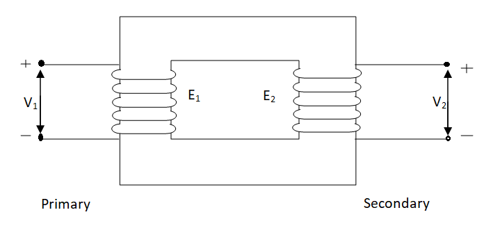
An ideal transformer has no losses i.e. its winding have no magnetic leakage and no ohmic resistance. Hence, an ideal transformer has only two purely inductive coils wound on a loss-free core.
Fig . Ideal Transformer
For above transformer when secondary is open and primary is having input sinusoidal voltage V1. An alternating current flows due to difference in potential. As primary coil is purely inductive so, Iµ current is drawn through it. This current is very small and logs V1 by 900.
The current Iµ produces magnetic flux φ and hence are in same phase. The flux is linked with both the windings and hence, self induced emf is produced E1 which is equal and opposite of V1. Similarly E2 is induced in secondary which is mutually induced emf E2 is proportional to rate of change of flux and number of secondary windings.
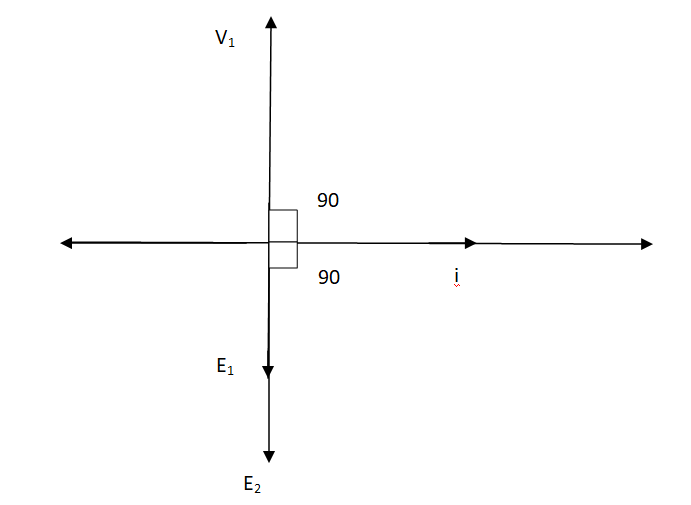
The phasor is shown below.
Phasor for Ideal Transformer
Emf Equation of Transformer :
N1 = No of primary turns
N2 = No of secondary turns
Φm = max flux in cone (wb)
Φm = Bm x A
f = Frequency of input(ac) Hz
Average rate of change of flux
= Φm / ¼
= 4 ΦmF volts
Average emf per turn = 4F ΦmV
As Φ varies sinusoidally rms value of induced emf is given as
Form factor = r.m.s value / average value = 1.11
r.m.s value of emf/turn = 1.11 x 4f Φm
= 4.44 f Φm volt
r.m.s value of induced emf in primary winding
= (induced emf/turn) x No of primary turns
E1 = 4.44 fN1Φm
E1 = 4.44 fN1BmA
r.m.s emf induced in secondary
E2 = 4.44 fN2Φm
E2 = 4.44 fN2BmA
E1/E2 = N1/N2 = K
K – voltage transformation
(i). If N2> N1i.e K > 1 STEP UP TRASFORMER
(II). If N1> N2i.e K<1 STEP DOWN TRASFORMER
FOR Ideal Transformer
V1 I1 = V2 I2 = 1/K
Hence, current is inversely proportional to the voltage transformation ratio.
Transformer Equivalent Circuit :
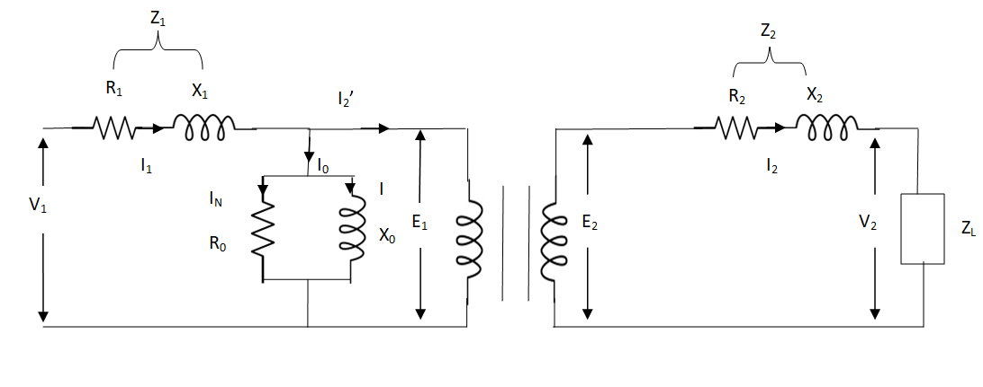
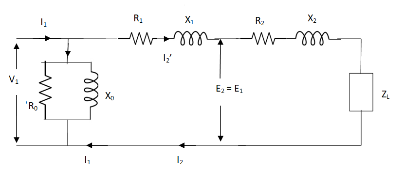
The basic transformer and its equivalent circuit both are shown below,
Fig. Equivalent Transformer Circuit
Iµ - magnetising component of current
Iw = working component
R0 – Non- inductive resistance
I0 – No load current
X0 = E1/I0. R0 = E1/Iw
E2/E1 = N2/N1 = K
E’2 = E2/K = E1
V’2 = V2/K
I’2 = K I2
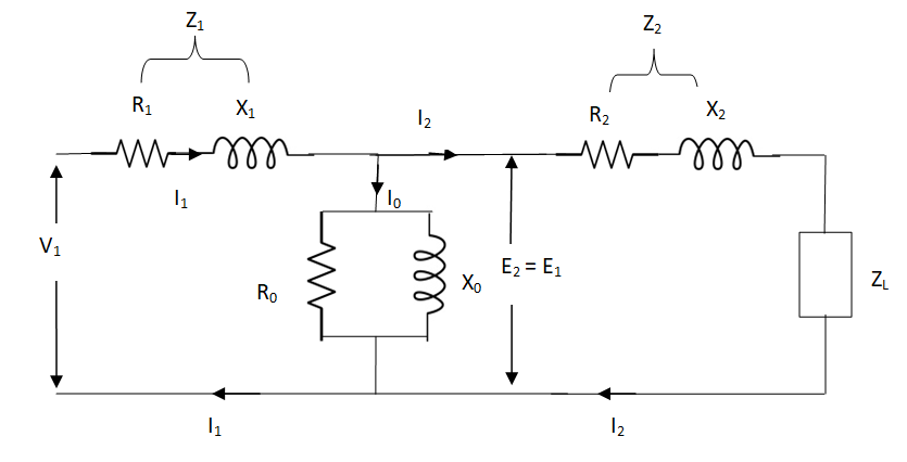
The total equivalent circuit is again given as,
But the above circuit is exact equivalent but harder to solve so, it can be further simplified as,
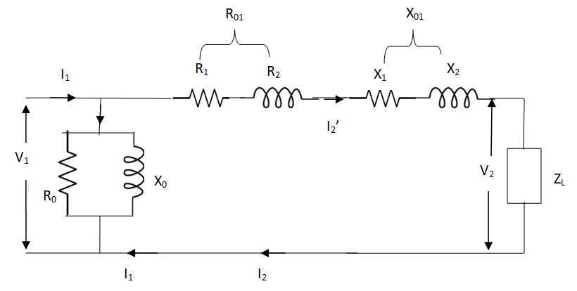
Z = Z1 + Zm || ( Z’2 + Z’L )
= Z1 + Zm(Z’2 + Z’L)/Zm + (Z’2 + Z’L)
Z’2 = R’2 + jX’2
Zm = impedance of exciting circuit
V1 = I1[ Z1 + Zm(Z’2 + Z’L) / Zm + (Z’2 + Z’L) ]
Core or Iron Loss :
This includes both hysteresis loss and eddy current loss. Iron or core loss is found from open circuit test.
Hysteresis Loss(Wh) = nB1.6max f V Watt
Eddy current Loss(We) = P B2max f2 t2 Watt
(2). Copper Loss :
This is due to ohmic resistance of the transformer windings.
Total cu loss = I21 R1 + I22 R2
= I21 R01 + I22 R02
Cu loss α I2
The value of cu loss is found from short-circuit test.
Voltage Regulation:
It can be explained in terms of various parameter of transformer.
(1). When transformer has constant primary voltage.
In this case secondary voltage decreases
0V2 = No-load secondary terminal voltage
0V2 = E2 = EK1 = KV1
V2 = secondary voltage on full-load.
Voltage Regulations is change in secondary terminal voltage from no-load to full load per unit full load voltage.
% regn down = 0V2 – V2/0V2 x 100
% regn up = 0V2 – V2/V2 x 100
(2). Voltage regulation in terms of primary values.
The secondary no-load terminal voltage as referred to primary is E’2 = E2/K = E1 = V1
For secondary full load voltage referred to primary is V’2 = V2/K
% regn = V1 – V’2/V1 x 100
% regn = I1 R01 cosφ + I1 X01 sinφ / V1 x 100
(3). As the transformer is loaded, to maintain a constant output voltage, the primary voltage should be increased. Here the regulation is given as
% regn = V’1 – V1 / V1 x 100
It can also be defined as the change in primary voltage from no-load to full-load at given power factor to maintain a constant output per unit primary voltage.
Q. A – 100 KVA transformer has 500 turns on primary and 80 turns on secondary. The primary and secondary resistances are 0.3 and 0.01 Ω respectively and the corresponding leakage reactances are 1.1 and 0.035 Ω. The supply voltage is 2400 V. Find
(i). Equivalent impedance referred to primary
(ii). Voltage regulation and the secondary terminal voltage for full load having pf 0.8 lagging?
Sol. Equivalent impedance referred to primary
Z01 = √R201 + X201 = R01 + jX01
R01 = R1 + R2/K2 = 0.3 + 0.01/K2 = 0.69 Ω
K = 80/500 = 4/25
X01 = X1 + X2/K2 = 1.1 + 0.035/(0.16)2 = 2.467 Ω
Z01 = 0.69 + j2.46
(ii). Secondary terminal voltage Z02 = K2 Z01
Z02 = 0.018 + j 0.063
= 0.065 ( 74.050
No-load secondary voltage = KV1
= 0.16 x 2400 = 384 V
I2 = 100 x 103/384 = 260.42 A
Full load voltage drop referred to secondary
= I2 (R02 cosφ– X02 Sinφ)
Cosφ = 0.8
Φ = 36.860
Sinφ = 0.6
= 260.42(0.018 x 0.8 – 0.063 x 0.6)
= - 6.094 V
% regn = -6.094/384 x 100
= -1.587
Secondary terminal voltage on-load
= 384 – (-6.094)
= 390.09 V
Efficiency:
Basically, efficiency is defined as
n = output/input
But for transformer there are small amount of losses so the improved way to find efficiency is
n = output/output + losses
n = output/output + cu loss + iron loss
Or n = Input – losses/Input
= 1 – Losses/Input
Condition for maximum efficiency :
For n to be maximum dn/dI1 = 0
(Ww) cu loss = I21 R01 or I22 R02
Iron loss = Hysteresis loss + Eddy current loss
= Wn + We = Wi
n = Input – losses/Input
Primary Input = V1I1 Cosφ1
n = V1 I1 Cosφ1 – losses/V1 I1 cos φ1
n = V1 I1 cos φ1 – I21 R01 – Wi / V1I1 cosφ1
= 1 – I1R01/V1cosφ1 – Wi/V1I1cosφ1
Differentiating w.r.t I1 both sides of above equation we have
Dn/dI1 = 0 – R01/V1cosφ1 + Wi/V1I21 Cosφ1
For max value dn/dI1 = 0
R01/V1cosφ1 = Wi/V1I21 cosφ1
Wi = I21 = I21 R01
Hence,
Wi = Wcu
Iron loss = copper loss
The value of output current for maximum efficiency will be
I2 = √Wi/R02
The maximum efficiency can also be given as,
nmax = full load x √ Iron loss / F.L .cu loss
Or
nmax = R’ x full load KVA x pf / R’ x full load KVA x pf + Wi + Wcu x 100
R’ = ratio of actual to full load KVA
Wi = iron loss (KW)
Wcu = copper loss (KW)
Q1). In a 50 KVA, 2200/200 V, 1-φ transformer, the iron and full-load copper losses are 400 W and 450 W respectively. Calculate n at unity power factor on (i). Full load (ii). Half-full load?
Sol. (i). Total loss = 400 + 450 = 850 W
F.L output at unity power factor = 50 x 1
= 50 KVA
n = 50 / 50 + .850 = 50/50.850 = 0.98 = 98%
(ii). Half full load, unity pf
= 50 KVA/2 = 25 KVA
Cu loss = 400 x (1/2)2 = 100 W
Iron loss is same = 450 W
Total loss = 100 + 450 = 550 W
n = 25/25 + 0.55 = 25/25.55 = 0.978 = 97.8 %
Q>. A 40 KVA 440/220 V, 1- φ, 50 Hz transformer has iron loss of 300 W. The cu loss is found to be 100 W when delivering half full-load current. Determine (i) n when delivering full load current at 0.8 lagging pf (ii) the percentage of full-load when the efficiency will be max.
Sol. Full load efficiency at 0.8 pf
= 40 x 0.8/(40 x 0.8) + losses
Full load cu loss = (440/220)2 x 100
= 400 W
Iron loss = 400 + 300
= 700 W
n = 40 x 0.8/(40 x 0.8) + 0.7 = 97.8 %
(ii). KVA for maximum / F.L KVA = √ iron loss / F.L cu loss
= √300/400 = 0.866
Reference
1 D.P Kothari and I.J Nagrath “Basic electrical engineering” Tata Mcgraw Hill,2010
2 D.C.Kulshtreshtha Basic electrical engineering” Tata Mcgraw Hill,2009
3 E.Hughes “Electrical and Electronics Technology” Pearson,2010
4 V.D.Toro “Electrical Engineering Fundamentals” Prentice Hall India, 1989