UNIT 1
Fundamentals of Computer
A computer system is basically a machine that simplifies complicated tasks. It should maximize performance and reduce costs as well as power consumption. The different components in the Computer System Architecture are Input Unit, Output Unit, Storage Unit, Arithmetic Logic Unit, Control Unit etc.
A diagram that shows the flow of data between these units is as follows −
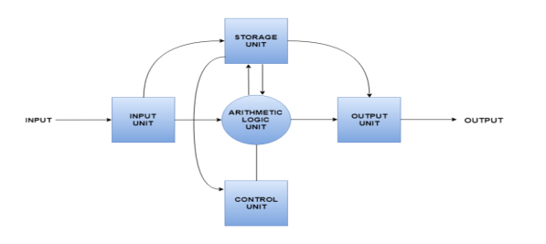
The input data travels from input unit to ALU. Similarly, the computed data travels from ALU to output unit. The data constantly moves from storage unit to ALU and back again. This is because stored data is computed on before being stored again. The control unit controls all the other units as well as their data.
Details about all the computer units are −
- Input Unit
The input unit provides data to the computer system from the outside. So, basically it links the external environment with the computer. It takes data from the input devices, converts it into machine language and then loads it into the computer system. Keyboard, mouse etc. are the most commonly used input devices.
- Output Unit
The output unit provides the results of computer process to the users i.e it links the computer with the external environment. Most of the output data is the form of audio or video. The different output devices are monitors, printers, speakers, headphones etc.
- Storage Unit
Storage unit contains many computer components that are used to store data. It is traditionally divided into primary storage and secondary storage. Primary storage is also known as the main memory and is the memory directly accessible by the CPU. Secondary or external storage is not directly accessible by the CPU. The data from secondary storage needs to be brought into the primary storage before the CPU can use it. Secondary storage contains a large amount of data permanently.
- Arithmetic Logic Unit
All the calculations related to the computer system are performed by the arithmetic logic unit. It can perform operations like addition, subtraction, multiplication, division etc. The control unit transfers data from storage unit to arithmetic logic unit when calculations need to be performed. The arithmetic logic unit and the control unit together form the central processing unit.
- Control Unit
This unit controls all the other units of the computer system and so is known as its central nervous system. It transfers data throughout the computer as required including from storage unit to central processing unit and vice versa. The control unit also dictates how the memory, input output devices, arithmetic logic unit etc. should behave.
The computer memory holds the data and instructions needed to process raw data and produce output. The computer memory is divided into large number of small parts known as cells. Each cell has a unique address which varies from 0 to memory size minus one.
Computer memory is of two types: Volatile (RAM) and Non-volatile (ROM). The secondary memory (hard disk) is referred as storage not memory.
But, if we categorize memory on behalf of space or location, it is of four types:
- Register memory
- Cache memory
- Primary memory
- Secondary memory
Register Memory
Register memory is the smallest and fastest memory in a computer. It is not a part of the main memory and is located in the CPU in the form of registers, which are the smallest data holding elements. A register temporarily holds frequently used data, instructions, and memory address that are to be used by CPU. They hold instructions that are currently processed by the CPU. All data is required to pass through registers before it can be processed. So, they are used by CPU to process the data entered by the users.
Registers hold a small amount of data around 32 bits to 64 bits. The speed of a CPU depends on the number and size (no. Of bits) of registers that are built into the CPU. Registers can be of different types based on their uses. Some of the widely used Registers include Accumulator or AC, Data Register or DR, the Address Register or AR, Program Counter (PC), I/O Address Register, and more.
Types and Functions of Computer Registers:
- Data Register: It is a 16-bit register, which is used to store operands (variables) to be operated by the processor. It temporarily stores data, which is being transmitted to or received from a peripheral device.
- Program Counter (PC): It holds the address of the memory location of the next instruction, which is to be fetched after the current instruction is completed. So, it is used to maintain the path of execution of the different programs and thus executes the programs one by one, when the previous instruction gets completed.
- Instructor Register: It is a 16-bit register. It stores the instruction which is fetched from the main memory. So, it is used to hold instruction codes, which are to be executed. The Control Unit takes instruction from Instructor Register, then decodes and executes it.
- Accumulator Register: It is a 16-bit register, which is used to store the results produced by the system. For example, the results generated by CPU after the processing are stored in the AC register.
- Address Register: It is a 12-bit register that stores the address of a memory location where instructions or data is stored in the memory.
- I/O Address Register: Its job is to specify the address of a particular I/O device.
- I/O Buffer Register: Its job is to exchange the data between an I/O module and the CPU.
Cache Memory
Cache memory is a high-speed memory, which is small in size but faster than the main memory (RAM). The CPU can access it more quickly than the primary memory. So, it is used to synchronize with high-speed CPU and to improve its performance.
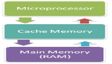
Cache memory can only be accessed by CPU. It can be a reserved part of the main memory or a storage device outside the CPU. It holds the data and programs which are frequently used by the CPU. So, it makes sure that the data is instantly available for CPU whenever the CPU needs this data. In other words, if the CPU finds the required data or instructions in the cache memory, it doesn't need to access the primary memory (RAM). Thus, by acting as a buffer between RAM and CPU, it speeds up the system performance.
Types of Cache Memory:
L1: It is the first level of cache memory, which is called Level 1 cache or L1 cache. In this type of cache memory, a small amount of memory is present inside the CPU itself. If a CPU has four cores (quad core cpu), then each core will have its own level 1 cache. As this memory is present in the CPU, it can work at the same speed as of the CPU. The size of this memory ranges from 2KB to 64 KB. The L1 cache further has two types of caches: Instruction cache, which stores instructions required by the CPU, and the data cache that stores the data required by the CPU.
L2: This cache is known as Level 2 cache or L2 cache. This level 2 cache may be inside the CPU or outside the CPU. All the cores of a CPU can have their own separate level 2 cache, or they can share one L2 cache among themselves. In case it is outside the CPU, it is connected with the CPU with a very high-speed bus. The memory size of this cache is in the range of 256 KB to the 512 KB. In terms of speed, they are slower than the L1 cache.
L3: It is known as Level 3 cache or L3 cache. This cache is not present in all the processors; some high-end processors may have this type of cache. This cache is used to enhance the performance of Level 1 and Level 2 cache. It is located outside the CPU and is shared by all the cores of a CPU. Its memory size ranges from 1 MB to 8 MB. Although it is slower than L1 and L2 cache, it is faster than Random Access Memory (RAM).
How does cache memory work with CPU?
When CPU needs the data, first of all, it looks inside the L1 cache. If it does not find anything in L1, it looks inside the L2 cache. If again, it does not find the data in L2 cache, it looks into the L3 cache. If data is found in the cache memory, then it is known as a cache hit. On the contrary, if data is not found inside the cache, it is called a cache miss.
If data is not available in any of the cache memories, it looks inside the Random Access Memory (RAM). If RAM also does not have the data, then it will get that data from the Hard Disk Drive.
So, when a computer is started for the first time, or an application is opened for the first time, data is not available in cache memory or in RAM. In this case, the CPU gets the data directly from the hard disk drive. Thereafter, when you start your computer or open an application, CPU can get that data from cache memory or RAM.
Primary Memory
Primary Memory is of two types: RAM and ROM.
RAM (Volatile Memory)
It is a volatile memory. It means it does not store data or instructions permanently. When you switch on the computer the data and instructions from the hard disk are stored in RAM.
CPU utilizes this data to perform the required tasks. As soon as you shut down the computer the RAM loses all the data.
ROM (Non-volatile Memory)
It is a non-volatile memory. It means it does not lose its data or programs that are written on it at the time of manufacture. So it is a permanent memory that contains all important data and instructions needed to perform important tasks like the boot process.
Secondary Memory
The secondary storage devices which are built into the computer or connected to the computer are known as a secondary memory of the computer. It is also known as external memory or auxiliary storage.
The secondary memory is accessed indirectly via input/output operations. It is non-volatile, so permanently stores the data even when the computer is turned off or until this data is overwritten or deleted. The CPU can't directly access the secondary memory. First, the secondary memory data is transferred to primary memory then the CPU can access it.
Some of the secondary memory or storage devices are described below:
1) Hard Disk:
It is a rigid magnetic disc that is used to store data. It permanently stores data and is located within a drive unit.
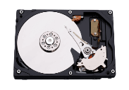
The hard disk is also known as a hard drive. It is a rigid magnetic disc that stores data permanently, as it is a non-volatile storage device. The hard disk is located within a drive unit on the computer's motherboard and comprises one or more platters packed in an air-sealed casing. The data is written on the platters by moving a magnetic head over the platters as they spin. The data stored on a computer's hard drive generally includes the operating system, installed software, and the user's files and programs, including pictures, music, videos, text documents, etc.
Components of Hard Drive:
The main components of a hard drive include a head actuator, read/write actuator arm, read/write head, platter, and spindle. A circuit board, which is called the disk controller or interface board, is present on the back of a hard drive. It allows the hard drive to communicate with the computer.
2) Solid-state Drive:
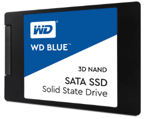
SSD (Solid State Drive) is also a non-volatile storage medium that is used to hold and access data. Unlike a hard drive, it does not have moving components, so it offers many advantages over SSD, such as faster access time, noiseless operation, less power consumption, and more.
As the cost of SSD has come down, it has become an ideal replacement for a standard hard drive in desktop and laptop computers. It is also suitable for notebooks, and tablets that don't require lots of storage.
3) Pen drive:

Pen drive is a compact secondary storage device. It is also known as a USB flash drive, thumb drive or a jump drive. It connects to a computer via a USB port. It is commonly used to store and transfer data between computers. For example, you can write a report using a computer and then copy or transfer it in the pen drive. Later, you can connect this pen drive to a computer to see or edit your report. You can also store your important documents and pictures, music, videos in the pen drive and keep it at a safe place.
Pen drive does not have movable parts; it comprises an integrated circuit memory chip that stores the data. This chip is housed inside a plastic or aluminium casing. The data storage capacity of the pen drive generally ranges from 2 GB to 128 GB. Furthermore, it is a plug and play device as you don't need additional drives, software, or hardware to use it.
4) SD Card:
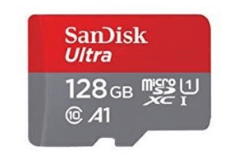
SD Card stands for Secure Digital Card. It is most often used in portable and mobile devices such as smartphones and digital cameras. You can remove it from your device and see the things stored in it using a computer with a card reader.
There are many memory chips inside the SD card that store the data; it does not have moving parts. SD cards are not created equal, so they may differ from each other in terms of speed, physical sizes, and capacity. For example, standard SD cards, mini SD cards, and micro SD cards.
5) Compact Disk (CD):
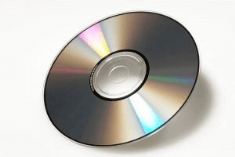
Compact Disk is a portable secondary storage device in the shape of a round medium disk. It is made of polycarbonate plastic. The concept of CD was co-developed by Philips and Sony in 1982. The first CD was created on 17 August 1982 at the workshop of Philips in Germany.
In the beginning, it was used for storing and playing sound recordings, later it was used for various purposes such as for storing documents, audio files, videos, and other data like software programs in a CD.
Physical characteristics of a CD/ Structure of CD:
A standard CD is around 5 inches in diameter and 0.05 inches in thickness. It is made of a clear polycarbonate plastic substrate, a reflective metallic layer, and a clear coating of acrylic plastic. These thin circular layers are attached one on top of another as described below:
- A polycarbonate disc layer at the bottom has the data encoded by creating lands and pits.
- The polycarbonate disc layer is coated with a thin aluminium layer that reflects the laser.
- The reflective aluminium layer is coated with a lacquer layer to prevent oxidation in order to protect the below layers. It is generally spin coated directly on the top of the reflective layer.
- The label print is applied on the lacquer layer, or artwork is screen printed on the top of the disc on the lacquer layer by offset printing or screen printing.
How Does a CD Work?
The data or information is stored or recorded or encoded in CD digitally using a laser beam that etches tiny indentations or bumps on its surface. The bump is called a pit, which represents the number 0. Space, where the bump is not created, is called land, and it represents the number 1. Thus, the data is encoded into a compact disc by creating pits (0) and lands (1). The CD players use laser technology to read the optically recorded data.
6) DVD:
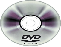
DVD is short for digital versatile disc or digital video disc. It is a type of optical media used for storing optical data. Although it has the same size as a CD, its storage capacity is much more than a CD. So, it is widely used for storing and viewing movies and to distribute software programs as they are too large to fit on a CD. DVD was co-developed by Sony, Panasonic, Philips, and Toshiba in 1995.
Types of DVDs:
DVDs can be divided into three main categories which are as follows:
- DVD-ROM (Read-Only): These types of DVDs come with media already recorded on them, such as movie dvds. As the name suggests, data on these discs cannot be erased or added, so these discs are known as a read-only or non-writable DVD.
- DVD-R (Writable): It allows you to record or write information to the DVD. However, you can write information only once as it becomes a read-only DVD once it is full.
- DVD-RW (Rewritable or Erasable): This type of discs can be erased, written, or recorded multiple times.
These are 4 types of memory access methods:
1. Sequential Access:-
In this method, the memory is accessed in a specific linear sequential manner, like accessing in a single Linked List. The access time depends on the location of the data.
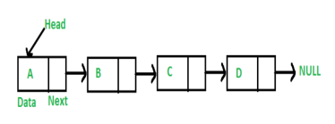
Applications of this sequential memory access are magnetic tapes, magnetic disk and optical memories.
2. Random Access:-
In this method, any location of the memory can be accessed randomly like accessing in Array. Physical locations are independent in this access method.
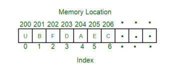
Applications of this random memory access are RAM and ROM.
3. Direct Access:-
In this method, the particular location of the memory can be accessed directly like accessing in Array. This method is a combination of above two access methods. The access time depends on both the memory organization and characteristics of storage technology. The access is semi-random or direct.
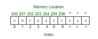
Application of thus direct memory access ismagnetic hard disk, read/write header.
4. Associate Access:-
In this memory, a word is accessed rather than its address. This access method is a special type of random access method.
What is a programming language?
A programming language defines a set of instructions that are compiled together to perform a specific task by the CPU (Central Processing Unit). The programming language mainly refers to high-level languages such as C, C++, Pascal, Ada, COBOL, etc.
Each programming language contains a unique set of keywords and syntax, which are used to create a set of instructions. Thousands of programming languages have been developed till now, but each language has its specific purpose. These languages vary in the level of abstraction they provide from the hardware. Some programming languages provide less or no abstraction while some provide higher abstraction. Based on the levels of abstraction, they can be classified into two categories:
- Low-level language
- High-level language
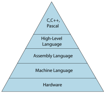
The image which is given below describes the abstraction level from hardware. As we can observe from the below image that the machine language provides no abstraction, assembly language provides less abstraction whereas high-level language provides a higher level of abstraction.
Low-level language
The low-level language is a programming language that provides no abstraction from the hardware, and it is represented in 0 or 1 forms, which are the machine instructions. The languages that come under this category are the Machine level language and Assembly language.
Machine-level language
The machine-level language is a language that consists of a set of instructions that are in the binary form 0 or 1. As we know that computers can understand only machine instructions, which are in binary digits, i.e., 0 and 1, so the instructions given to the computer can be only in binary codes. Creating a program in a machine-level language is a very difficult task as it is not easy for the programmers to write the program in machine instructions. It is error-prone as it is not easy to understand, and its maintenance is also very high. A machine-level language is not portable as each computer has its machine instructions, so if we write a program in one computer will no longer be valid in another computer.
The different processor architectures use different machine codes, for example, a PowerPC processor contains RISC architecture, which requires different code than intel x86 processor, which has a CISC architecture.
Assembly Language
The assembly language contains some human-readable commands such as mov, add, sub, etc. The problems which we were facing in machine-level language are reduced to some extent by using an extended form of machine-level language known as assembly language. Since assembly language instructions are written in English words like mov, add, sub, so it is easier to write and understand.
As we know that computers can only understand the machine-level instructions, so we require a translator that converts the assembly code into machine code. The translator used for translating the code is known as an assembler.
The assembly language code is not portable because the data is stored in computer registers, and the computer has to know the different sets of registers.
The assembly code is not faster than machine code because the assembly language comes above the machine language in the hierarchy, so it means that assembly language has some abstraction from the hardware while machine language has zero abstraction.
Differences between Machine-Level language and Assembly language
The following are the differences between machine-level language and assembly language:
Machine-level language | Assembly language |
The machine-level language comes at the lowest level in the hierarchy, so it has zero abstraction level from the hardware. | The assembly language comes above the machine language means that it has less abstraction level from the hardware. |
It cannot be easily understood by humans. | It is easy to read, write, and maintain. |
The machine-level language is written in binary digits, i.e., 0 and 1. | The assembly language is written in simple English language, so it is easily understandable by the users. |
It does not require any translator as the machine code is directly executed by the computer. | In assembly language, the assembler is used to convert the assembly code into machine code. |
It is a first-generation programming language. | It is a second-generation programming language. |
High-Level Language
The high-level language is a programming language that allows a programmer to write the programs which are independent of a particular type of computer. The high-level languages are considered as high-level because they are closer to human languages than machine-level languages.
When writing a program in a high-level language, then the whole attention needs to be paid to the logic of the problem.
A compiler is required to translate a high-level language into a low-level language.
Advantages of a high-level language
- The high-level language is easy to read, write, and maintain as it is written in English like words.
- The high-level languages are designed to overcome the limitation of low-level language, i.e., portability. The high-level language is portable; i.e., these languages are machine-independent.
Differences between Low-Level language and High-Level language
The following are the differences between low-level language and high-level language:
Low-level language | High-level language |
It is a machine-friendly language, i.e., the computer understands the machine language, which is represented in 0 or 1. | It is a user-friendly language as this language is written in simple English words, which can be easily understood by humans. |
The low-level language takes more time to execute. | It executes at a faster pace. |
It requires the assembler to convert the assembly code into machine code. | It requires the compiler to convert the high-level language instructions into machine code. |
The machine code cannot run on all machines, so it is not a portable language. | The high-level code can run all the platforms, so it is a portable language. |
It is memory efficient. | It is less memory efficient. |
Debugging and maintenance are not easier in a low-level language. | Debugging and maintenance are easier in a high-level language. |
A flowchart is a schematic representation of an algorithm or a stepwise process, showing the steps as boxes of various kinds, and their order by connecting these with arrows. Flowcharts are used in designing or documenting a process or program.
ALGORITHM
Algorithm
· Set of step-by-step instructions that perform a specific task or operation
· ―Natural‖ language NOT programming language
Pseudocode
· Set of instructions that mimic programming language instructions
Flowchart
· Visual program design tool
· ―Semantic‖ symbols describe operations to be performed
FLOWCHARTS
Definitions:
A flowchart is a schematic representation of an algorithm or a stepwise process, showing the steps as boxes of various kinds, and their order by connecting these with arrows. Flowcharts are used in designing or documenting a process or program.
A flow chart, or flow diagram, is a graphical representation of a process or system that details the sequencing of steps required to create output.
A flowchart is a picture of the separate steps of a process in sequential order.
TYPES:
High-Level Flowchart
A high-level (also called first-level or top-down) flowchart shows the major steps in a process. It illustrates a "birds-eye view" of a process, such as the example in the figure entitled High-Level Flowchart of Prenatal Care. It can also include the intermediate outputs of each step (the product or service produced), and the sub-steps involved. Such a flowchart offers a basic picture of the process and identifies the changes taking place within the process. It is significantly useful for identifying appropriate team members (those who are involved in the process) and for developing indicators for monitoring the process because of its focus on intermediate outputs.
Most processes can be adequately portrayed in four or five boxes that represent the major steps or activities of the process. In fact, it is a good idea to use only a few boxes, because doing so forces one to consider the most important steps. Other steps are usually sub-steps of the more important ones.
Detailed Flowchart
The detailed flowchart provides a detailed picture of a process by mapping all of the steps and activities that occur in the process. This type of flowchart indicates the steps or activities of a process and includes such things as decision points, waiting periods, tasks that frequently must be redone (rework), and feedback loops. This type of flowchart is useful for examining areas of the process in detail and for looking for problems or areas of inefficiency. For example, the Detailed Flowchart of Patient Registration reveals the delays that result when the record clerk and clinical officer are not available to assist clients.
Deployment or Matrix Flowchart
A deployment flowchart maps out the process in terms of who is doing the steps. It is in the form of a matrix, showing the various participants and the flow of steps among these participants. It is chiefly useful in identifying who is providing inputs or services to whom, as well as areas where different people may be needlessly doing the same task. See the Deployment of Matrix Flowchart.
ADVANTAGES OF USING FLOWCHARTS
The benefits of flowcharts are as follows:
1. Communication: Flowcharts are better way of communicating the logic of a system to allconcerned.
2. Effective analysis: With the help of flowchart, problem can be analysed in more effective way.
Proper documentation: Program flowcharts serve as a good program documentation, which isneeded for various purposes.
4. Efficient Coding: The flowcharts act as a guide or blueprint during the systems analysis andprogram development phase.
5. Proper Debugging: The flowchart helps in debugging process.
6. Efficient Program Maintenance: The maintenance of operating program becomes easy withthe help of flowchart. It helps the programmer to put efforts more efficiently on that part
Advantages:
· Logic Flowcharts are easy to understand. They provide a graphical representation of actions to be taken.
· Logic Flowcharts are well suited for representing logic where there is intermingling among many actions.
Disadvantages:
· Logic Flowcharts may encourage the use of GoTo statements leading software design that is unstructured with logic that is difficult to decipher.
· Without an automated tool, it is time-consuming to maintain Logic Flowcharts.
· Logic Flowcharts may be used during detailed logic design to specify a module.
· However, the presence of decision boxes may encourage the use of GoTo statements, resulting in software that is not structured. For this reason, Logic Flowcharts may be better used during Structural Design
LIMITATIONS OF USING FLOWCHARTS
1. Complex logic: Sometimes, the program logic is quite complicated. In that case, flowchartbecomes complex and clumsy.
2. Alterations and Modifications: If alterations are required the flowchart may require re-drawing completely.
3. Reproduction: As the flowchart symbols cannot be typed, reproduction of flowchart becomes aproblem.
4. The essentials of what is done can easily be lost in the technical details of how it is done.
GUIDELINES FOR DRAWING A FLOWCHART
Flowcharts are usually drawn using some standard symbols; however, some special symbols can also be developed when required. Some standard symbols, which are frequently required for flowcharting many computer programs.
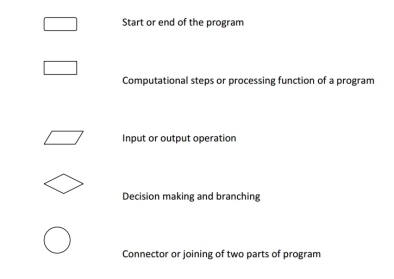
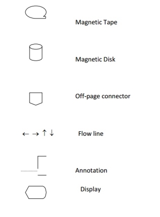
The following are some guidelines in flowcharting:
(a) In drawing a proper flowchart, all necessary requirements should be listed out in logical order.
(b) The flowchart should be clear, neat and easy to follow. There should not be any room for ambiguity in understanding the flowchart.
(c) The usual direction of the flow of a procedure or system is from left to right or top to bottom.
(d) Only one flow line should come out from a process symbol.

(e) Only one flow line should enter a decision symbol, but two or three flow lines, one for each possible answer, should leave the decision symbol.
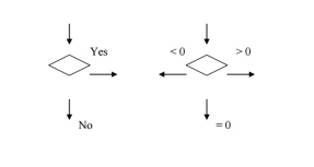
(f) Only one flow line is used in conjunction with terminal symbol.

(g) Write within standard symbols briefly. As necessary, you can use the annotation symbol to describe data or computational steps more clearly.

(h) If the flowchart becomes complex, it is better to use connector symbols to reduce the number of flow lines. Avoid the intersection of flow lines if you want to make it more effective and better way of communication.
(i) Ensure that the flowchart has a logical start and finish.
(j) It is useful to test the validity of the flowchart by passing through it with a simple test data.
Examples
Sample flowchart
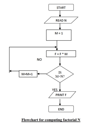
A flowchart for computing factorial N (N!) Where N! = 1 * 2 * 3 *...* N. This flowchart represents a "loop and a half" — a situation discussed in introductory programming textbooks that requires either a duplication of a component (to be both inside and outside the loop) or the component to be put inside a branch in the loop.
Sample Pseudocode
ALGORITHM Sample
GET Data
WHILE There Is Data
DO Math Operation
GET Data
END WHILE
END ALGORITHM
Text Books:
1. Satinder Bal Gupta & Amit Singla, Fundamental of Computers and Programming in C, Shree Mahavir Book (Publishers), New Delhi
2. Ajay Mittal, Programming in C, ‘A Practical Approach’, Pearson Education.
3. Byron Gottfried, Schaum's Outline of Programming with C, McGraw-Hill
4. E. Balaguruswamy, Programming in ANSI C, Tata McGraw-Hill
5. YashavantKanetkar, Let Us C, BPB Publication.