UNIT 2
Fundamental of Static
2.1(a) Introduction of Force
Scalar and Vectors:
All physical quantities in engineering mechanics are measured using either scalars or vectors.
Scalar: When a quantity is specified only by its magnitude, then it is known as scalar quantity. E.g. Length, mass, and time.
Vector: A quantity that requires magnitude as well as direction for its specification is known as a vector quantity. E.g. Force, moment and position. A vector is shown graphically by an arrow.
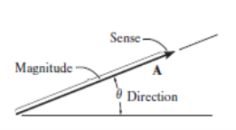
The above displayed figure represents the vector quantity.
Force system
Force [(F) or (P)] :-
It is an external agency which produces or tends to produce, destroy or tends to destroy motion.
OR
It is an external agent which changes or tends to change the state of motion of body.
It is a vector quantity.
Force is also known as rate of change of momentum.
As momentum = mass x velocity
But mass will never change, then
Force = mass x rate of change of velocity
= mass x Acceleration
F = P = ma
S.I. Unit: - Newton (N)
Kilo Newton (KN) = 103 N
Mega Newton (MN) = 106 N
Giga Newton (GN) = 103 N
Tera Newton (TN) = 1012 N
1 Kg Force:-
Force required producing unit gravitational acceleration on unit mass.
01 kg force = mass x Acceleration (gravity)
= 1 kg x 9.81 m / s2
= 9.81 kg.m / s2
1 kg.F = 9.81 Kg m / s2
1 kg.F = 9.81 N
i.e. 1 Kg = 9.81 N
Effects of a force:
It may produce the effects on body on which it is acted as:
1. Motion of the body may be changed.
2. It may retard the motion of a body.
3. It may reduce the acting forces to make it stop or be in equilibrium
4. It may even create internal stresses in the body.
Characteristics of a force:
Following are the characteristics of a force:
1. Magnitude of the force (i.e., 100 N, 50 N, 20 kN, 5 kN, etc.)
2. The direction of the line, along which the force acts.
3. Nature of the force. This is denoted by placing an arrow head on the line of action of the force.
4. The point at which (or through which) the force acts on the body.
2.1(c) Types of force:
Force is a physical cause that can change the state of motion or the dimensions of an object. There are two types of forces based on their applications:
- Contact Force
- Non-Contact Force
Contact Force

Forces that act on a body either directly or through a medium are called contact forces.
Examples of contact forces are:
- Muscular Force
- Mechanical Force
- Frictional Force
We can make use of the muscular force of animals like bullocks, horses, and camels to get the activities done. The frictional force is another type of contact force, which acts between a pair of a surface in contact and tends to oppose the motion of one surface over the other.
Non-Contact Force

Forces that act through spaces without making direct contact with the body are called non-contact forces.
Examples of non-contact forces are:
- Gravitational Force
- Electrostatic Force
- Magnetic Force
The force exerted by a magnet on other magnets is called magnetic force. Magnetic force and electrostatic force act on an object from a distance, that’s the reason they are non-contact forces. The strength of gravity is an attractive force that is exerted by the Earth on objects, which make them fall to the land. The weight of a body is the force that is pulled by the earth towards the centres.
2.1(d) Type of force systems
When a single agency is acting on body then it is known as force. But when no of forces are acting on the body simultaneously, then it is known “System of force”.
Types of Force System:-
1. Co-planer Forces
2. Non-Co-planer Forces
3. Co-linear Forces
4 Non Co-linear Forces
5. Concurrent Forces
6. Non Concurrent Forces
7. Parallel Forces (Like &unlike)
8. Coplanar Concurrent Forces
9. Coplanar Non Concurrent Forces
10. Non Coplanar Concurrent Forces
11. Non Coplanar Non Concurrent Forces
1. Co – planer Force System / Forces:-
The forces whose line of action lies on the same plane are called as Co-planer Forces.


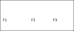
The forces which are acting in the same plane are known as co-planer forces.
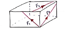
2. Non Co-planer Force System / Forces:-
- A forces whose line of action does not lie in the same plane ( i.e. lie in different planes )
- Forces which are acting in the different planes known as non-co-planer forces (system).
3. Co-linear force system / Forces:-
- The forces whose line of action lies on the same line are called as co-linear forces.
- The forces which are acting along the same straight line are called as co-linear forces.
4. Non – Collinear Forces / force system:-
- The forces which are not acting along the same straight line are known as non-co-linear forces.
- The forces whose line of action doesn’t lie on the same line.
F2


 F1
F1


 F1 F3 F2
5. Concurrent forces / Force system:-
- The forces whose line of action meets at one common point are called concurrent forces.
- The forces which are passing through a common point are concurrent forces.
- The forces which meet at one point are concurrent forces.
6. Non Concurrent force system / forces:-
- The forces which are not passing through common point OR
- The forces whose line of action does not meet at common point OR
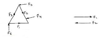 - The force which does not meet at one point are called as non-concurrent forces.
7. Parallel Forces / Force system:-
The forces whose line of actions is parallel to each other are called as parallel forces.
- Like parallel Forces :-
The forces whose line of actions is parallel to each other and having same direction are called like parallel forces.
Forces which are parallel to each other & acting in same direction are called as Like parallel forces.


F1 F2 F3
b. Unlike parallel Forces:-
The forces which are parallel to each other but having different directions or
The forces which are parallel to each other & acting in opposite direction are called as unlike parallel forces.


F1 F2 F3 F4 F5
8. Coplanar concurrent forces:-
The forces which meets at one point & their lines of action also lie on the same plane are called as coplanar concurrent force system.

 F5 F4
F5 F4


 F1
F1
F2 F3
9. Coplanar non concurrent forces:-
The forces which do not meet at one point but their line of action lies on the same plane are known as coplanar non-concurrent system of force.

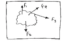
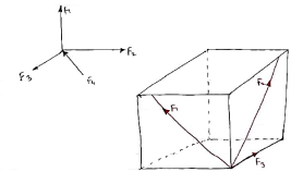
10. Non Coplanar concurrent forces:-
The forces which meets at one point but their line of action do not lie on the same plane are known as non-coplanar concurrent forces.
11. Non coplanar non-concurrent forces:-
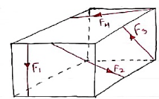 Their forces which do not meet at one point & their lines of actions do not lie on the same plane are called as non - coplanar non concurrent forces.
2.1(e) Principle of Transmissibility
The state of the rigid body will not change if force acting on a body is replaced by another force of same magnitude & direction acting anywhere on the body along the line of action of replaced force. The value of force will not change along the Line of action of force within the body.

2.1(f) Resultant of force systems
Resultant Force:
When many forces are acting, the overall effect can be considered in a single force. This single force is called resultant force and the given individual forces are called component forces.
Methods for the resultant force
Though there are many methods for finding out the resultant force of a number of given forces, yet the following are important from the subject point of view:
- Analytical method.
- Method of resolution.
Analytical method includes the Parallelogram law of Vectors which is described as “If two forces, acting simultaneously on a particle, be shown by two sides of parallelogram, then the resultant will be the diagonal between these sides of parallelogram.”
Mathematically, resultant force,

Where R is the resultant force, A and B are component vectors and  is the angle between the two vectors, as shown below.
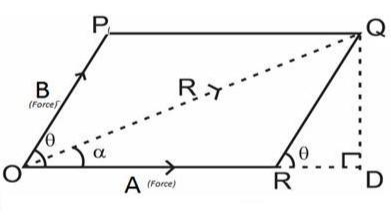
For finding the direction of resultant vector, we need to find the angle between A and R i.e.  .
.

Method of resolution for the resultant force:
1. Horizontal resolution of forces is done and sum is taken (i.e., ∑H).
2. Vertical resolution of forces is done and sum is taken (i.e., ∑V).
3. The resultant R of the given forces will be given by the equation:

4. When the resultant is being inclined by an angle of θ, with the horizontal, we have

Thus value of the angle θ will vary depending upon the values of ∑V and ∑H as discussed below:
1. When ∑V is +ve, the resultant makes an angle between 0° and 180°. But when ∑V is –ve, the resultant makes an angle between 180° and 360°.
2. When ∑H is +ve, the resultant makes an angle between 0° to 90° or 270° to 360°. But when ∑H is –ve, the resultant makes an angle between 90° to 270°.
2.1(h) Composition and Resolution of force system
Composition:-
The process of finding out the resultant force of a given force system.
Resolution:-
It is the procedure of splitting up a single force into number of components without changing the effect of same on the body.
Forces are generally resolved into two components along two mutually perpendicular directions.
Methods of composition / methods for the Resultant force.
 A]. Analytical Method B] Graphical Method
 Resultant of more than two Forces (concurrent & non-concurrent) Method of Resolution

2.1(i) Resolution method for coplanar concurrent force system:
There are many ways in which forces can be manipulated. It is often easier to work with a large, complicated system of forces by reducing it to an ever decreasing number of smaller problems. This is called the "resolution" of forces or force systems. This is one way to simplify what may otherwise seem to be an impossible system of forces acting on a body. Certain systems of forces are easier to resolve than others. Coplanar force systems have all the forces acting in in one plane. They may be concurrent, parallel, non-concurrent or non-parallel. All of these systems can be resolved by using graphic statics or algebra.
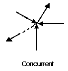
A concurrent coplanar force system is a system of two or more forces whose lines of action ALL intersect at a common point. However, all of the individual vectors might not acutally be in contact with the common point. These are the most simple force systems to resolve with any one of many graphical or algebraic options.
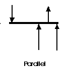
A parallel coplanar force system consists of two or more forces whose lines of action are ALL parallel. This is commonly the situation when simple beams are analyzed under gravity loads. These can be solved graphically, but are combined most easily using algebraic methods.
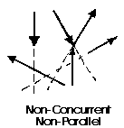
The last illustration is of a non-concurrent and non-parallel system. This consists of a number of vectors that do not meet at a single point and none of them are parallel. These systems are essentially a jumble of forces and take considerable care to resolve.
2.2(a) Moment of a force
Moment:-
The turning effect produced by a force on the body on which it acts is called as Moment.
Moment of force about any point is the product of magnitude of force and perpendicular distance of force from the point about which moment is to be taken.
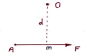
Let force F is applied at point A as shown & O is any point about which we want to take moment.
Thus from point O, draw OM line perpendicular to the line of action of force.
OM = d = Perpendicular distance between Force & point O.
Moment = M = F x d
Graphical representation of Moment:-
- Select suitable scale to locate the force graphically.
- Draw a line parallel to line of action of force. Length of this line can be calculated from selected scale.
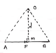 - Length of a line will be equal to magnitude of force.In the figure, Force F is represented by line AB.
- Now let O is the moment centre &
OM = d = perpendicular distance
By definition, Mo = F x d
Now join OA & OB, then
In Δ OAB
Area (ΔOAB) = ½ x AB x OM
2 (Area of ΔOAB) = F x d = Mo
Thus the moment of any force about any point is numerically equal to twice area of triangle in which base represents force & height represents the perpendicular distance.
2.2(b) Principle of moments
The principle that, when a system of coplanar forces acts on a body and produces a state of equilibrium, the sum of the moments of the forces about any point in the plane is zero.
Suppose, for example, that a light rod is supported by a pivot and that a particle of mass m 1 is suspended from the rod at a distance d 1 to the right of the pivot, and another of mass m 2 is suspended from the rod at a distance d 2 to the left of the pivot. The force due to gravity on the first particle has magnitude m 1 g, and its moment about the pivot is equal to (m 1 g).d 1 clockwise. Corresponding to the second particle, there is a moment (m 2 g).d 2 anticlockwise. By the principle of moments, there is equilibrium if (m 1 g).d 1=(m 2 g)d 2.
To use the vector definition of moment in this example, take the pivot as the origin O, the x-axis along the rod with the positive direction to the right and the y-axis vertical with the positive direction upwards. The force due to gravity on the first particle is −m 1 g j, and the moment of the force about O equals (d 1 i)×(−m 1 g j)=−(m 1 g)d 1 k. Corresponding to the second particle, the moment equals (−d 2 i)×(−m 2 g j)=(m 2 g)d 2 k. The principle of moments gives the same condition for equilibrium as before.
2.2(c) Parallel force system
Parallel Forces / Force system:-
The forces whose line of actions is parallel to each other are called as parallel forces.
- Like parallel Forces :-
The forces whose line of actions is parallel to each other and having same direction are called like parallel forces.
Forces which are parallel to each other & acting in same direction are called as Like parallel forces.


F1 F2 F3
b. Unlike parallel Forces:-
The forces which are parallel to each other but having different directions or
The forces which are parallel to each other & acting in opposite direction are called as unlike parallel forces.


F1 F2 F3 F4 F5
2.2(d) Couples
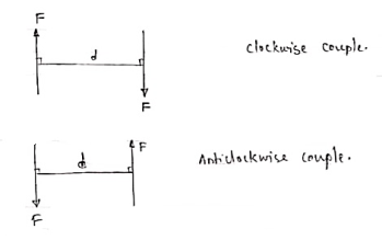
A pair of two equal and opposite (unlike) parallel forces (of same magnitude) is known as couple.
Properties of Couple:-
1. Two unlike parallel, non-collinear forces of same magnitude will form couple.
2. Resultant of couple is always zero.
3. Moment of couple is product of one of the force & lever arm of couple.
M = F xd
Lever arm of couple = ḻlar distance betn couple forces.
4. Couple cannot be balanced by single force.
5. Couple can be balanced only by another couple of opposite nature.
6. Moment of couple is independent of moment centre. i.e. Ref. Point is not required to take moment of couple.
A force of 15 N is applied at an angle of 600 to the edge of door as shown in figure. Find the moment of this force.
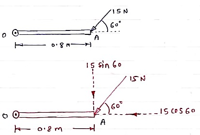
Solution:-
Resolving force at point B & then taking the moment about point O,
M0 = (15 Cos 60 x 0) + (15 Sin 60 x 0.8)
= 0 + 10.39
 M0 = 10.39 N.m
Question: A 90 N force is applied to the control rod AB. Determine moment of this Force about point B.
Solution: As we don’t know perpendicular distance between force & point ‘ B ’, Let us resolve the force into two components.
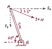 X – Component of force
Fx = 90 Cos 25 = 81.567 N
Y – Component of force
Fy = 90 Sin 25 = 38.036
Now taking moments about point B.
MB = [Fx x (3 Sin 65)] - [Fy x (3 Cos 65)]
MB = (81.65 x 2.72) – (38.036 x 1.27)
= 221.843 – 48.31
 MB = 173.53 N.m
2.2(e) Equivalent couples
Every set of forces and moments has an equivalent force couple system. This is a single force and pure moment (couple) acting at a single point that is statically equivalent to the original set of forces and moments.
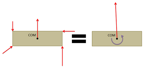
Any set of forces on a body can be replaced by a single force and a single couple acting that is statically equivalent to the original set of forces and moments. This set of an equivalent force and a couple is known as the equivalent force couple system.
To find the equivalent force couple system, you simply need to follow the steps below.
- First, choose a point to take the equivalent force couple system about. Any point will work, but the point you choose will affect the final values you find for the equivalent force couple system. Traditionally this point will either be the center of mass of the body or some connection point for the body.
- Next resolve all the forces not acting though that point to a force and a couple acting at the point you chose.
- To find the "force" part of the equivalent force couple system adds together all the force vectors. This will give you the magnitude and the direction of the force in the equivalent force couple system.
- To find the "couple" part of the equivalent force couple system, add together any moment vectors (this could be moments originally acting on the body or moments from the resolution of the forces into forces and couples). This will give you the magnitude and direction of the pure moment (couple) in the equivalent force couple system.
2.2(f) Operations with couples
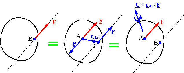
A single force applied to a rigid body creates a tendency for a linear motion and a rotational motion, with respect to an arbitrary point B.
Let’s shift its line of action so it passes through the point B. The tendency for creation of linear motion will not change. However, we will need a couple to maintain tendency for a rotational motion.
This can be done by adding two opposite and collinear forces with the line of action parallel to  and passing through B:

Note: All 3 systems are equivalent – they lead to the same result.
The combination of a force and a couple is called a force-couple system.
Force-Couple System, 3D
Similarly, force-couple can be computed for 3D body:

Where original force  applied at 𝑨 is equivalent to the force and a couple at point 𝑶.
Here  is a free vector (not attached to 𝑷) and
  is a position vector from 𝑶 to any point on a line of action of
  , i.e. not restricted to
  .
.
Applications of Force-Couple Systems
Force to force-couple equivalency is very important in statics, since it allows us to shift the line of action of a force and :
1) To analyze the effect of action of a force with respect to an arbitrary (critical) point of interest within a structure
2) To (sometimes) simplify calculations
3) To compute resultants of systems of forces at particular points
System of Forces-Couples
A system of forces-couples is equivalent to a force-couple system at an arbitrary point 𝑶, where resultant force  acting at 𝑶 is:

And a resultant couple  is the sum of all couples plus the sum of moments of the original forces about 𝑶:

Where the first additive in the last sum is a sum of all couples and the second one is a sum of all moments about 𝑶.
2.2(g) Equivalent system of forces
The basic idea: Two force systems are equivalent if they result in the same resultant force and the same resultant moment.

Moving a force along its line of action: Moving a force along its line of action results in a new force system which is equivalent to the original force system.
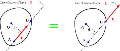
Moving a force off its line of action: If a force is moved off its line of action, a couple must be added to the force system so that the new system generates the same moment as the old system.
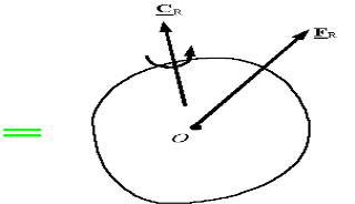
The resultant of a force and couple system: For any point O, every force and couple system can be made equivalent to a single force passing through O and a single couple. The single force passing through O is equal to the resultant force of the original system, and the couple is equal to the resultant moment of the original system around point O


When can one reduce a force and couple system to a single force?: For a force and couple system if the resultant force and the resultant couple are perpendicular, then one can find an equivalent system with a single force and no couple. To obtain this system, move the resultant force a distance d along the line perpendicular to the plane of the resultant force and resultant couple until the resultant force creates a moment equivalent to the resultant couple.


Note: All 2-D force systems can be reduced to a single force. To find the line of action of the force, the moment of the original system must be forced to be the same as the system with the single force.


2.3(a) Resultant of coplanar non-concurrent force system
The resultant of this force system is either a single force or a couple.
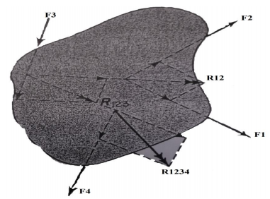
The resultant is a couple when the resultant of all but one of the forces of the system and the remaining force form a couple. To determine the resultant analytically, each force is resolved into rectangular components in the x and y directions.
1When the algebraic sum of the components in either the x or y direction, or both, is different from zero, the resultant is a force, and its magnitude can be determined from the following equations:
Rx=∑Fx
RY=∑FY
R=√ (RX2+RY2)
Tan-1Θx=RY/RX
The location of a point on the action line of the resultant is determined by the principle of moments.
𝑅𝑞 = ∑𝑀𝑂
Where q is the perpendicular distance from the moment axis through o to the resultant force R. The direction from O to R is determined from the sense of R and ∑ 𝑀𝑂
2. When the algebraic sum of the components of the forces is zero in two different directions, the resultant cannot be a single force but can be a couple in the plane of the forces. The magnitude of the moment of the couple and its sense of rotation can be determined as the algebraic sum of the moments of the forces of the system with respect to any point in the plane.
Note:- For the special case of a parallel coplanar force system with the x axis parallel to the forces R of the system y = 0 and the resultant if a force, is parallel to the x axis
2.3(b) Concentrated and distributed loads
Distributed Loads
Distributed loads may be replaced by concentrated loads acting through the balance/centre of the distribution or load area: THIS IS AN EQUIVALENT FORCE SYSTEM.
•w is the symbol used to describe the load per unit length.
•W is the symbol used to describe the total load.

Point load or concentrated load
Point load or concentrated load, as name suggest, acts at a point on the beam. If we will see practically, point load or concentrated load also distributed over a small area but we can consider such type of loading as point loading and hence such type of load could be considered as point load or concentrated load.
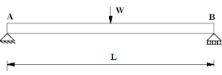
Following figure displayed here indicates the beam AB of length L which will be loaded with point load W at the midpoint of the beam. Load W will be considered here as the point load.
2.4(a) Equilibrium
Equilibrium
- A body is said to be in equilibrium if the resultant of all forces acting on it is zero.
- When the resultant of all the forces acting on the particle is zero, then, the particle is in equilibrium.
- If the resultant force acting on a particle is zero (or if particle is in equilibrium state) the, particle will remain at rest condition if it is originally at rest; or particle will move with constant speed in a straight line if it is originally in motion.
Condition for Equilibrium: R = 0 {  }
}
∑M = 0
 Equilibrium of body subjected to two forces:
P=Q, body is in equilibrium P=Q, but body is not in equilibrium
If an object is subjected to forces acting at two points, then body will be in equilibrium only when those two forces are equal & opposite.
2.4(b) Resultant &
Resultant Force:-
- If number of forces are acting simultaneously on a body, then it is possible to find out single force which could replace them, i.e. which would produce the same effect as produced by all given forces. This single force is called as Resultant force.
OR
- It is a single force which produces the same effect that is produced by number of forces when acting together.
Resultant is denoted by (R)
2.4(c) Equilibrant
Equilibrant:-
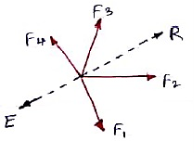 It is the single force which when acting with all other forces keeps the body at rest or in equilibrium.
It is denoted by (E).
2.4(d) Principle of action and reaction
Newton's third law states that whenever an object exerts a force on a second object, it exerts a force of equal magnitude and direction but in the opposite direction on the first. It is often stated as follows: Every action is always opposed by an equal but opposite reaction. In any interaction there are a pair of action and reaction forces located in the same direction with equal magnitude and opposite senses. The original formulation of Newton is:
With all action always occurs an equal and opposite reaction: it means that the mutual actions of two bodies are always the same and directed in the opposite direction.
This third law of Newton is completely original (since the first two had already been proposed in another way by Galileo, Hooke and Huygens) and makes the laws of mechanics a logical and complete set. It states that for each force acting on a body, this performs a force of equal intensity, but in the opposite direction on the body that produced it. In other words, the forces, located on the same line, always appear in pairs of the same magnitude and direction, but with an opposite direction. If two objects interact, the force F12, exerted by object 1 on object 2, is equal in magnitude with the same direction but opposite to the force F21 exerted by object 2 on the object.

This principle assumes that the interaction between two particles propagates instantaneously in space (which would require infinite speed), and in its original formulation is not valid for electromagnetic forces since they do not propagate through space instantaneously but they do at finite speed "c". This principle relates two forces that are not applied to the same body, producing in them different accelerations, depending on their masses. For the rest, each of these forces obeys the second law separately. Together with the previous laws, this allows to enunciate the principles of conservation of the linear moment and angular momentum.
Applications of Newton's Third Law
Some examples where the action-reaction forces act are the following:
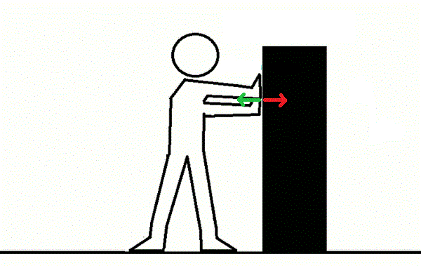
The reaction force (green arrow) increases as applied to the object increases, the force applied (red arrow)
- If one person pushes another of similar weight, the two move with the same speed but in the opposite direction.
- When we jump, we push the earth down, it does not move due to its great mass, and it pushes us with the same intensity upwards.
- A person rowing in a boat pushes the water with the paddle in one direction and the water responds by pushing the boat in the opposite direction.
- When we walk we push the earth backwards with our feet, to which the earth responds by pushing us forward, making us move forward.
- When a bullet is fired, the explosion of gunpowder exerts a force on the gun (which is the recoil suffered by firearms when fired), which reacts by exerting a force of equal intensity but in the opposite direction on the bullet.
- The reaction force that a surface exerts on an object resting on it, called a normal force with a direction perpendicular to the surface.
- The forces at a distance are not an exception, as the force that the Earth exerts on the Moon and vice versa, its corresponding pair of action and reaction:
The force exerted by the Earth on the Moon is exactly the same (and opposite) to that exerted by the Moon on Earth and its value is determined by the law of universal gravitation enunciated by Newton, which states that the force exerted by a object on another is directly proportional to the product of its masses, and inversely proportional to the square of the distance that separates them. The force that the Earth exerts on the Moon is responsible for it does not leave its circular orbit.
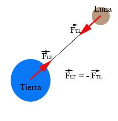
In addition, the force that the Moon exerts on the Earth is also responsible for the tides, because as the Moon revolves around the Earth it exerts a force of attraction on the Earth's surface, which raises the seas and oceans, raising several meters water level in some places; for this reason this force is also called tidal force. The tidal force of the moon is composed with the tidal force of the sun providing the complete phenomenon of the tides.
2.4(e) free body diagram &
Free body diagram: -
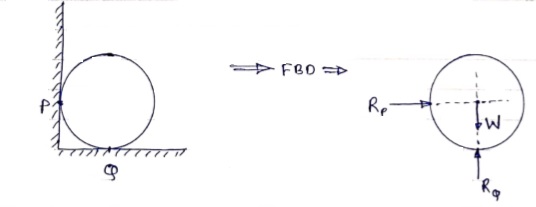
If a body is shown with all external forces acting on it so that the body is in equilibrium, such diagram is called as free body diagram.
To draw the free body diagram, we have to remove all the restrictions like wall, floor, hinge, any other support and replace them by reactions which these support extents on the body.
Ex – 1) Draw FBD of a bar supported and loaded as shown below.

2) Draw FBD of sphere supported as shown below.
2.4(f) Lami’s theorem
If three coplanar concurrent forces are in equilibrium then, the ratio of magnitude of any force to the sine of angle between the other two is constant.
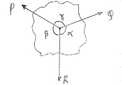
According to Lami’s Theorem:
Lami’s theorem can also be written as: If three coplanar concurrent forces acting at a point are in equilibrium, each force is proportional to the sine of angle between other two.
2.4(g) Tensions of strings
The concept of tension of strings is used to explain the transmission of forces from one point to another. Consider the system of a box that hangs at rest from a ceiling as shown below.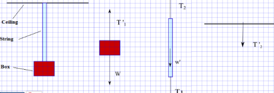
1) According to the free body diagram of the box, the forces acting on the box are: the weight of the box W and T '1 the force exerted by the string on the box.
Let x-y be a rectangular coordinate system and express W and T '1 by their components using magnitude and direction as follows:
W = (0 , -|W|) and T '1 = (0 , |T '1|)
Since the box is at rest, from Newton's second law, we have
W + T '1 = (0 , -|W|) + (0 , |T '1|) = 0
which gives
-|W| + |T '1| = 0 or |T '1| = |W|
T '1 and W have equal magnitude and opposite direction which explains why the box is at rest.
2) The forces acting on the string are the force T1 exerted by the box on the string as a reaction to T '1, T2 exerted by the ceiling on the string and w ' the weight of the string.
Using the same system of axes described above, we express T1, w ' and T2 in components form using magnitude and direction as follows
T1 = (0 , -|T1|)
T2 = (0 , |T2|)
w ' = (0 , -|w '|)
The string is also at rest, hence by Newton's second law, we have
T1 + T2 + w ' = (0 , -|T1|) + (0 , |T2|) + (0 , -|w '|) = 0
which gives
-|T1|+ |T2| - |w '| = 0
|T2| = |T1| + |w'|
If the weight of the string w ' is very small compared to |T2| and |T1|, it can be neglected and we end up with
|T2| = |T1|
Now since |T1| and |T2| are equal for mass less strings, the effect of the string is to transmit forces between distant points through the tension in the string.
Note the tension has the same magnitude everywhere for a mass less string (and frictionless pulley if used). The direction of the tension may or may not be the same.
T1 and T '1 are action-reaction pair and are therefore equal in magnitude and opposite side. T2 and T '2 are also action-reaction pair and are also equal in magnitude and opposite side. Hence we can finally write that
|T '1| = |T '2| which is mostly needed to solve problems involving strings, cords.
For a mass less string or cord, the tension is the same everywhere.
2.4(h) Condition of equilibrium for coplanar concurrent forces
The sum of all forces in the x-direction or horizontal is zero.
ΣFx=0ΣFx=0 or ΣFH=0ΣFH=0
The sum of all forces in the y-direction or vertical is zero.
ΣFy=0ΣFy=0 or ΣFV=0ΣFV=0
Important Points for Equilibrium Forces
- Two forces are in equilibrium if they are equal and oppositely directed.
- Three coplanar forces in equilibrium are concurrent.
- Three or more concurrent forces in equilibrium form a close polygon when connected in head-to-tail manner.
2.4(i) coplanar non-concurrent forces
It is defined as the forces which lies in the line of activity but do not intersect or forms a parallel at a common point. The forces are the general system of forces.
Show the non-concurrent, non-parallel systems in figure (1).
Coplanar = within the same plane.
Concurrent = passing through the same point.
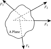
In figure (1), there are four forces; F1, F2, F3 and F4 respectively. These forces act on a single A plane.
Consider an example for non-concurrent, non-parallel systems. A man is standing on the ladder which is resting against a wall. Here, the forces on the ladder do not meet at a common point but it lies on a single plane which is the wall.
The resultant of non-concurrent, non-parallel systems is obtained by the principles of equilibrium. In non-concurrent force system, consider three equilibrium conditions; force equilibriums in x-direction and y&-direction, and moment equilibrium by the sum of moments about point O.
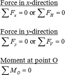
The pair of force system is solved graphically along with parallelogram or triangle law. After calculating the pair of forces, calculate the resultant of the forces and combine it to determine the new resultant.
2.4(j) Equilibrium of Coplanar concurrent forces
Concurrent means that the forces intersect through a single point.
If forces are concurrent, we can add them together as vectors to get the resultant.
If the body is not accelerating, it must be in equilibrium, so that means the resultant is zero
For concurrent forces, the body is a point.
So for concurrent forces in equilibrium, the forces should all add up to give zero.
If a body is not accelerating is in equilibrium, so resultant of all forces = 0.
A typical concurrent force situation is a lifting eye. The pulling forces in any cables must pass through the centre of the eye. If there is only one eyebolt (correctly positioned over the centre of gravity) and the load is suspended, the bolt force must pass through the same centre. Hence all forces pass through one point (the centre of the eye), so we have concurrent equilibrium.
2.4(k) Equilibrium of Coplanar non-concurrent forces
There are three equilibrium conditions that can be used for non-concurrent, non-parallel force system.
The sum of all forces in the x-direction or horizontal is zero.
ΣFx=0ΣFx=0 or ΣFH=0ΣFH=0
The sum of all forces in the y-direction or vertical is zero.
ΣFy=0ΣFy=0 or ΣFV=0ΣFV=0
The sum of moment at any point O is zero.
ΣMO=0ΣMO=0
The three equilibrium conditions can solved up to three unknowns in the system. If the system involves more than three unknowns, it is called indeterminate.
2.5(a) Force in space
- The force system which is acting in different planes is called as non – coplanar force system or space force.
- If a force is defined by three co-ordinates axis then it is called as space force.
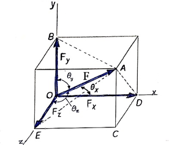
Rectangular components of force in space:-
Let us consider the force F which is acting along the diagonal OA as shown above and making angles ØX, ØY, ØZ, with x,y,z axis respectively.
The above forces F in a three dimensional space can be resolved into rectangular components FX, FY, FZ.
Then
Fx = F cosØX
FY = F cosØy
FZ = F cosØZ

Here cosØX, cosØy, cosØZ are the cosines ofØX,Øy , ØZ and are known as directions cosine of force F.
The force vector  can be expressed as ;
 = (FX i + FY j + FZ k)
 = (FcosØX i + FcosØy j + FcosØZ k)
 = F(cosØX i + cosØy j + cosØZ k)
 = F.
= F.
In above equation,
F = magnitude of force
 = unit vector along the direction of force.
 = (cosØX i + cosØy j + cosØZ k)
Here, cos2 ØX + cos2 ØY + cos2 ØZ = 1
Direction cosines can be found only by,
CosØX = 
CosØY = 
CosØZ = 
When force F is defined in three dimensional space by using two points on its line of action, then rectangular components can be obtained as follows.
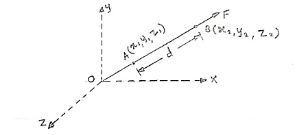
Consider force F acting at point O. Let A(x1,y1,z1)& B(x2,y2,z2) are the two points on the line of action of force F.
Let distance between two points (on the line of action of force) A & B is ‘d’.
Now
Vector  dx i + dy j + dz k
Magnitude of AB = d = 
We know that vector = magnitude × unit vector along AB
 AB
AB
 AB =
AB = 
 AB = (dx I + dy j + dz k) ×
We know that force  = magnitude x unit vector along line of action
 = F ×
= F ×  AB
AB
 =
=  (dx i + dy j + dz k)
 =
= 
From above equation we can have three components of force,
Fx = 
Fy = 
FZ = 
Unit vector along direction of force
 AB =
AB = 
eAB = 
eAB =  unit vector
Position vector
- Consider force F passing through point Q (x2, y2, z2)
- Let P (x1, y1, z1) is point away from line of action.
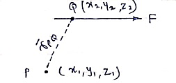
Then,
 PQ = position vector of P w.r.t. Q
= dx I + dy j + dz k
 PQ = (x2-x1)i + (y2 – y1)j + (z2-z1)k
r = 
Resultant of several forces in space :-
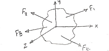
Consider a body on which forces F1 , F2 , F3 , F4 are acting as shown in figure.
R = Rx i + Ry j + Rz k
Rx = Resultant in x direction = ∑Fx = Fx1 + Fx2 + Fx3 + Fx4
Ry = Resultant in y direction = ∑Fy = Fy1 + Fy2 + Fy3 + Fy4
Rz = Resultant in z direction = ∑Fz = Fz1 + Fz2 + Fz3 + Fz4
R = 
Direction of resultant w.r.t. x,y,z axis is


Moment of force in space about point
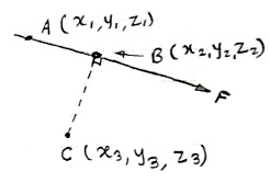
Consider a force  = Fx i + Fy j + Fz k is passing through two points A(x1, y1, z1) & B(x2, y2, z2) as shown.
Then moment of this force about point C(x3, y3, z3) will be
Mc =  CA ×
CA × 
Mc =| |
|
Here, [ rx = (x1 – x3), ry = (y1 – y3) & rz = (z1 – z3)]
Mx = (ryFZ - rZFZ)
My = (rZFX - rXFZ)
Mz = (rXFY - rYFX)
Mc = 
2.5(b) Resultant of concurrent forces in space
Consider the force of magnitude F passing through the points A(x1,y1,z1) & B(x2,y2,z2).
Consider any line passing through the points P(x3,y3,z3) & Q(x4,y4,z4)
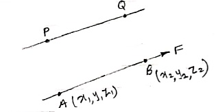
Moment of this force about line PQ is given by,
 =
=  .
. 
Rectangular components of force in space
- Fx = F cosØX
- FY = F cosØy
- FZ = F cosØZ
ØX = angle of force with x-axis
Øy = angle of force with y-axis
ØZ = angle of force with z-axis

Force vector (in space) :
 = (FX i + FY j + FZ k)
 = F ×
= F ×  AB
AB
 = unit vector along the direction of force.
eAB = 
Moment of force in space about a point
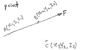
Moment of force F about point C is given by,
Mc =  CA ×
CA × 
Solving above equation we will get moment vector moment vector,
Mc = 
Varingnon’s theorem for forces in space
∑M = MR
Sum of moment of all forces about a point= moment of resultant about same point
Moment of Force about a line:
Key points :- moment of force will be zero if
- A line (about which moment is taken) is parallel to force
- If force intersects the line about which the moment is to be taken.
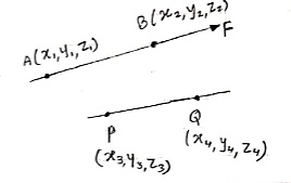 The moment of force about a line PQ is
 =
=  .
. 
Where, Mp =  PA ×
PA × 
Resultant of forces in space
RX = ∑FX = Fx1 + Fx2 + ……
RY = ∑FY = Fy1 + Fy2 + ……
RZ = ∑FZ = Fz1 + Fz2 + ……
R =  =
= 
Direction of resultant is ;
Cosαx =  =
= 
Cos αy =  =
= 
Cos αz =  =
= 
Equilibrium of concurrent & parallel forces in space :
 = 0
= 0  = 0
= 0
 = 0
= 0  = 0
= 0
 = 0
= 0  = 0
= 0
The equilibrium particle in space can be understood by solving numerical which is given below.
Question 1. The cable exert a force FAB = 100N & FAC = 120 N on the ring at point A as shown in figure. Determine the magnitude of the resultant force acting at A.
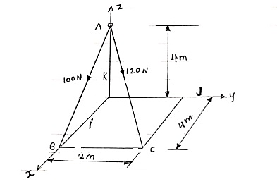
 Express the forces in terms of force vector
 = FAB ×
  AB
AB
= 100 
= 100
= 100
= 100(0.70 i + 0 j - 0.70 k)
= 70.7 i + 0 j – 70.7 k --------(1)
Now,
 AC = FAC ×
  AC
AC
= 120 
= 120
= 120
= 120(0.667 i + 0.333 j - 0.667 k)
= 80.04 i + 39.6 j – 80.04 k ----------(2)
From equation (1) & (2)
RX = ∑FX = 70.7 + 80.04 = 150.11 N
RY = ∑FY = 0 + 39.6 = 39.6 N
RZ = ∑FZ = -70.7 – 80.04 = -150.11 N
R = 
= 
R = 216 N
Direction of resultant is ;
αx = 
αy = 
αz = 
Que 2. If each cable can sustain a maximum tension of 600 N. Determine the greatest weight of bucket and its contents that can be supported. Refer the figure.
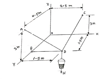
 Force developed in each cable will be tension, then, force vectors can be written as below,
(i)  DB = TDB ×
  DB
DB
= TDB
= TDB
= TDB(-1 i + 0 j + 0 k)
= - TDBi + 0 j + 0 k
(ii)  DA = TDA ×
  DA
DA
= TDA
= TDA
= TDA (- 0.333i + 0.667j + 0.677k)
= (- 0.333TDA )i + (0.677TDA) j + (0.667TDA)k
(iii)  DC = TDC ×
  DC
DC
= TDC
= TDC
= TDC (0.286 i –0.428 j + 0.857 k)
= (0.286TDC)i –(0.428TDC)j + (0.857TDC)k
(iv)  = -W.k = 0i + 0j – wk
Now applying equilibrium conditions,
∑Fx = 0
-TDB – 0.33 TDA + 0.286 TDC + 0 = 0 --------(1)
∑Fy = 0
0+ 0.667 TDA - 0.428 TDC + 0 = 0 --------(2)
∑Fz = 0
0+ 0.667 TDA + 0.857 TDC - w = 0 --------(3)
Now it is given that each cable can sustain maximum tensionof 600 N. Thus our answer must be less than 600 or equal to 600 N.
(a) TDA = 600 N, then solving equation (1), (2) & (3) we get
TDB = 69.42 N
TDC = 935 N
W = 1201 N
Here tension in one cable is more than 600 N which is not allowed.
(b) TDB = 600 N , then solving equation (1), (2) & (3) we get
TDA = 5185 N
TDC = 8081 N
W = 10384 N
Here tension in the cables is more than 600 N which is not allowed.
(c) TDC = 600 N , then solving equation (1), (2) & (3) we get
TDB = 44.54 N
TDA = 385 N
W = 771 N
Here tension in each cable is less than 600 N. Thus this answer is correct
Weight of bucket = w = 771 N
Que 3. The ball is suspended from the horizontal ring using three springs each having stiffness of k = 50 N/m and an unstretched length of 1.5m. If h = 2m, determine the weight of ball. Refer the figure.

 The length of each spring is
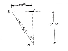 L =
L = 
L = 2.5 m
Unstretched length of spring
L0 = 1.5 m
Deflection of spring
X = L – L0 = 2.5 – 1.5
X = 1 m
Force developed in each spring = kx = 50×1 = 50N
As shown in figure, each spring makes Ø angle with vertical
Sin Ø = 
Ø = 36.87 ˚
Y component of each spring force will be =
Fy = F cosØ = 50 cos 36.87 = 40 N
For equilibrium,
∑Fx = 0
-w + 3(Fy) = 0
-w + 3 × 40 = 0
W = 120 N ---------- weight of ball