UNIT 2
Electrical Circuit Analysis
Kirchhoff Current Law:
A node is a circuit connection that extends to all its neighbouring elements but does not contain them.
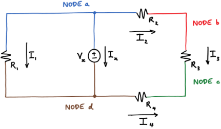
Kirchhoff’s current law states that at a node:
Sum of the in currents = sum of out currents
Applying KCL at four nodes
0 = Ix + I1 + I2 KCL at node a
I2 = I3 KCL at node b
I3 + I4 = 0 KCL at node c
Ix + I1 = I4 KCL at node d
Adding equations 6-9 gives the following equation:
Ix + I1 + I2 + I3 + I4 = Ix + I1 + I2 + I3 + I4.
Kirchhoff Voltage Law:
A loop is a path around a circuit that starts and ends in the same place.
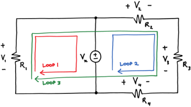
Kirchhoff's voltage law (KVL) states that around a loop:
Sum of voltage rises=sum of voltage drops--------------------(1)
Applying KVL around the three loops we get
V1 = Vx KVL around loop 1
Vx + V4 = V2 + V3 KVL around loop2
V1 + V4 = V2 + V3 KVL around loop3
Find the voltage across the current source and the current passing through the voltage source.
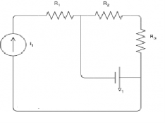
R1 is in series with the current source; therefore, the same current passing through it as the current source:
IR1=I1=3A
and the voltage across R1 can be found by Ohm's law:
VR1=R1×IR1=2×3=6V
To find the voltage across the current source, KVL can be applied around the left- hand side loop:
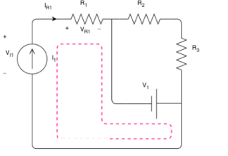
The direction does not matter and would not change the result.
−VI1+VR1−V1=0A
VI1=VR1−V1=6−15=−9V
R2 and R3 are also in series and their equivalent is R23=R2+R3=3Ω+2Ω=5Ω
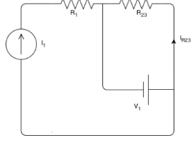
R23 is parallel with the voltage source. This means that its voltage is equal to the voltage of the voltage source.
VR23=V1=15V
Now, using the Ohm's law, the current passing through R23 can be calculated:
IR23=VR23/R23=15/5=3A
To find the current of the voltage source, we can apply KCL at one of the nodes:
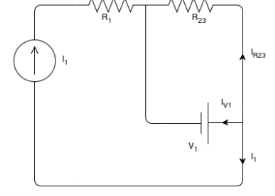
IR23+I1+IV1=0
IV1=−IR23−I1=−3−3=−6A
Find out V1 and V2 using KVL.
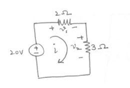
-20 + v1 + v2 =0 ------------------------(1)


 V1 = 2i from the circuit
 V2 = 3i
Therefore
-20 + 2i + 3i =0
5i = 20
i=4A
v1 = 2i = 2(4) = 8V
v2 = 3i = 3(4) = 12V
Find the current io and voltage vo as shown in the figure using KCL .
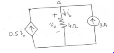
At node ‘a’
0.5 io + 3 -io =0
3 – 0.5 io = 0
Io=6A
Vo = 4io
Vo = 4(6) = 24 V
Nodal analysis
In the nodal method we are finding the node voltages with the following steps:
- Select a reference node. Assign all the rest nodes voltages , with respect to reference node.
- Use Kirchhoff’s and Ohm’s Laws to each non-reference node and branch currents.
- Resolve the system of equations and obtain node voltages.
Consider the following circuit.
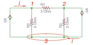
Let us consider a reference node – 3.
In a real circuit a reference node is ground is assumed to have potential.
By the Kirchhoff’s Law having the following current relation:
I1 = i1 + i2
I2 = i2 -i3
Let us represent currents like ratio of voltage and resistance by the Ohm’s Law:
i 1 = v1 /R1 ; i 2 = v1 -v2 /R2 ; i3 = v2/R3;
Or
i 1= v1 * G1 ; i2 =(v1 -v2)*G2 ; i3 =v2 * G3
i1 = v1 * G1 + (v1-v2) * G2 ;
i2 = (v1-v2) * G2 – v2 * G3
i1= v1 * (G1 +G2) – v2 * G2
i2 = v1 *G2 – v2 *(G3 +G2)
Or
And we achieve the following matrix equation, which can be resolved by the Cramer’s rule:
[ G1 + G2 -G3 -G3 ] [v1] = [I1]
[ G2 -G2][v2] =[I2]
Consider the following figure :
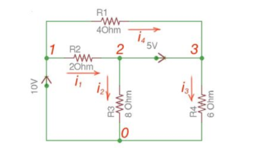
There are two possibilities that exist:
- If the voltage source is between reference node and non-reference node, the non-reference voltage is considered equal to the voltage source.
- If the voltage source is between two non-reference nodes, these two nodes are generalised nodes. To determine its voltage Kirchhoff’s Laws must be applied.
Applying Kirchhoff’s Law we achieve the following equations:
i 1 + i4 = i2 + i3
-v2 +5+v3 =0
v 1 =10
By Ohm’s Law
These equations will help determine node voltages.
Mesh Analysis
Mesh analysis is applicable to the networks which are planar. Planar network is a network where branches are not passing over or under each other.
Nodal method uses Kirchhoff’s currents Law to consider nodal voltages, and Mesh method uses Kirchhoff’s voltages Law to consider mesh currents. Mesh is a loop, which does not contain any other loops.
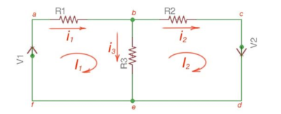
There are only two meshes in abefa and bcdeb, abcdefa is not a mesh but a loop However, for Mesh method only meshes are in use.
Mesh analysis steps are the following:
- Assign mesh currents to all the meshes in a circuit.
- Apply Kirchhoff’s voltage Law to each mesh. Apply Ohm’s Law to determine voltages with mesh currents.
- To resolve simultaneously all the equations to consider mesh currents.
The following equations correspond to the Kirchhoff’s Voltage Laws for the meshes:
V1 = i1 *(R1+R3) – i2 *R3
-V2 = -i1 *R3 + i2 * (R3 +R2);
[ R1 +R3 -R3 [i1]= [V1]
-R3 R2+R3] [i2] = [V2]
Using Cramer’s formula for resolving the matrix equations above we can find mesh currents.
I1 =i 1 I2 = i2 I1 -I2 =i3
Find the current flowing through 20 Ω resistor of the following circuit using Nodal analysis.

Step 1 − There are three principle nodes in the above circuit. Those are labelled as 1, 2, and 3 in the following figure. In the above figure, consider node 3 as reference node (Ground).

Step 2 − The node voltages, V1 and V2, are labelled in the following figure.
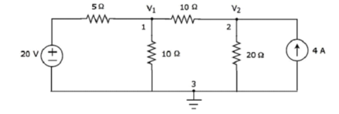
Step 3 – There are two nodal equations, since there are two principal nodes, 1 and 2, other than Ground.
The nodal equation at node 1 is
V1 -20/5 + V1/10 + V1-V2/10 =0
2V1 -40 +V1+V1-V2/10 =0
4V1 -40-V2 =0 --- V2 = 4V1-40 -------(1)
The nodal equation at node 2 is
-4 +V2/20 + V2-V1/10 =0
-80 + V2 + 2 V2 – 2V2/ 20 =0
= 3V2 -2V1 =80 --------------(2)
Step 4 − Finding node voltages, V1 and V2 by solving Equation 1 and Equation 2.
Substitute Equation 1 in Equation 2.
3(4V1−40)−2V1=80
⇒12V1−120−2V1=80
⇒10V1=200
⇒V1=20V
Substitute V1 = 20 V in Equation1.
V2=4(20)−40
⇒V2=40V
So, we got the node voltages V1 and V2 as 20 V and 40 V respectively.
Step 5 − The voltage across 20 Ω resistor is nothing but the node voltage V2 and it is equal to 40 V. Now, we can find the current flowing through 20 Ω resistor by using Ohm’s law.
I 20Ω = V2/R
Substitute the values of V2 and R
I 20 Ω = 40/20
I 20Ω = 2A
Therefore, the current flowing through the 20Ω resistor is 2A.
Find the voltage across 30 Ω resistor using Mesh analysis.

Step 1 − There are two meshes in the above circuit. The mesh currents I1 and I2 are considered in clockwise direction. These mesh currents are shown in the following figure.

Step 2 − The mesh current I1 flows through 20 V voltage source and 5 Ω resistor. Similarly, the mesh current I2 flows through 30 Ω resistor and -80 V voltage source. But, the difference of two mesh currents, I1 and I2, flows through 10 Ω resistor, since it is the common branch of two meshes.
Step 3 − Since there are two meshes in the given circuit write the mesh equations, assume the mesh current of that particular mesh as greater than all other mesh currents of the circuit.
The mesh equation of first mesh is
20−5I1−10(I1−I2)=0
⇒20−15I1+10I2=0
⇒10I2=15I1−20
Divide the above equation with 5.
2I2=3I1−4
Multiply the above equation with 2.
4I2=6I1−8-----------------(1)
The mesh equation of second mesh is
−10(I2−I1)−30 I2+80=0
Divide the above equation with 10.
−(I2−I1)−3I2+8=0
⇒−4I2+I1+8=0-----------------(2)
4I2 = I1 +8
Step 4 − Finding mesh currents I1 and I2 by solving Equation 1 and Equation 2.
The left-hand side terms of Equation 1 and Equation 2 are the same. Hence, equate the right-hand side terms of Equation 1 and Equation 2 in order find the value of I1.
6I1 -8 = I1 +8
5I1 =16
I1 = 16/5 A
Hence, 4I2 = 16/5 + 8
4I2 = 56/5
I2 = 56/20 = 2.8 A
Step 5 − The current flowing through 30 Ω resistor is nothing but the mesh current I2 and it is equal to 14/5 A. The voltage across 30 Ω resistor by using Ohm’s law.
V 30 Ω = I2 R
V30Ω = (14/5) x 30 = 84V
Series and parallel circuit
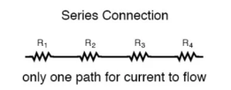
The basic idea of a “series” connection is that components are connected end-to-end in a line to form a single path through which current can flow:
Series connection
Parallel connection:
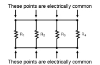
The basic idea of a “parallel” connection, on the other hand, is that all components are connected across each other’s leads. In a purely parallel circuit, there are never more than two sets of electrically common points, no matter how many components are connected. There are many paths for current flow, but only one voltage across all components:
Current and voltage division rule
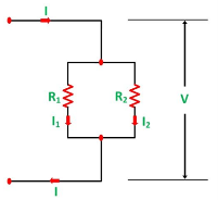
A parallel circuit acts as a current divider as the current divides in all the branches in a parallel circuit, and the voltage remains the same across them. The current division rule determines the current across the circuit impedance. The current division is explained with the help of the circuit shown below:
The current I has been divided into I1 and I2 into two parallel branches with the resistance R1 and R2 and V is the voltage drop across the resistance R1 and R2.
As we know,
V = IR ……..(1)
Then the equation of the current is written as:
I1 = V/R1 and I2 = V /R2
Let the total resistance of the circuit be R and is given by the equation shown below:
R = R1R2/ R1 + R2
Equation (1) can also be written as:
I = V/R ……….(3)
Now, putting the value of R from the equation (2) in the equation (3) we will get
I = V(R1+R2)/ R1R2 ---------------------------(4)
But
V = I1 R1 = I2 R2 ------------------------------(5)
Putting the value of V = I1R1 from the equation (5) in equation (4), we finally get the equation as:
I = I1R1(R1+R2)/ R1R2 = I1(R1+R2)/ R2---------------------(6)
And now considering V = I2R2 the equation will be:
I = I2R2(R1+R2)/ R1R2 = I1/R1 (R1+R2) ------------------------------(7)
Thus, from the equation (6) and (7) the value of the current I1 and I2 respectively is given by the equation below:
I1 + I . R2/ R1 + R2 and I2 = I . R1 / R1 + R2
Thus, in the current division rule, it is said that the current in any of the parallel branches is equal to the ratio of opposite branch resistance to the total resistance, multiplied by the total current.
Voltage Division Rule
The voltage division rule can be understood by considering a series circuit shown below. In a series circuit, voltage is divided, whereas the current remains the same.
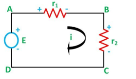
Let us consider a voltage source E with the resistance r1 and r2 connected in series across it.
As we know,
I = V/R or we can say I = E/R
Therefore, the current (i) in the loop ABCD will be:
i = E / r1 + r2 -------------------------(8)
And r1 = ir1
By putting the value of I from equation (8) in equation (9) the voltage across the resistance r1 and r2 respectively are given by the equation shown below as:
E1 = Er1/r1 + r2 and E2 = E r2/ r1 + r2
Thus, the voltage across a resistor in a series circuit is equal to the value of that resistor times the total impressed voltage across the series elements divided by the total resistance of the series elements.
For the following circuit
- Find the total resister value RT
- Find the current i
- Find the voltage over resistors
- Verify Kirchhoff’s voltage law
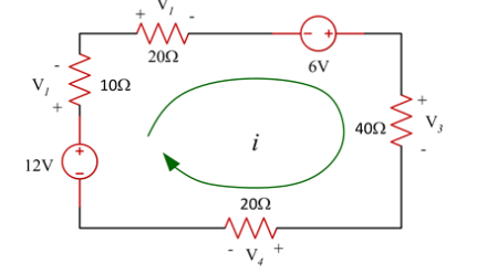
Solution
RT = 10+20+40+20 = 90 Ω
i = V/RT = (12+6)/ RT = 18/RT = 18/90 =0.2 = 200mA
V1 = 10 x 0.2 = 2V
V2 = 20(0.2) = 4V
V3 = 40x 0.2 = 8V
V4 = 20(0.2) = 4V
V1 + V2 -6 + V3 + V4 -12 =0
2 + 4 – 6 + 8 + 4 -12 =0
Figure shows resistors wired in a combination of series and parallel. We can consider R1 to be the resistance of wires leading to R2 and R3.
(a) Find the equivalent resistance of the circuit.
(b) What is the potential drop V1 across resistor R1?
(c) Find the current I2 through resistor R2?.
(d) What power is dissipated by R2?
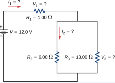
Solution
- To find the equivalent resistance of the circuit, notice that the parallel connection of R2 and R3 is in series with R1, so the equivalent resistance is
Req=R1+(1R2+1R3).
Req = R1 + R2.R3 / R2 + R3
= 1 + 6x13/6+13 = 1+ 4.10 = 5.10 Ω
2. The current through R1 is equal to the current supplied by the battery:
I1=I=V/ Req=12.0V/5.10Ω = 2.35 A
The voltage across R1 is
V1=I1R1=(2.35A)(1Ω)=2.35V.
The voltage applied to R2 and R3 is less than the voltage supplied by the battery by an amount V1.
When wire resistance is large, it can significantly affect the operation of the devices represented by R2 and R3.
To find the current through R2, we must first find the voltage applied to it.
The voltage across the two resistors in parallel is the same:
V2=V3=V−V1=12.0V−2.35V=9.65V.
3.Now we can find the current I2 through resistance R2 using Ohm’s law:
I2=V2/R2=9.65V/6.00Ω=1.61A.
4.The power dissipated by R2 is given by
P2=I22R2=(1.61A)2(6.00Ω)=15.5W
Delta-star conversions
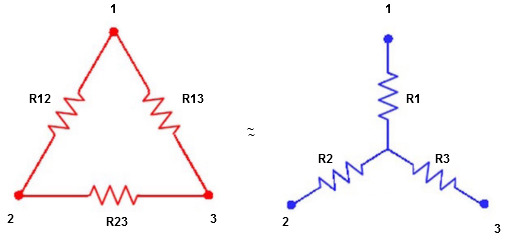
We know that (from delta to star conversion)
R1 =  …….①
…….①
R2 =  …..②
…..②
R1 =  ……③
……③
Multiply ① X ② L.H.S and R.H.S
R1 R2 =  …….④ where
Similarly, multiply ② X ③
R2 R3 =  …….⑤
…….⑤
And ③ X①
R1 R3 =  …….⑥
…….⑥
Now add equation ④, ⑤, and ⑥ L.H.S and R.H.S


 ……refer eq. ②
 =
=  +
+  +
+ 
 =
=  +
+ 
Delta to Star Conversion to Find (Req.)
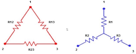
- Equivalent resistance between ① and ②
Delta  Star
Star
= R12// (R23 + R13) =R1 + R2
= 
 = R1 + R2
= 

Here let R = R12 + R23 + R13
- Similarly, we can find Req. Between 2 and 3
= 
 R2 + R3
- Similarly, we can find req. Between 1 and 3

 R1 + R3
Now the 3 equations after equating L.H.S. And R.H.S
R1 + R2 =  …….①
…….①
R2 + R3 =  ……②
……②
R1 + R3 =  …..③
…..③
Now subtract ② and ① on L.H.S. And R.H.S
R2+ R3 – R1 – R2 = 
 R3 – R1 =
  …..④
…..④
Now add equation ④ and ③
R3 – R1 + R1 + R3 = 
2R3 = 

Similarly, R1 = 
And R2 = R23 R12/R where R = R12 + R23 + R13
i.e. star equivalent from delta network is the ratio of the product of adjacent branches in the delta to the addition of all branches in the delta.
Potential Divider
A potential divider is a simple circuit that uses resisters(or thermistors / LDR’s) to supply a variable potential difference.
They can be used as audio volume controls, to control the temperature in a freezer or monitor changes in light in a room.
Two resistors divide up the potential difference supplied to them from a cell. The proportion of the available p.d. That the two resistors depends on the resistance values.
- Vin = p.d. Supplied by the cell
- Vout = p.d. Across the resistor of interest
- R1 = resistance of resistor of interest R1
- R2= resistance of resistor R2
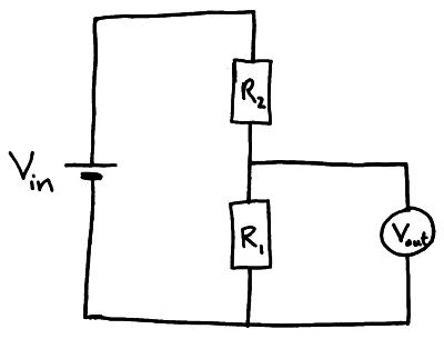

Example; use the information in the diagram below to find Vout.
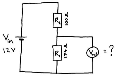
Vout = 12x 174/100 +174 = 7.6 V
References:
- Electronic Devices And Circuits Theory 10th Edition (English, Paperback, Robert L. Boylestad, Louis Nashelsky)
Electronic Principles Textbook by Albert Paul Malvino
How to Diagnose and Fix Everything Electronic, Second Edition Book by Michael Jay Geier
- Principles of Electronics is a 2002 book by Colin Simpson
Starting Electronics Book by Keith Brindley