UNIT 3
Electrostatic
- A capacitor is a passive two-terminal electrical component used to store energy electrostatically in an electric field.
- All contain at least two electrical conductors (plates) separated by a dielectric (i.e., insulator).
- Capacitors are widely used as parts of electrical circuits in many common electrical devices. Unlike a resistor, a capacitor does not dissipate energy.
- The capacitor stores energy in the form of an electrostatic field between its plates.
- When there is a potential difference across the conductors (e.g., when a capacitor is attached across a battery), an electric field develops across the dielectric, causing positive charge (+Q) to collect on one plate and negative charge (-Q) to collect on the other plate.
- If a battery has been attached to a capacitor for a sufficient amount of time, no current can flow through the capacitor.
- However, if an accelerating or alternating voltage is applied across the leads of the capacitor, a displacement current can flow.
- Capacitance is expressed as the ratio of the electric charge (Q) on each conductor to the potential difference (V) between them.
- The SI unit of capacitance is the farad (F), which is equal to one coulomb per volt (1 C/V).
Charge and voltage:
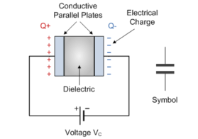
- The parallel plate capacitor is constructed using two metal or metallised foil plates at a distance parallel to each other, with its capacitance value in Farads, being fixed by the surface area of the conductive plates and the distance of separation between them.
- The capacitors store the energy of the electrons in the form of an electrical charge on the plates the larger the plates and/or smaller their separation the greater will be the charge that the capacitor holds for any given voltage across its plates. In other words, larger plates, smaller distance, more capacitance.
- By applying a voltage to a capacitor and measuring the charge on the plates, the ratio of the charge Q to the voltage V will give the capacitance value of the capacitor and is therefore given as:
C = Q/V
- When an electric current flow into the capacitor, it charges up, so the electrostatic field becomes much stronger as it stores more energy between the plates.
Capacitance
Capacitance is the electrical property of a capacitor and is the measure of a capacitors ability to store an electrical charge onto its two plates with the unit of capacitance being the Farad.
Capacitance is defined as being that a capacitor has the capacitance of One Farad when a charge of One Coulomb is stored on the plates by a voltage of One volt.
Electric fields
An electric field is a field or space around an electrically charged object where any other electrically charged object will experience force.
An electric field is measured by electric field intensity. If we place a positive unit charge near a positively charged object, the positive unit charge will experience a repulsive force.
Due to this force, the positive unit charge will move away from the said charged object. The imaginary line through which the unit positive charge moves, is known as line of force.
.
If we place a positive unit in the field of a negatively charged object, the unit positive charge will experience an attractive force. Due to this force, the unit positive charge will come closer to the said negatively charged object. In that case, line through which the positive unit charge moves, is called line of force.

When we place a unit positive anywhere surround the positively charged object and each position where we place it, the unit positive charge follows a separate line force to move.
Hence, we can say, the lines of force gets radiated or come out from this charged object.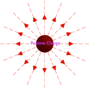
But for a negatively charged object, these lines of force come into this negatively charged object.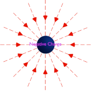
Electric field strength and electric flux density
Electric field strength can be determined by Coulomb’s. According to this law, the force ‘F’ between two-point charges having charge Q1 and Q2 Coulombs and placed at a distance d meter from each other is given by,

 = Q1 Q2 / 4 π ꙴ o ꙴ r d 2 ------------------------------(1)
Here, εo is the permittivity of vacuum = 8.854 × 10 – 12 F/m and εr is the relative permittivity of the surrounding medium.
Let us put Q2 = + 1 Coulomb and let us denote force F by E in the equation (1), and by doing these we get, ------------------------------------------(2)
This equation shows the force acting by a unit positive charge placed at a distance d from charge Q1.
Therefore, electric field strength of charge Q1 at a distance d from that charge which is given by

The above expression shows that, if we place a charge at any point in an electric field, the product of the electric field strength at that point and the charge of the body gives the force acting on the body at that point in the field.
The above expression can also be rewritten as,
Electric flux density
Electric flux density is defined as the amount of flux passes through unit surface area in the space imagined at right angle to the direction of electric field. The expression of electric field at a point is given by
Where, Q is the charge of the body by which the field is created.
R is the distance of the point from the center of the charged body. As, we know, Q = Ψ
The above equation can be rewritten as,
This is the expression of flux per unit area since, 4πr2 is the surface area of the imaginary spare of radius r. This is the flux passing through per unit area at a distance r from the center of the charge. This is called electric flux density denoted by D. Therefore,
Relative permittivity
It is defined as the permittivity of a given material relative to that of the permittivity of a vacuum. It is normally symbolised by: εr.
ε=D/E
ε = permittivity of the substance in Farads per metre
D = electric flux density
E = electric field strength
It can be seen from the definitions of permittivity that constants are related according to the following equation:
εr=εs/ε0
Where:
εr = relative permittivity
εs = permittivity of the substance in Farads per metre
ε0 = permittivity of a vacuum in Farads per metre
Dielectric strength
Dielectric Strength reflects the electric strength of insulating materials at various power frequencies. Or it can be defined as the measure of dielectric breakdown resistance of a material under an applied voltage and is expressed as Volts per unit thickness.
Problems:
Find the capacitance of a layer of Al2O3that is 0.5 m thick and 2000 mm2 of square area ( r = 8.854 × 10⁻¹² Fm–1)
Solution:
Given data:
Permittivity of free space : = 8.854 x 10 -12
Area of capacitance A = 2000 mm 2
Thickness d = 0.5 x 10 -6 m
C = ꙴ r ꙴ o A/d = 8.854 x 10 -12 x 2000 x 10 -6 / 0.5 x 10 -6
C = 3.5416 x 10 -8 F
If an ionic crystal is subjected to an electric field of 1000 Vm–1 and the resulting polarization 4.3 × 10⁻⁸ cm2. Calculate the relative permittivity of NaCl.
Solution:
Electric field E = 1000 V/m
ε0 = 8.854 x 10 -12 F/m
P = 4.3 x 10 -8 cm2
P = ꙴ o (ꙴ r -1) E
ꙴ r = 1 + P / ε0 E
ꙴ r = 1 + P / ε0 E
ꙴ r = 1 + 4.3 x 10 -8 / (8.85 x 10 -12 x 100)
ꙴ r = 5.86
The capacitors C1, C2 and C3 are all connected together in a parallel branch between points A and B as shown.
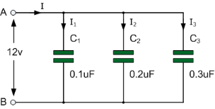
When capacitors are connected together in parallel the total or equivalent capacitance, CT in the circuit is equal to the sum of all the individual capacitors added together.
This is because the top plate of capacitor, C1 is connected to the top plate of C2 which is connected to the top plate of C3 and so on.
Then it is the same as if the three sets of plates were touching each other and equal to one large single plate thereby increasing the effective plate area in m2.
Since capacitance, C is related to plate area
C = ε(A/d) ) the capacitance value of the combination will also increase.
The total capacitance value of the capacitors connected together in parallel is actually calculated by adding the plate area together.
In other words, the total capacitance is equal to the sum of all the individual capacitance’s in parallel.
The currents flowing through each capacitor is given by
i 1 = C1 dv/dt i2 = C2 dv/dt i3 = C3 dv/dt
iT = i1 + i2 + i3
iT = C1 dv/dt + C2 dv/dt + C3 dv/dt
And this can be re-written as:
iT = (C1 + C2 + C3 ) dv/dt
Or iT = CT . Dv/dt
Calculate the combined capacitance in micro-Farads (μF) of the following capacitors when they are connected together in a parallel combination:
- a) two capacitors each with a capacitance of 47nF
- b) one capacitor of 470nF connected in parallel to a capacitor of 1μF
a) Total Capacitance,
CT = C1 + C2 = 47nF + 47nF = 94nF or 0.094μF
b) Total Capacitance,
CT = C1 + C2 = 470nF + 1μF
Therefore, CT = 470nF + 1000nF = 1470nF or 1.47μF
Capacitors in a Series Connection
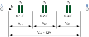
In the series circuit the right hand plate of the first capacitor, C1 is connected to the left hand plate of the second capacitor, C2 whose right hand plate is connected to the left hand plate of the third capacitor, C3. Then this series connection means that in a DC connected circuit, capacitor C2 is effectively isolated from the circuit.
The result of this is that the effective plate area has decreased to the smallest individual capacitance connected in the series chain.
Therefore, the voltage drop across each capacitor will be different depending upon the values of the individual capacitance’s.
Then by applying Kirchhoff’s Voltage Law, ( KVL ) to the above circuit, we get:
VAB = VC1 + VC2 + VC3 = 12V
VC1 = QT/C1 , VC2 = QT/C2, VC3= QT/C3
Since Q = C*V and rearranging for V = Q/C, substituting Q/C for each capacitor voltage VC in the above KVL equation will give us:
VAB = QT /CT = QT/C1 + QT/C2 + QT/C3
Example :
Taking the three capacitor values from the above example, we can calculate the total capacitance, CT for the three capacitors in series as:
1/CT = 1/0.1 μ F + 1/0.2 μF + 1/0.3 μF = 1/ 18.33 x 10 -6
CT = 0.055 μF or 55nF
Calculation of capacitance of parallel plate and multi plate capacitor
The capacitance of the parallel plate capacitor determines the amount of charge that it can hold. The capacitance depends upon:
- The distance d between two plates.
- The area A of the medium between the plates.
According to the Gauss law, we can write the electric field as:
E = Q/  . A = Ed = V = Qd/
  . d
. d
Since we know that the capacitance is defined as V = Q/C, so we can write capacitance as:
C =  . A / d
When the plates are placed very close and the area of plates are large, we get the maximum capacitance.
The condition of parallel plate capacitor when the medium is in the air and in other substance
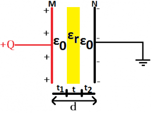
When in parallel plate capacitor, the area between the who plates are partially filled with air and partially with other substance, its Capacitance can be calculated. Let there exist a parallel plate capacitor in which medium between the parallel plates is mainly the air and partially other substance as shown in the figure below:
Multiple Parallel Plate Capacitor
The arrangement of parallel plate capacitor with dielectric material between them in groups fitting in each other is known as Multiple Parallel Plate Capacitor. The capacitance of multiple parallel plate capacitor can be calculated as:
C = [ .
.  x A / D] x (N-1)
Where A = Area of each plate;
ε0 = Relative Permittivity of a Vacuum = 8.854 × 10⁻¹² F/m;
εr = Relative Permittivity of Dielectric;
D = Distance between plates;
N = Number of Plates.
Example:
A parallel plate capacitor has initial capacity C, the permittivity of free space is εo, plate area is A, the distance between plates is d.
If the plate area increased by 4 times, the distance between plates becomes 2d and the permittivity of free space is 5εo, what is the final capacity of the parallel-plate capacitor.
Solution:
The capacity of capacitor = C
The permittivity of free space = εo
Plate area = A
The distance between plates = d
Initial capacity
C = εo . A/d
Final capacity
C = 5 εo . 4A/2d = εo . 20A/2 d = 10 εo . A/d = 10C
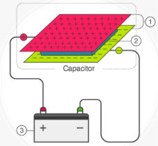
The energy stored in a capacitor is nothing but the electric potential energy and is related to the voltage and charge on the capacitor.
If the capacitance of a conductor is C, then it is initially uncharged and it acquires a potential difference V when connected to a battery.
If q is the charge on the plate at that time, then
q=CV
The work done is equal to the product of the potential and charge.
Hence, W = Vq
If the battery delivers a small amount of charge dQ at a constant potential V, then the work done is
DW=Vdq = qC dq
The total work done in delivering a charge of an amount q to the capacitor is given by
W =  dq = 1/C q2 /2 = ½ q 2 /C
Therefore, the energy stored in a capacitor is given by
U=1/2q2C
Substituting q=CV in the equation above, we get
U=1/2CV2
The energy stored in a capacitor is given by the equation U=1/2CV2.
Example:
If the capacitance of a capacitor is 50 F charged to a potential of 100 V, Calculate the energy stored in it.
Solution:
We have a capacitor of capacitance 50 F that is charged to a potential of 100 V. The energy stored in the capacitor can be calculated as follows
U=1/2CV2
Substituting the values, we get
U=1/2 50(100)2=250×103 J
Types of capacitor
There are four types of capacitors:
1. Film Capacitors:
Film Capacitors are the most normally ready of numerous types of capacitors, comprising of a generally expansive group of capacitors with the distinction being in their dielectric properties.
They are available in almost any value and voltages as high as 1500 volts. They come in any tolerance from 10% to 0.01%.
There are two types of film capacitors, radial lead type and axial lead type. The electrodes of film capacitors may be metalized aluminum or zinc, applied on one or both sides of the plastic film, resulting in metalized film capacitors called film capacitors.
The film capacitor is shown in figure below:
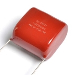 Film Capacitors
2. Ceramic Capacitors:
Ceramic capacitors are used in high frequency circuits such as audio to RF. They are also the best choice for high frequency compensation in audio circuits. These capacitors are also called as disc capacitors.
Ceramic capacitors are made by coating two sides of a small porcelain or ceramic disc with silver and are then stacked together to make a capacitor.
One can make both low capacitance and high capacitance in ceramic capacitors by changing the thickness of the ceramic disc used. The ceramic capacitor is shown in figure below:
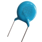 Ceramic Capacitors
3. Electrolytic Capacitors:
Electrolytic capacitors are available with working voltages up to about 500V, although the highest capacitance values are not available at high voltage and higher temperature units are available. There are two types of electrolytic capacitor, tantalum and aluminum in common.
The tantalum and aluminum capacitors are shown in figure below:
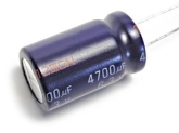 Electrolytic Capacitors
4. Variable Capacitors:
A Variable Capacitor is one whose capacitance may be intentionally and repeatedly changed mechanically. This type of capacitors utilized to set frequency of resonance in LC circuits, for instance, to adjust the radio for impedance matching in antenna tuner devices.
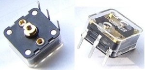
Variable Capacitors
Charging and discharging of capacitors on DC
A Capacitor is a passive device that stores energy in its Electric Field and returns energy to the circuit whenever required. A Capacitor consists of two Conducting Plates separated by an Insulating Material or Dielectric.
Figure 1 and Figure 2 are the basic structure and the schematic symbol of the Capacitor respectively.
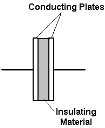
Basic structure of the Capacitor

Schematic symbol of the Capacitor
When a Capacitor is connected to a circuit with Direct Current (DC) source, two processes, which are called "charging" and "discharging" the Capacitor, happens in specific conditions.
In Figure 3, the Capacitor is connected to the DC Power Supply and Current flows through the circuit.
Both Plates get the equal and opposite charges and an increasing Potential Difference, vc, is created while the Capacitor is charging.
Once the Voltage at the terminals of the Capacitor, vc, is equal to the Power Supply Voltage, vc = V, the Capacitor is fully charged and the Current stops flowing through the circuit, the Charging Phase is over.
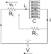
The Capacitor is Charging
A Capacitor is equivalent to an Open-Circuit to Direct Current, R = ∞, because once the Charging Phase has finished, no more Current flows through it. The Voltage vc on a Capacitor cannot change abruptly.
When the Capacitor disconnected from the Power Supply, the Capacitor is discharging through the Resistor RD and the Voltage between the Plates drops down gradually to zero, vc = 0.
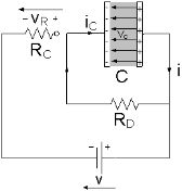
The Capacitor is Discharging
The Resistances of RC and RD affect the charging rate and the discharging rate of the Capacitor respectively.
The product of Resistance R and Capacitance C is called the Time Constant τ, which characterizes the rate of charging and discharging of a Capacitor shown in Figure.

The Voltage vc and the Current iC during the Charging Phase and Discharging Phase
References:
- Electronic Devices And Circuits Theory 10th Edition (English, Paperback, Robert L. Boylestad, Louis Nashelsky)
Electronic Principles Textbook by Albert Paul Malvino
How to Diagnose and Fix Everything Electronic, Second Edition Book by Michael Jay Geier
- Principles of Electronics is a 2002 book by Colin Simpson
Starting Electronics Book by Keith Brindley