UNIT 5
Orthographic Projection
Practical solid geometry or descriptive geometry deals with the representation of
Points, lines, planes and solids on a flat surface (such as a sheet of paper), in
Such a manner that their relative positions and true forms can be accurately determined.
Principle of projection:
If straight lines are drawn from various points on the contour of an object to meet
a plane, the object is said to be projected on that plane. The figure formed by joining, in correct sequence, the points at which these lines meet the plane, is called the projection of the object. The lines from the object to the plane are called projectors.
First angle projection:
We have assumed the object to be situated in front of the V.P. And above the H.P. i.e. in the first quadrant and then projected it on these planes. This method of projection is known as first-angle projection method. The object lies between the observer and the plane of projection. In this method, when the views are drawn in their relative positions, the top view comes below the front view. In other words, the view seen from above is placed on the other side of (i.e. below) the front view. Each projection shows the view of that surface (of the object) which is remote from the plane on which it is projected, and which is nearest to the observer.
Third angle projection:
In this method of projection, the object is assumed to be situated in the third quadrant [fig. 11(a)]. The planes of projection are assumed to be transparent. They lie between the object and the observer. When the observer views the object from the front, the rays of sight intersect the V.P. The figure formed by joining the points of intersection in correct sequence is the front view of the object. The top view is obtained in a similar manner by looking from above. When the two planes are brought in line with each other, the views will be shown in fig.11 (b). The top view in this case comes above the front view.
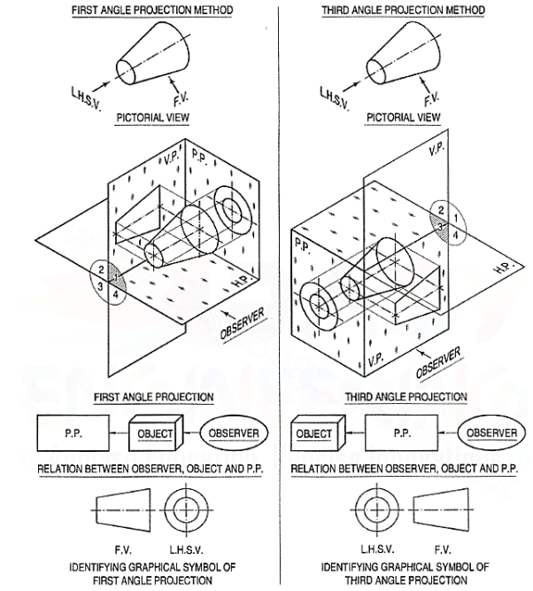
Figure 1
Six views of an Object: There are three important elements of this projection system, namely
(a) an object
(b) plane of projection
(c) an observer.
Very often, two views are not sufficient to describe an object completely. The planes of projection being imaginary, following six views are obtained:
(1) Front view
(2) Top view
(3) Left hand side view
(4) Right hand side view
(5) Back view
(6) Bottom view
These projections are shown projected on the respective planes, placed by the methods of first-angle projection and third-angle projection as shown in fig. 2.
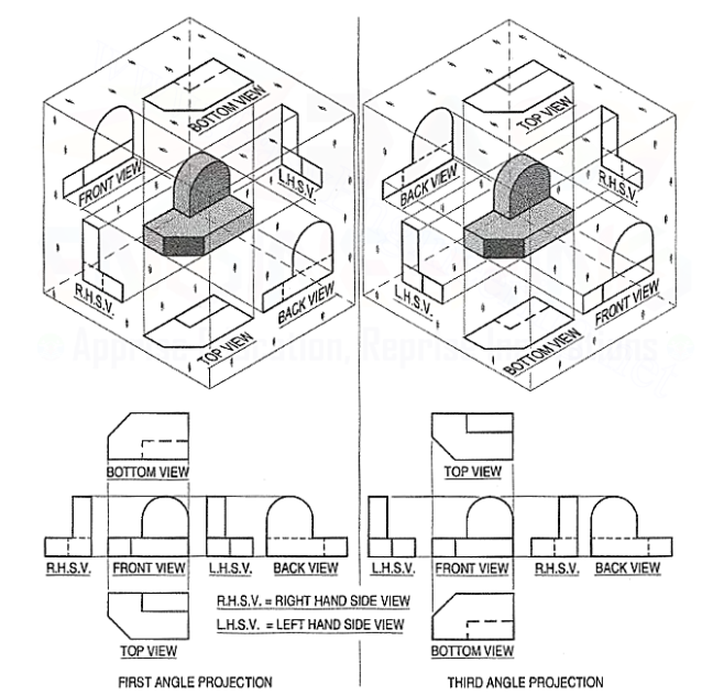
Figure 2
Problem 1. (fig. 3): AL-shaped solid object having dimensions of length width (W) and height (HJ in the fig. 3. Assuming that this object is lying in the first quadrant. Draw its front view, top view, and side view.
When the given object is in the first quadrant, its front view appears in the imaginary vertical plane V.P. Behind it while its top view appears in an imaginary horizontal plane, H.P. Below. The side view appears to the right or left of the front view depending on from which side the object is being viewed.
(i) Mark the visible corners of the given block as shown
Drawing front orthogonal view:
Assume that you are viewing the object in the direction of the arrow towards the imaginary V.P. What you will see is a rectangle of height H and width Won V.P. This will be the front view. To draw this view:
(ii) Draw a reference line xy, which represents the intersecting line of the planes V.P. And H.P. Draw a rectangle as shown W and H, above xy make sure that the width is parallel to the line xy. The rectangle is the front orthogonal view of the object.
(iii) Draw a line parallel to and thickness of h to the line 1-2. The rectangle 1-2-4-3is the front view of the horizontal L-shaped stem of the object.
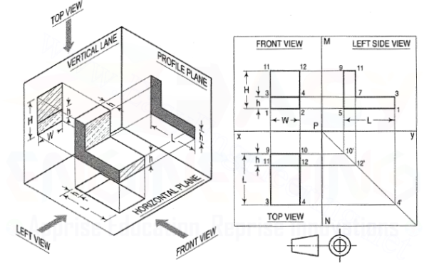
Figure 3
Drawing Top Orthogonal View:
Now, if you look the object from the top, you will see a rectangle of Length L and width W on the horizontal plane. This is the top view of plan of the object. To draw this view:
(iv) Draw vertical projectors from 1 and 2 and extend them beyond the line xy. Draw a line 9-10 below and parallel to the reference line xy. Draw the lines 9-3 and 10-4 equal to the length L of the object. Join line 3-4. The rectangle 9-10-3-4 is the top view of the object.
(v) Draw a line 11-12 parallel to and below 9-10 of thickness h. The rectangle9-11-12-10 is the view of the vertical stem of the object.
Drawing the side orthogonal view:
Now if you look at the object from the left side, what you will see is anL-shaped image having a length of Land height of Hon the auxiliary plane, AP. This view appears adjacent and to the right of front view. To draw this view:
(vi) Draw a reference vertical line MN at right angles to xy cutting it at P. From P draw a construction line at 45° in the fourth quadrant.
(vii) Project lines from the points 10, 12 and 4 of the top view to meet this inclined line at 1 O', 12' and 4'.
(viii) Project lines from points 2, 4 and 12 from the front view parallel to line xy. From points 1 O', 12' and 4' project lines vertically upwards to meet these horizontal projections.
(ix) Join points 5-1-3-7-11-9. This will be the side view of the object.
(x) Finally draw the symbol of first angle projection at the right bottom corner of the drawing.
Problem 2:
(fig. 4 and fig. 5):
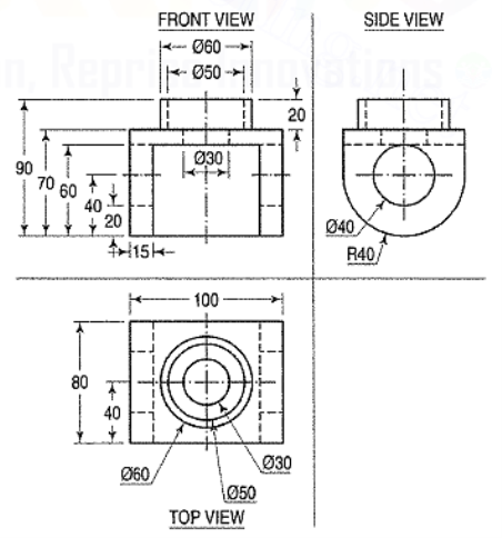
A pictorial view of a machine bracket is shown in the figure. Draw using the first angle projection method front view, top view and right end side view.
Assume that you are viewing the object in the direction of the arrow towards the imaginary V.P. What will you see? It is a rectangle of height 70 mm and width100 mm on V.P. This will be the front view. To draw this view:
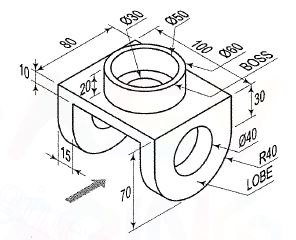
Figure 4
(i) Draw a Reference line xy, which represents the intersecting line of the planes V.P. And H.P.
(ii) Draw rectangular block of size1 00 x 70 and the thickness is 15 mm each on the two parallel portions of the slot.
(iii) Now on the top of this rectangular block draw a rectangle of size 60 mm x20 mm. This rectangle represents a boss of Φ60on the rectangular block.
(iv) Draw a hole of Φ50 in the above boss. Note carefully that the lines are dashed lines as they are invisible from the front side. The Φ30 hole is in the rectangular block.
(v) Draw the two holes on the parallel edges of the rectangular block. These holes are represented by dotted lines in the front view as they are hidden. This completes the front view construction.
(vi) To draw the top view, project all the details from front view.
(vii) Draw a vertical centre line form the centre of the rectangular block.
(viii) The top view of the rectangular block appears as a rectangle of size 100 x 80.
(ix) Draw the holes in the centre of the rectangle. These holes are drawn taking the common centre point on vertical centre line.
(x) The two holes of 040 on the lobes are not visible, so they are projected as dashed lines. This completes the top view.
(xi) To draw the side view, draw projectors from all the points in front view and top view to side view. Join the intersection points. This completes the side view.
