UNIT 2
A.C. Circuits
Sinusoidal Waveform Construction
Coil Angle ( θ ) | 0 | 45 | 90 | 135 | 180 | 225 | 270 | 315 | 360 |
e = Vmax.sinθ | 0 | 70.71 | 100 | 70.71 | 0 | -70.71 | -100 | -70.71 | -0 |
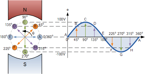
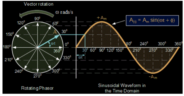
The points on the sinusoidal waveform are obtained by projecting across from the various positions of rotation between 0o and 360o to the ordinate of the waveform that corresponds to the angle, θ and when the wire loop or coil rotates one complete revolution, or 360o, one full waveform is produced.
From the plot of the sinusoidal waveform we can see that when θ is equal to 0o, 180o or 360o, the generated EMF is zero as the coil cuts the minimum amount of lines of flux. But when θ is equal to 90o and 270o the generated EMF is at its maximum value as the maximum amount of flux is cut.
Therefore a sinusoidal waveform has a positive peak at 90o and a negative peak at 270o. Positions B, D, F and H generate a value of EMF corresponding to the formula: e = Vmax.sinθ.
Then the waveform shape produced by our simple single loop generator is commonly referred to as a Sine Wave as it is said to be sinusoidal in its shape. This type of waveform is called a sine wave because it is based on the trigonometric sine function used in mathematics, ( x(t) = Amax. Sinθ )
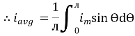
Average Value:
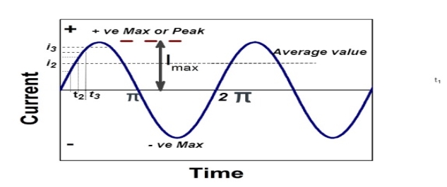
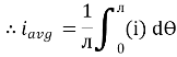
The arithmetic mean of all the value over complete one cycle is called as average value
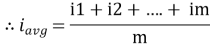
 =
= 
For the derivation we are considering only hall cycle.
Thus  varies from 0 to ᴫ
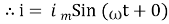
i = Im Sin
Solving
We get

Similarly, Vavg=
The average value of sinusoid ally varying alternating current is 0.636 times maximum value of alternating current.
RMS value: Root mean square value:
The RMS value of AC current is equal to the steady state DC current that required producing the same amount of heat produced by ac current provided that resistance and time for which these currents flows are identical.
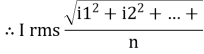
I rms = 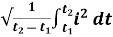
Direction for RMS value:
Instantaneous current equation is given by
i = Im Sin 
But 
I rms = 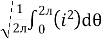
= 
=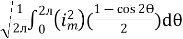
=
Solving
=
=
Similar we can derive
V rms=  or 0.707 Vm
 the RMS value of sinusoidally alternating current is 0.707 times the maximum value of alternating current
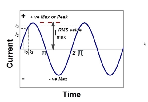
Peak value is also known as Maximum Value, Crest Value or Amplitude. It is the maximum value of alternating current or voltage from the “0” positions no matter positive or negative half cycle in a sinusoidal wave as shown in fig . It’s expressed as IM and EM or VP and IM.
Equations of Peak Voltage Value are:
VP = √2 x VRMS = 1.414 VRMS
VP = VP-P/2 = 0.5 VP-P
VP = π/2 x VAV = 1.571 x VAV
In other words, It is the value of voltage or current at the positive or the negative maximum (peaks) with respect to zero. In simple words, it is the instantaneous value with maximum intensity.
Peak to Peak Value:
The sum of positive and negative peak values is known as peak to peak value. It’s expressed as IPP or VPP.
Equations and formulas for Peak to Peak Voltage are as follow:
VP-P = 2√2 x VRMS = 2.828 x VRMS
VP-P =2 x VP
VP-P = π x VAV = 3.141 x VAV
In other words, the peak to peak value of a sine wave, is the voltage or current from positive peak to the negative peak and its value is double as compared to peak value or maximum value as shown in above figure.
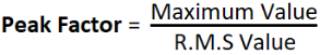
What is Peak Factor?
Peak Factor is also known as Crest Factor or Amplitude Factor.
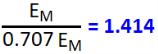
It is the ratio between maximum value and RMS value of an alternating wave
For a sinusoidal alternating voltage:
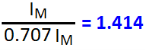
For a sinusoidal alternating current:
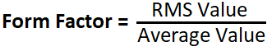
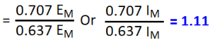
Foam factor:
The ratio between RMS value and Average value of an alternating quantity (Current or Voltage) is known as Form Factor.
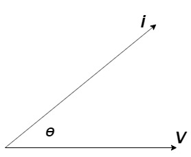
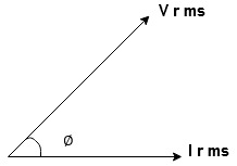
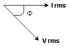
A phasor is a vector that is used to represent a sinusoidal function. It rotates about the origin with an angular speed ω.
The vertical component of phasors represents the quantities that are sinusoidally varying for a given equation, such as v and i. Here, the magnitude of the phasors represents the peak value of the voltage and the current.
From the figure shown above, we can see the relation between a phasor and the sinusoidal representation of the function with respect to time. The projection of the phasor on the vertical axis represents the value of the quantity.
For example, in the case of a current or a vector phasor, the projection of the phasor on the vertical axis, given by vmsinωt and imsinωt respectively, gives the value of the current or the voltage at that instant.
From the phasor diagram, it is easy to detect that one of two quantities are in the same phase. For example, if for a given circuit, the phasors for the voltage and the current are in the same direction for all instances, the phase angle between the voltage and the current is zero.
Reactance :
- Inductive Reactance (XL)
It is opposition to the flow of an AC current offered by inductor.
XL = ω L But ω = 2 ᴫ F
 XL = 2 ᴫ F L
It is measured in ohm
 XL∝FInductor blocks AC supply and passes dc supply zero
2. Capacitive Reactance (Xc)
It is opposition to the flow of ac current offered by capacitor
Xc = 
Measured in ohm
 Capacitor offers infinite opposition to dc supply
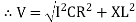
Impedance (Z):
The ac circuit is to always pure R pure L and pure C it well attains the combination of these elements. “The combination of R1 XL and XC is defined and called as impedance represented as
Z = R +i X
Ø = 0
 Only magnitude
R = Resistance, i = denoted complex variable, X =Reactance XL or Xc
Polar Form
Z =  L I
L I
Where  =
=
 Measured in ohm
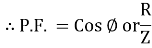
Power factor (P.F.):
It is the cosine of angle between voltage and current
If Ɵis –ve or lagging (I lags V) then lagging P.F.
If Ɵ is +ve or leading (I leads V) then leading P.F.
If Ɵ is 0 or in phase (I and V in phase) then unity P.F.
Ac circuit containing pure resisting:
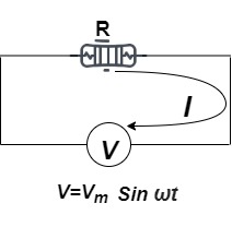
Consider Circuit Consisting pure resistance connected across ac voltage source
V = Vm Sin ωt①
According to ohm’s law i =  =
= 
But Im = 
 ②
②
Phase’s diagram
From ① and ② phase or represents RMD value.
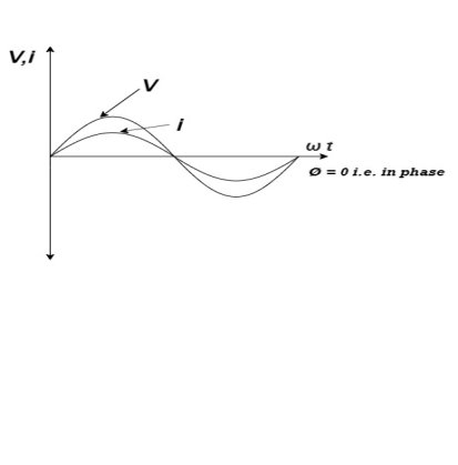
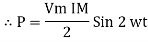
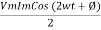
Power P = V. i
Equation P = Vm sin ω t Im sin ω t
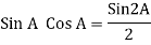
P = VmIm Sin2 ω t
P =  -
- 

Constant fluctuating power if we integrate it becomes zero

Average power
Pavg = 
Pavg = 
Pavg = Vrms Irms
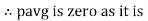
Power ware form [Resultant] :
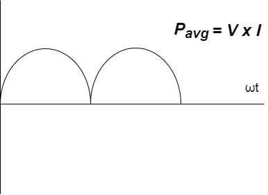
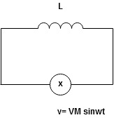
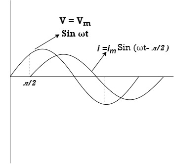
Ac circuit containing pure Inductors:
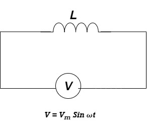
Consider pure Inductor (L) is connected across alternating voltage. Source
V = Vm Sin ωt
When an alternating current flows through inductance it set ups alternating magnetic flux around the inductor.
This changing the flux links the coil and self-induced emf is produced
According to faradays Law of E M I
e = 
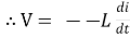
At all instant applied voltage V is equal and opposite of self-induced emf [Lenz’s law]
V = -e
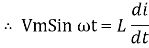
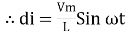
 =
= 
But V = Vm Sin ωt
 dt
dt
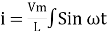
Taking integrating on both sides
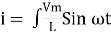 dt
dt
 dt
dt
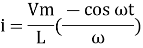
 (-cos
(-cos  )
)
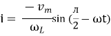
But sin (– ) = sin (+
 )
)
 sin (
sin ( -
-  /2)
/2)
And Im= 
 /2)
/2)
 /2
/2
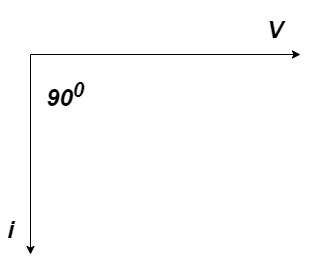
= -ve
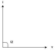
= lagging
= I lag v by 900
Waveform:

Phasor:
Power P = Ѵ. I
= Vm sin wtIm sin (wt /2)
/2)
= VmIm Sin wt Sin (wt –  /s)
/s)
 ①
①
And
Sin (wt -  /s) = - cos wt ②
Sin (wt –  ) = - cos
 sin 2 wt from ① and ②
The average value of sin curve over a complete cycle is always zero
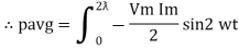
 Pavg = 0
Ac circuit containing pure capacitors:
Consider pure capacitor C is connected across alternating voltage source
Ѵ = Ѵm Sin wt
Current is passing through capacitor the instantaneous charge ɡ produced on the plate of capacitor
ɡ = C Ѵ
ɡ = c Vm sin wt
The current is rate of flow of charge

i= (cvm sin wt)
i = c Vm w cos wt
Then rearranging the above eqth.
i =  cos wt

 = sin (wt +
  X/2)
X/2)
i =  sin (wt + X/2)
But 
 X/2)
X/2)

= leading
= I lead V by 900
Wave form:
Phase:
Power P= Ѵ. i
= [Vmsinwt] [ Im sin (wt + X/2)]
= VmIm Sin wt Sin (wt + X/2)]
 (cos wt)
 to charging power waveform [resultant].
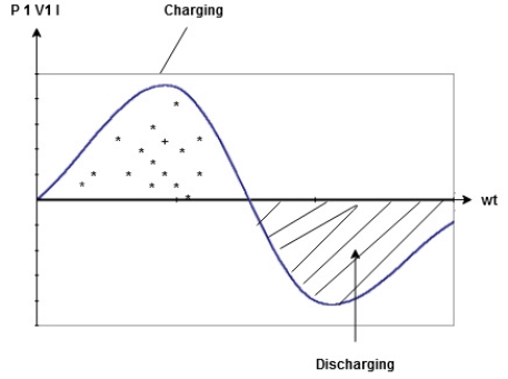
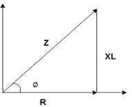
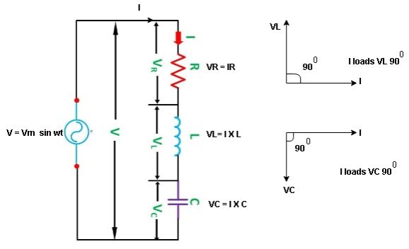
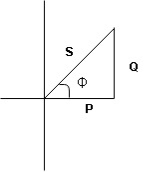
Series R-L Circuit:
Consider a series R-L circuit connected across voltage source V= Vm sin wt
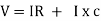
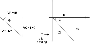
As some I is the current flowing through the resistor and inductor due do this current voltage drops arcos R and L R  VR = IR and L
  VL = I X L
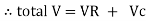
 Total V = VR + VL
V = IR + I X L  V = I [R + X L]


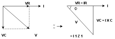
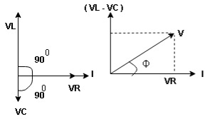
Take current as the reference phasor : 1) for resistor current is in phase with voltage 2) for Inductor voltage leads current or current lags voltage by 90 0.
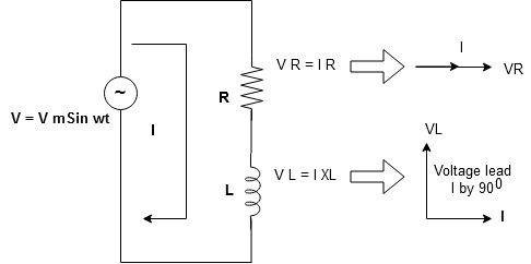
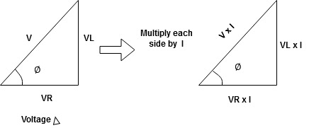
For voltage triangle:
Ø is power factor angle between current and resultant voltage V and
V = 
V = 

Where Z = Impedance of circuit and its value is  =
= 
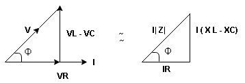
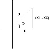
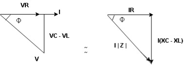
Impedance Triangle :
Divide voltage triangle by I
Rectangular form of Z = R+ixL
And polar from of Z =  L +
L + 
(+ j X L +  because it is in first quadrant )
Where  =
= 
 + Tan -1
Current Equation :
From the voltage triangle we can sec. That voltage is leading current by  or current is legging resultant voltage by
Or i =  =
=  [ current angles - Ø )
Resultant Phasor Diagram from Voltage and current eqth.
Wave form :

Power equation :
P = V .I.
P = Vm Sin wtIm Sin wt – Ø
P = VmIm (Sin wt) Sin (wt – Ø)
P =  (Cos Ø) - Cos (2wt – Ø)
Since 2 sin A Sin B = Cos (A-B) – Cos (A+B)
P =  Cos Ø -
  Cos (2wt – Ø)

①②
Average Power:
Pang =  Cos Ø
Cos Ø
Since ② term become zero because Integration of cosine come from 0 to 2ƛ
 pang = Vrms Irms cos Ø watts.
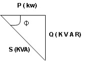
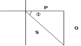
Power Triangle :
From 
VI = VRI + VLI B
Now cos Ø in  A =
A = 
 ①
①
Similarly Sin  =
= 


Apparent Power Average or true Reactive or useless power
Or real or active
-Unit (VI) Unit (Watts) C/W (VAR) denoted by (Ø)
Denoted by [S] denoted by [P]
Power  for R L ckt:

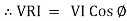
Series R-C circuit :
V = Vm sin wt
VR

 I
I
- Consider a series R – C circuit in which resistor R is connected in series with capacitor C across an ac voltage so use V = VM Sin wt (voltage equation).
- Assume Current I is flowing through
R and C  voltage drops across.
R and C  R
R  VR = IR
And C  Vc = I
 c
c

 V =
V =  lZl
lZl
Voltage triangle:
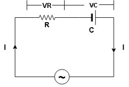
It take current as the reference phasor 1) for resistor current is in phase with voltage 2) for capacitor current leads voltage or voltage lags behind current by 900
Where Ø is power factor angle between current and voltage (resultant) V
And from voltage
V = 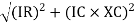
V = 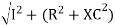
V = 
V =  lZl
lZl
Where Z = impedance of circuit and its value is lZl = 
Impendence triangle:
Divide voltage  by
by  as shown
Rectangular from of Z = R - jXc
Polar from of Z = lZl L - Ø
( - Ø and –jXc because it is in fourth quadrant ) where
LZl = 
And Ø = tan -1 
Current equation:
From voltage triangle we can see that voltage is lagging current by Ø or current is leading voltage by Ø
 i = IM Sin (wt + Ø) since Ø is +ve
Or i =  for RC
 LØ [ resultant current angle is + Ø]
Resultant phasor diagram from voltage and current equation :
Resultant wave form:

Power Equation:
P = V. I
P = Vm sin wt. Im Sin (wt + Ø)
= VmIm sin wt sin (wt + Ø)
2 Sin A Sin B = Cos (A-B) – Cos (A+B)
 -
- 
Average power:
Pang =  Cos Ø
Cos Ø
Since 2 terms integration of cosine wave from 0 to 2ƛ become zero
 2 terms become zero
 pang = Vrms Irms Cos Ø
Power triangle RC Circuit:
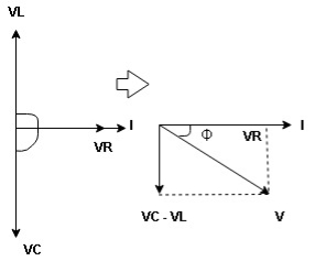
R-L-C series circuit:
Consider ac voltage source V = Vm sin wt connected across combination of R L and C. When I flowing in the circuit voltage drops across each component as shown below.
VR = IR, VL = I  L, VC = I
  C
C
- According to the values of Inductive and Capacitive Reactance I e XL and XC decides the behaviour of R-L-C series circuit according to following conditions
① XL> XC, ② XC> XL, ③ XL = XC
① XL > XC: Since we have assumed XL> XC
 Voltage drop across XL> than XC
 VL> VC A
- Voltage triangle considering condition A

VL and VC are 180 0 out of phase .
Therefore cancel out each other
 Resultant voltage triangle
Now V = VR + VL + VC c phasor sum and VL and VC are directly in phase opposition and VL
 VC
VC their resultant is (VL - VC).
From voltage triangle
V = 
 V =
V = 
 V = I
V = I 

Impendence  : divide voltage
Rectangular form Z = R + j (XL – XC)
Polar form Z =  l + Ø B
Where  =
= 
And Ø = tan-1 
- Voltage equation : V = Vm Sin wt
- Current equation
i =  from B
i =  L-Ø C
L-Ø C
As VL VC the circuit is mostly inductive and
  I lag behind V by angle Ø
 Since i =
  L-Ø
L-Ø
 i = Im Sin (wt – Ø) from c
- XC
 XL :Since we have assured XC
  XL
XL
 the voltage drops across XC
  than XL
 XC
XC  XL (A)
 voltage triangle considering condition (A)
 Resultant Voltage
Now V = VR + VL + VC  phases sum and VL and VC are directly in phase opposition and VC
 VL
VL  their resultant is (VC – VL)
From voltage 
V = 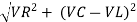
V = 
 V =
V = 
 V =
V = 

 Impedance
  : Divide voltage
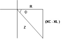
- Rectangular form : Z + R – j (XC – XL) – 4thqurd
Polar form : Z =  L -
L -
Where 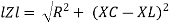
And Ø = tan-1 – 
- Voltage equation : V = Vm Sin wt
- Current equation : i =
 from B
 - i =
 L+Ø C
L+Ø C
As VC  the circuit is mostly capacitive and
  leads voltage by angle Ø
Since i =  L + Ø
L + Ø
 Sin (wt – Ø) from C
- Power
 :
:
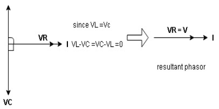
- XL= XC (resonance condition):
ɡȴ XL= XC then VL= VC and they are 1800 out of phase with each other  they will cancel out each other and their resultant will have zero value.
Hence resultant V = VR and it will be in phase with I as shown in below phasor diagram.
From above resultant phasor diagram
V =VR + IR
Or V = I  lZl
lZl
Because lZl + R
Thus Impedance Z is purely resistive for XL = XCand circuit current will be in phase with source voltage.

 Since VR=V Øis zero when XL = XC
  power is unity
i.e pang = VrmsI rms cos Ø = 1 cos o = 1
Maximum power will be transferred by condition. XL = XC
Series and parallel resonance
Resonance in series RLC circuits:
Definition: it is defined as the phenomenon which takes place in the series or parallel R-L-C circuit which leads to unity power factor
Voltage and current in R – L - C ckt. Are in phase with each other
Resonance is used in many communicate circuit such as radio receiver.
Resonance in series RLC series resonance in parallel RLC anti resonance / parallel resonance.
- Condition for resonance XL = XC
- Resonantfrequency (Fr) : for given values of R-L-C the inductive reactance XL become exactly equal to the capacitive reactance Xc only at one particular frequency. This frequency is called as resonant frequency and denoted by (fr)
- Expression for resonant frequency(fr) : we know that XL = 2ƛ FL - Inductive reactance
Xc =  - capacitive reactance
At a particular frequency ȴ = fr, the Inductive and capacitive reactance are exactly equal
 XL = XC ……at ȴ = fr
I.e. L =
L = 
 fr2 =
fr2 = 
 fr =
fr =  H2
H2
And  = wr =
  rad/sec


