UNIT – 4
General System of Forces
In general, it can be said that resulting of any number of concurrent forces in a plane is given by the closing side of the polygon of forces obtained by successive geometric addition of their free vectors.
In a particular case where the end of the last vector coincides with beginning of first vector, the resultant vanishes and the system is in equilibrium.
"This states that, whenever a system of coplanar concurrent forces are in equilibrium, the force polygon formed by their free vectors result in a closed polygon."
Three methods exist to find the unknown force or its direction in a given system of coplanar concurrent forces that is in equilibrium:
1. Lami's Theorem:
"If three concurrent forces acting on a body, kept in an equilibrium, then each force is proportional to the sine of the angle between the other two forces and the constant of proportionality is same.
A/sin(α)= B/sin(β) =C/sin(γ)....... (Sine rule)
Note: While applying this theorem, in FBD of the body, draw the directions of forces either directed towards or away from the point of concurrency.
2. Method of Projections:
Involves resolution of each force in to its rectangular components along X and Y axis.
Solve the following equations -
∑(Fx)i = 0 ; ∑(Fy)i = 0 ---
Sum of all X components of forces =0 and Sum of all Y components of forces = 0
3. Method of Moments:
Algebraic sum of moments of a system of concurrent forces in a plane become equal to zero abot two different points (moment centres) on the plane which are not on a straight line with the point of concurrency of the force system -
∑(Mb)i = 0 ; ∑(Mc)i = 0
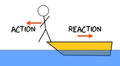
Newton’s Third Law of Motion states, “When one object exerts a force on a second object, the second one exerts a force on the first that is equal in magnitude and opposite in direction.”
This law is sometimes called the “Law of Action and Reaction”.
Even though the forces are equal in magnitude (strength) and opposite in direction, they do not cancel each other. This law addresses two objects, each with only one force exerted on it.
Each object is exerting one force on the other object.
Each object is experiencing only one force.
- The action and reaction forces are reciprocal (opposite) on an object.
- Examples may include:
- A swimmer swimming forward:
- The swimmer pushes against the water (action force), the water pushes back on the swimmer (reaction force) and pushes her forward.
- A ball is thrown against a wall:
- The ball puts a force on the wall (action force), and the wall puts a force on the ball (reaction force) so the ball bounces off.
- A person is diving off a raft:
- The person puts a force on the raft (action force) pushing it, and the raft puts a force on the diver (reaction force) pushing them in the opposite direction.
- A person pushes against a wall (action force), and the wall exerts an equal and opposite force against the person (reaction force).
- The Space Shuttle engines push out hot gases (action force), and the hot gases put a force on the shuttle engines (reaction force) so the shuttle lifts (there is no sling shot doing it!)
Types of Support
- Roller Support: -
 Roller support is show in two ways as shown:
 A free body diagram of roller support is shown in figure given below
- Roller support offers only one reaction; which is always perpendicular to the base or plane of roller.
- All the steel trusses of the bridges have one of their ends supported on roller.
- Main advantages of the support are that beam can easily move towards left or right due to expansion & contraction.
2. Hinge support

- In this case, end of the beam is hinged to the support as shown in figure above.
- This type of support offers two reactions, one is parallel to base and perpendicular to the base
- All the steel trusses of the bridges have one of their end roller supported & other end is hinged
- Main advantage of this support is that beam remains stable.
- If both ends of the beam are roller supported, then beam can not be stable. Thus, one support of beam is made roller supported and other is hinged.
3. Internal Hinge: -
When two members are connected by the hinge then this type of support is called as internal Hinge.


Internal Hinge
Reactions at internal Hinge
4. Fixed support: -
Fixed support offers three reactions as shown in figure below.
- Reaction in horizontal direction.
- Reaction in vertical direction.
- Moment (fixing moment)

Fixed Support
Type of supports and reaction
- Point load
Load acting at a single point on the beam is known as point load. Its unit is N or kN

2. Uniformly Distributed load (UDL) or Rectangular Load:
A load which is spread over the beam or part of the beam uniformly is known as UDL
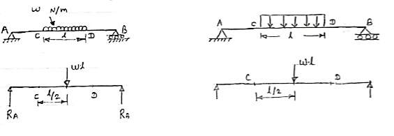
Conversion of UDL or Rectangular load into point load
= Intensity of UDL × distance
= w. l. ------------- N
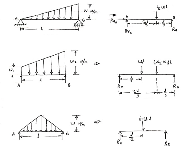
3. Uniformly varying load or Triangular load:
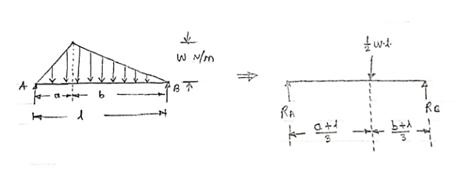
A load whose intensity is linearly varying between the two points on the beam is known as UVL. If an intensity of the load at one end is zero and at other ends is maximum then it is called as uniformly varying load or triangular load.
Following figures shows different types of UVL
- To convert UVL into point load, calculate the area of uniformly varying load.
- For location of point load find x coordinate of centroid of the UVL area.
3.
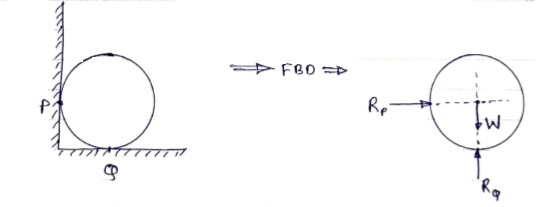
If a body is shown with all external forces acting on it so that the body is in equilibrium, such diagram is called as free body diagram.
To draw the free body diagram, we have to remove all the restrictions like wall, floor, hinge, any other support and replace them by reactions which these support extents on the body.
Ex – 1) Draw FBD of a bar supported and loaded as shown below.

2) Draw FBD of sphere supported as shown below.
Lami’s Theorem: - (Body is subjected to three forces)
If three coplanar concurrent forces are in equilibrium then, the ratio of magnitude of any force to the sine of angle between the other two is constant.
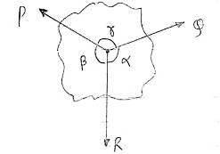
According to Lami’s Theorem:
Lami’s theorem can also be written as:If three coplanar concurrent forces acting at a point are in equilibrium, each force is proportional to the sine of angle between other two.
Body subjected to two forces:

P=Q, body is in equilibrium P=Q, but body is not in equilibrium
If an object is subjected to forces acting at two points, then body will be in
Equilibrium only when those two forces are equal & opposite.
Problems in two and three dimensions:
The above-mentioned procedure (2.2) is used for finding solutions to two- and three-dimensional problems. This procedure can be better understood through some of the examples mentioned below.
Problems in Two-dimensions:
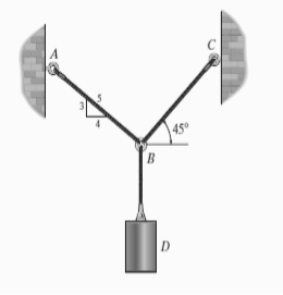
e.g. 1: Determine the tension that will be there in cables BA and BC necessary to support the 60-kg cylinder in Fig. Below.
Solution:
The first step involves drawing the free-body diagram of the given example. As this is two-dimensional structure, we will follow the method mentioned for two-dimensional coplanar structure.
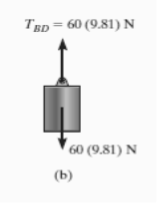
- Free-Body Diagram. Due to equilibrium, the weight of the cylinder sources the tension in cable TBD = 60*(9.81), Fig. (b). Using the equilibrium at B, forces in BA and BC can be found out. The free-body diagram is shown in Fig. Below (c). The magnitudes of TA and TC are unknown, but their directions are known.
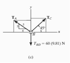
2. Equations of Equilibrium: Applying the equations of equilibrium along the x and y axes, we have
Σ Fx = 0 i.e. TC cos 45° - (4/5)TA = 0
Σ Fy = 0 i.e. TC sin 45° + (3/5)TA - 60(9.81) N = 0
Solving the above equations, we get, TC = 475.66 N = 476 N
Then, substituting this value in above equation,
TA = 420 N
In this way, using the equilibrium equations, we can solve for the unknown force in the given problem.
e.g. 2: The 200-kg crate in Fig. Below is suspended using the ropes AB and AC . Each rope can withstand a maximum force of 10 kN before it breaks. If AB always remains horizontal, determine the smallest angle to which the crate can be suspended before one of the ropes breaks.
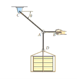
Solution:
Free-Body Diagram: We will initially understand the equilibrium of ring. There are three forces acting on it, as shown in fig. (b). The magnitude of is equal to the weight of the crate, i.e.,
FD = 200 (9.81) N = 1962 N < 10 kN
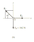
Equations of Equilibrium: Applying the equations of equilibrium along the x and y axes,
Σ Fx = 0
i.e. - FC cos θ + FB = 0
Therefore FC = ( FB / cos θ )
Σ Fy = 0
i.e. FC sin θ - 1962 N = 0
As seen from the above equations, FC is always greater than FB as cos θ is less than or equal to 1. So, rope AC will reach the max value of tensile force of 10 kN before that of rope AB. Thus, substituting FC = 10 kN in the above equations, we get
[10(103) N] sin θ - 1962 N = 0
Thus, θ = 11.30
The force developed in rope AB can be obtained by substituting the values for θ and FC into Equations mentioned above.
We get, FB = 9.81 kN.
In this way, using equations of equilibrium and free-body diagrams, we can calculate unknown quantities of the given problem.
Problems in Three-dimensions:
e.g. 3: The 10-kg lamp in Fig. Below is suspended from the three equal-length cords. Find the smallest vertical distance s from the ceiling if force built in cord is not to go beyond 50 kN.
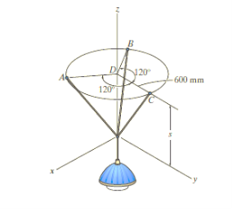
Solution:
For solving these three-dimensional numerical, we will follow the same procedure mentioned above.
Free-Body Diagram: Because of symmetry, the distance are as  mm. It follows that from Σ Fx = 0 and Σ Fy = 0, the tension T in each cord will be the same. Also, the angle between z axis and every cord is
  .
.
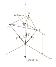
Equation of Equilibrium: Applying the equilibrium equation along the z-axis, with T = 50 N, we have
Σ Fz = 0;
3[(50 N) cos  ] - 10(9.81) N = 0
 = cos-1 (98.1 / 150)
= 49.160
Now,
By geometry shown in free-body diagram,
Tan 49.160 = (600 / s)
s = 519 mm
In this way, three-dimensional problems are solved using equations of equilibrium.
e.g. 4: A 90-lb load is being suspended from a hook as shown in Fig. Below. If the load is being supported by two cables and a spring having a stiffness of k = 500 lb/ft, find the force in the cables and the stretch of the spring for equilibrium. Cable AD lies in the x–y plane and cable AC lies in the x–z plane.
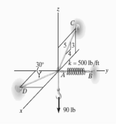
Solution:
Initially, force in spring is determined to determine stretching of spring.
Free-Body Diagram. A point is choosen for all analysis as all the points are concurrent here. The free-body diagram for the problem is shown in Fig. Below.
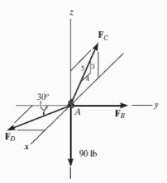
Equations of Equilibrium. We can resolve each force in x, y and z components, and so we can use three scalar equations of equilibrium. Considering components directed along each positive axis as “positive,” we have
Σ Fx = 0
FD sin 30° - (4/5) FC = 0
Σ Fy = 0
-FD cos 30° + FB = 0
Σ Fz = 0
(3/5) FC – 90 lb = 0
Thus, solving the above-mentioned equations, we get,
FC = 150 lb
FD = 240 lb
FB = 207.8 lb
The stretch of the spring is therefore
FB = ksAB
207.8 lb = (500 lb/ft) (sAB)
sAB = 0.416 ft
Thus, the method discussed earlier can be followed as shown in the examples for finding out the unknown quantities in two- and three-dimensional problems using equations of equilibrium.
Moment:-
The turning effect produced by a force on the body on which it acts is called as Moment.
Moment of force about any point is the product of magnitude of force and perpendicular distance of force from the point about which moment is to be taken.
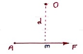
Let force F is applied at point A as shown & O is any point about which we want to take moment.
Thus from point O, draw OM line perpendicular to the line of action of force.
OM = d = Perpendicular distance between Force & point O.
Moment = M = F x d
Graphical representation of Moment:-
- Select suitable scale to locate the force graphically.
- Draw a line parallel to line of action of force. Length of this line can be calculated from selected scale.
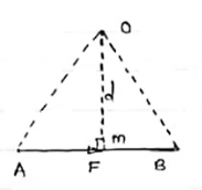 - Length of a line will be equal to magnitude of force.In the figure, Force F is represented by line AB.
- Now let O is the moment centre &
OM = d = perpendicular distance
By definition, Mo = F xd
Now join OA & OB, then
In Δ OAB
Area (ΔOAB) = ½ x AB x OM
2 (Area of ΔOAB) = F xd = Mo
Thus the moment of any force about any point is numerically equal to twice area of triangle in which base represents force & height represents the perpendicular distance.
Varignon Theorem [Law of Moments] :-
It states that if number of forces is acting simultaneously on a body, the algebraic sum of moments of all the forces about any point is equal to moment of their resultant about same point.
Mathematically,
∑(F xd) = (R x X)
Where, F = All forces acting on a body
d = ḻlar distance
R = Resultant of all forces
X = ḻlar distance of Resultant force about a point where moment is taken.
Use:- This theorem is useful to calculate or find the position or location of Resultant of non-concurrent force system.
1. If the body moves in any direction, it means that there is a resultant force acting on it. In other words, the horizontal component of all the forces (Σ H) and vertical component of all the forces (ΣV) must be zero. Mathematically,
Σ H = 0 and Σ V = 0
2. If there is rotation of body, without moving, that means there is couple acting. In other words, the resultant moment of all the forces (Σ M) must be zero. Mathematically,
Σ M = 0
3. If the body moves in any direction and at the same time it rotates about itself, if means that there is a resultant force and also a resultant couple acting on it. In other words, horizontal component of all the forces (Σ H), vertical component of all the forces (Σ V) and resultant moment of all the forces (Σ M) must be zero. Mathematically,
Σ H = 0 Σ V = 0 and Σ M = 0
4. If the body is completely at rest it means there is no force nor any couple acting on it. A little consideration will show, that in this case the following conditions are already satisfied:
Σ H = 0 Σ V = 0 and Σ M = 0
The above-mentioned equations are known as the conditions/equations of equilibrium.
Thus, the equations of equilibrium for two-dimensional coplanar force system are given by considering that the particle is present in x-y plane as shown in fig. Below, then the force can be resolved into i and j components.
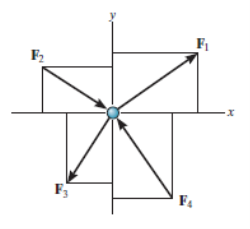
For equilibrium, the forces must add on to produce a zero-force output, i.e.,
Σ F = 0
Σ Fx i + Σ Fy j = 0
Thus, for satisfying this vector equation, the x and y component must be zero as mentioned in earlier points. Hence,
Σ Fx = 0
Σ Fy = 0
Thus, for solving two-dimensional coplanar force problems using conditions of equilibrium, we can follow the below-mentioned procedure.
Free-Body Diagram.
• In any orientation, establish x and y axes.
• Then mark all the known and unknown forces in figure.
• Unknown forces are also assumed and plotted.
Equilibrium equation.
• Apply the equations of equilibrium, Σ Fx = 0 and Σ Fy = 0.
• The forces are directed as positive for those along positive axis and vice-versa.
• If the resultant comes out to be negative value, it means that the direction needs to be reversed for that is already considered.
As we know, the sufficient case for stating equilibrium for a body under combination of forces is Σ F = 0.
For any three-dimensional force system, as shown in Fig. Below, we can resolve the forces into their respective i, j, k components, so that
Σ Fx i + Σ Fy j + Σ Fz k = 0
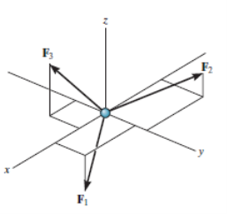
To satisfy this equation we require,
Σ Fx = 0
Σ Fy = 0
Σ Fz = 0
These three equations state that the algebraic sum of the components of all the forces acting on the particle along each of the coordinate axes must be zero. Using these equations mentioned we can solve for maximum three of the unknowns, shown by coordinate direction angles or magnitudes of forces shown on the particle’s free-body diagram.
For solving three dimensional problem we can use the following procedure.
Free Body Diagram:
• In any orientation, establish x and y axes.
• Then mark all the known and unknown forces in figure.
• Unknown forces are also assumed and plotted.
Equations of Equilibrium.
• Apply the equations of equilibrium, Σ Fx = 0, Σ Fy = 0 and Σ Fz = 0.
• Initially we can display as a Cartesian vector if it becomes to solve the problem regularly , substitute these vectors into Σ F = 0 and then set the i, j, k components equal to zero.
• If the resultant comes out to be negative value, it means that the direction needs to be reversed for that is already considered.