UNIT –5
Analysis of Plane Trusses
Trusses are simply defined as triangulation of members to make the stabilized structure. Triangulation is the stable configuration mathematically. Generally, a truss has the members called as top chord, bottom chord, vertical chord and diagonal chord. The main functions of the trusses are:
- Carrying the loads from the over structures
- Providing adequate lateral stability to the entire structure
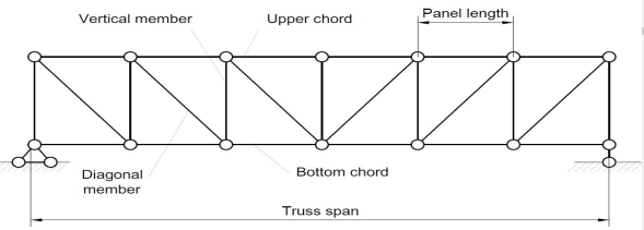
There are some basic assumptions in the designing process. It should be clarified that the construction of the trusses should conform with the design assumptions to avoid the unwanted failures due to the dispersion of the forces and loads. Following are the assumptions in truss design.
- Truss members will carry only the axial forces
- The nodes i.e the connections of the members are designed as pinned joints so that moments won’t be transferred to the members of the truss
- All the external loads and the reactions are act only on the nodes
- Generally, the truss should be in a plane.
Typically the members of the trusses are made as I sections, angles, T sections, Tube sections, Square sections and channel sections. I sections are more preferable as a optimized section in terms of the structural forces.
TYPES OF TRUSSES
- Simple truss – indicates a single triangular truss. These trusses are most often used as the roof trusses.
- Planar truss – as the name implies it is a two dimensional truss. If all the members and the nodes are in a planar surface, then this truss is a planar truss.
- Space frame truss – Contrast to planar truss, the members and the nodes are located in the three dimensional space. Electrical and telecom towers are the one of the simplest example that we are seeing in the day to day life.
FORMS OF TRUSSES
1. Pratt truss
 Pratt truss form for the loads in gravity direction
 Pratt truss form for the uplift loads(loads opposite to gravity)
2. Warren truss

3. North light truss

4. Vierendeel truss

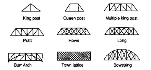
King post truss, Bowstring truss, Queen post truss, Flat truss, Lenticular truss are some other forms of trusses in the use of the industry.
Truss:-
A Rigid structure formed by connecting various two force members to each other by using pin joint..
Plane truss: When all member of the truss lies in one plane, Then truss is known as plane truss
Rigid truss:- A truss which do not collapse when external Load is applied on it.
Simple truss:-The structure formed by basic triangle made by Connecting various members are called simple truss
Classification of Truss:-
Perfect truss Imperfect (unstable)
(Stable) (n  2j R)
2j R)
(n=2j- R) over stable Deficient
Truss,
(Redundant)
(n< 2 j – R) (n < 2 j-R)
- Perfect truss :
A truss which does not collaspe under the action of
Load is called perfect truss.
Condition : n = 2 j-R
n= no. Of member 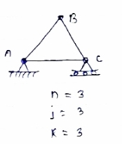
j = no of joints
R = no. Of reaction
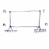
In truss ABC, n = 3 & 2 j- R+3
So it is perfect truss
- Imperfect truss: A truss which does not collapse under the load is called
Imperfect or unstable truss.
Here n 2j -R
2j -R
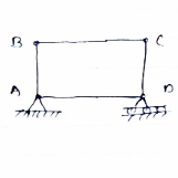
Over stable (Redundant Truss)
A truss in which n > 2j- R, Then it is over stable truss.
Diagram


Deficient truss
It is a trusses in which
N <2 j-R.
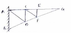
- Cantilever Truss:
A truss which is fixed on one side & free of Other end is called as cantilever truss.
.
Diagram
*Assumption made in the analysis:-
1) Given truss a perfect truss
2) The truss member are connected by joints only.
3) External loads are acting at the joints only.
4) All members are two force members.
5) The self- weight of members is neglected.
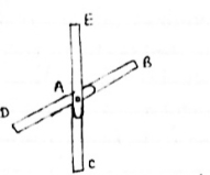
1) If
When four members are connected
At Engile joint in such a way
That opposite members lie in a
Single straight line
&
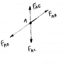
There is No external load acting at the joint Then Forces in the opposite members Are equal.
FAE = FAC & FAB = FAD.
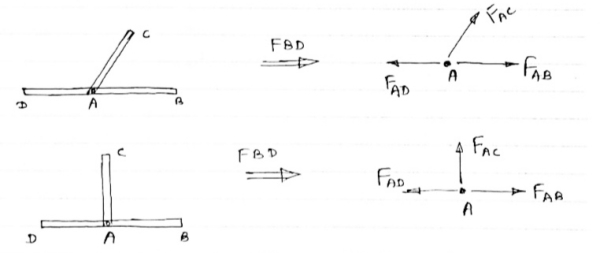
2) If There are only there members at a joint and Out of there, two are collinear and is inclined To first two or lar to first members, With no external load at joint,
Then,
a) Forces in the two opposite ( co- linear) members are equal.
l.e FAD = FAB
b) The force in the inclined member is zero
l.e FAC =0
c) Force in the perpendicular member is zero
FAc = 0
4) If There are two member at a joint with one Member Horzintal & one vertical & there is no external load of joint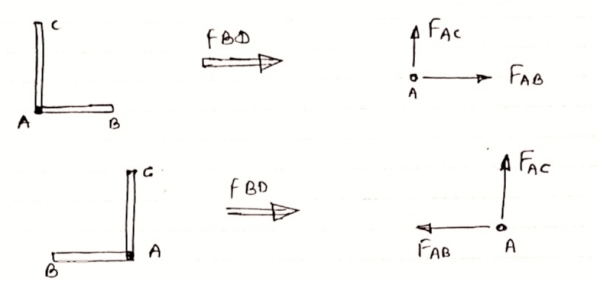
Then, Both member are zero force member,
Angle FAB=0
FAC =0
5) If there are only two members at joint With- one member vertical & other inclined & there is no external load of joint,

Then Both members are zero force members
i.e FAB = 0 & FAC =0
One member Horizontal & other inclined and There is No external load at joint.

Then Both members are zero force members
FAB = 0 and FAC =0
6 ) if t here are only two members at a joint with one member Horizontal & other inclined and there is no External load at joint
Diagram

Then both members are zero force member
FAB=0 and FAC = 0
A truss is a structure composed of straight, slender members connected at their ends by frictionless pins or hinges. A truss can be categorized as simple, compound, or complex. A simple truss is one constructed by first arranging three slender members to form a base triangular cell. Additional joints can be formed in the truss by subsequently adding two members at a time to the base cell, as shown in Figure 2.3 a. A compound truss consists of two or more simple trusses joined together, as shown in Figure 2.3 b. A complex truss is neither simple nor compound, as shown in Figure 2.3 c; its analysis is more rigorous than those of the previously stated trusses.
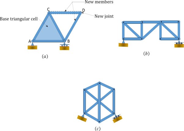
Fig. 2.3. Classification of trusses.
Types of Trusses
The following are examples of different types of trusses for bridges and roofs.
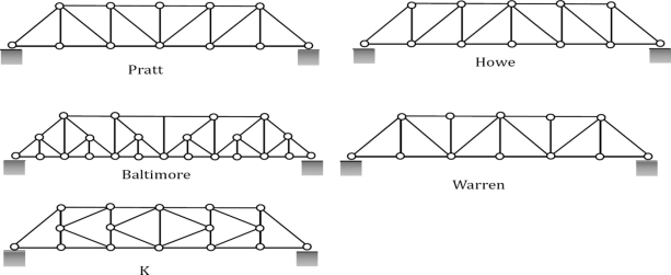
Fig. 2.3(A). Commonly used bridge trusses.
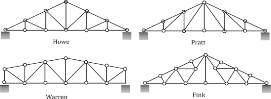
Fig. 2.3(B). Commonly used roof trusses.
2.3 Determinacy and Stability of Trusses
The conditions of determinacy, indeterminacy, and instability of trusses can be stated as follows:

Where
m = number of members.
r = number of support reactions.
j = number of joints.
Assumptions in Truss Analysis
1. Members are connected at their ends by frictionless pins.
2. Members are straight and, therefore, are subjected only to axial forces.
3. Members’ deformation under loads are negligible and of insignificant magnitude to cause appreciable changes in the geometry of the structure.
4. Loads are applied only at the joints due to the arrangement of members.
Joint Identification and Member Force Notation
Truss joints can be identified using alphabets or numbers, depending on the preference of the analyst. However, consistency must be maintained in the chosen way of identification to avoid confusion during analysis. A bar force can be represented by any letter (F or N or S), with two subscripts designating the member. For example, the member force FAB in the truss shown in Figure is the force in the member connecting joints A and B.

Fig. 2.3(C). Joint identification (a) and bar force (b).
Question 1) Determine the forces in all members of truss by joint method
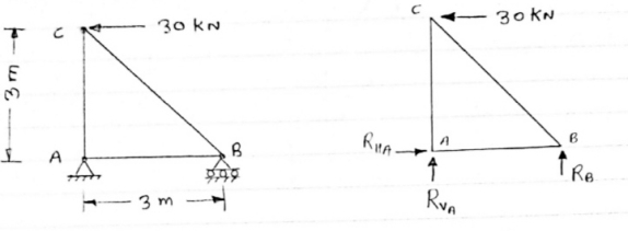
Answer 1) Consider FAB of Truss, Applying conditions of equilibrium,
 = 0
= 0
RHA + 30 Kn
 = 0
= 0
RvA + RB =0
Taking moment at point A, = 0
= 0
-(RB* 3) - (30*3) = 0
RB = -30 KN
RB =30 KN RVA = 30 KN
Consider Joint c, Assuming forces in member AC & BC to be
Tensile, Applying conditions of equilibrium, 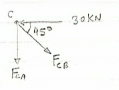
 = 0
= 0
-30 + FCB cos 45 =0
FCB =30/cos 45 = 42.42 KN (T)
-  = 0
= 0
- FcA – FCB sin 45=o
- F cA -42.42 sin 45 =0 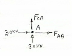
-FCA – 30= 0
-FCA = -30 KN
Consider Joint c, Assuming forces in member AC & BC to be
Tensile, Applying conditions of equilibrium,
 Fx = 0 30+FAB =0
FAB = -30KN
Question 2) Determine the forces in each member of the plane truss as shown in fig. In terms pf the external loading and state if the members are in tension or compression. Use 0+ 30 deg, L = 2 m and p =100N.
Diagram
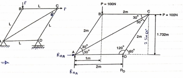
Answer 2) Consider FBD of Truss,
For equilibrium,  Fx =0
Fx =0
RHA+100 =0
RHA =-100 KN
 Fy =0 RVA = RD – 100 ….. 1
MA = 0 -------Taking moment @ A
- (Roxz) + (100*1) + (100*1.732) =0
- - 2 Rd + 100 + 1.7320 =0
- -2 Rd + 100 + 173.2 =0
- RD =136.66 N ()
From eqn (1)
RVA = 100 – 136.6
RVA= 36.6N
RVA = 36.6 N
Consider Joint D, for equilibrium,
Fx =0
-FAD + FCD cos 60 =0 – (11)
Fy = 0
136.6 +FCD sin 60 +0 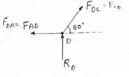
FCD = -157.73 N ©
From eqn (11), Fad =- 78. 87 N (c)
Consider point A, for the equilibrium of point A,
 Fx = 0
- 100 + FAD + FAc cos + 30 FAb cos60 = 0
-100 + (-78.87) +FAC cos 30 +FAb cos60 =0
FAc cos 30 + FAB cos60 + 178. 87 (3)
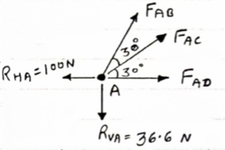
 fx =0
fx =0
-36.6 + FAC sin 30 + FAB sin 60 =0
FAC sin 30 + FAb sin 60 = 36.6
Solving eqn (3) and (4)
FAC = 273.21 N (T)
FAB = -115.47 N
FAB= 115.47 N ©
Consider point B, for the equilibrium of point,
 Fx =0
Fx =0
-FAB cos60 + FBC =0
-[9-115.47) cos60]+ FBC =0
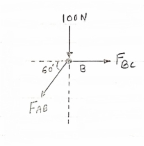
FBC = -57.73 N
FBC =57.73N
Member | AB | BC | CD | AD | AC |
Force | 115.47N | 57.73N | 157.73N | 78.87N | 273.21N |
Nature | c | c | c | c | T |
Question 3) Determine the axial forces in each member of the plane truss as shown in figure.
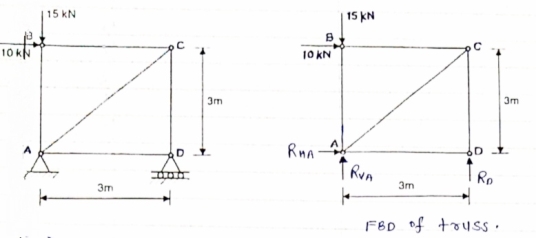
Answer 3) consider FBD of Truss,
For the equilibrium of Truss,  fx =0
fx =0
RHA + 10 =0
RHA = -10 KN
RHA =10KN (
Resolving forces vertically,
 fy =o
fy =o
RVA + RD -15 =0
RVA + RD = 15 …… (1)
Taking moment about point A,
 Fy =0
Fy =0
(10*3) – 3 Rd =0
30+ 3 Rd =0
RD= 10 KN 
RVA = 5KN ( )
)
Now Consider joint B, FBD of joint B is shown below.
Assumbing forces developed in all members to be Termile,
For the equilibrium of joint We have
 fx =0
fx =0
10+FBC =0 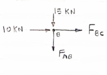
FBC = -10 KN
FBC = 10KN (c)
 fy =0
fy =0
FAB = -15 KN
FAB = 15 KN (c)
Now consider joint c,
For the equilibrium of joint,
 fx =0
fx =0
-FBC – FAC cos 45 =0
- (-10) – FAC cos 45=0
10= FAC cos 45
FAC = 10/cos 45 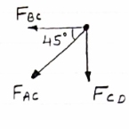
FAc = 14.14 KN (T)
 fy =0
fy =0
-Fac sin 45 – FCD=0
- 14.14 sin45 = FCD
FCD = -10 KN (c)
FCD= 10 KN (c)
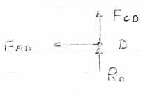
Consider joint D,
By observation,
FAD=0
Sr .No | Member | Force | Nature |
1 | AB | 15 KN | c |
2 | BC | 10KN | c |
3 | CD | 10KN | c |
4 | DA | 0 | - |
5 | AC | 14.14 | T |
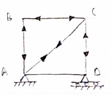
Question 4) Member AB & BC can support a maximum compressive force of 800 N & members AD, DC, BD can support a max. Tensile. Force of 2000N Determine the greatest land p that
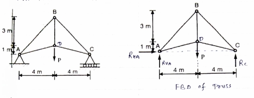
Answer 4) Consider following geometry of the figure.
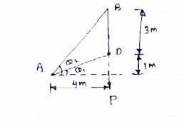
Tan 1 = ¼
1 = ¼
 14.04
14.04
 2 =
2 =  =45
=45
 Consider
 fx =0 RHA = 0
∈Fy =o RVA + Rc = p………(1)
∈ma =0
Hp- 8 Rc =0
Rc =P/2 N ( ) RvA = (P/2) N (
 )
)
Consider point A C assuming all forces as Tensile)
∈fx =0
FAD cos 14.04+FAB cos 45 =0… (2)
∈fy = 0 p/2= Fad sin 14.04 + FAB sin 45 =0….. (3)
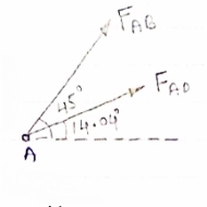
FAB = 2743.9 N > 800 N ( Not Allowed)
Let FAD = 2000 N (T) Then from eqn (2) & (3)
FAB =-274.9 N > 800 ( Not allowed)
Let FAB = .800 N ©, Then put this eqn (2) (3) we get
FAB = 583 N < 2000 N (Allowed) From Eqn (2) P= 848.9 N
Method of joint: This method involves isolating each joint of the truss and considering the equilibrium of the joint when determining the member axial force. Two equations used in determining the member axial forces are ∑ Fx = 0 and ∑ Fy = 0. Joints are isolated consecutively for analysis based on the principle that the number of the unknown member axial forces should never be more than two in the joint under consideration in a plane trust.
Analysis of Trusses by Method of Joint
This method is based on the principle that if a structural system constitutes a body in equilibrium, then any joint in that system is also in equilibrium and, thus, can be isolated from the entire system and analyzed using the conditions of equilibrium. The method of joint involves successively isolating each joint in a truss system and determining the axial forces in the members meeting at the joint by applying the equations of equilibrium. The detailed procedure for analysis by this method is stated below.
Procedure for Analysis
•Verify the stability and determinacy of the structure. If the truss is stable and determinate, then proceed to the next step.
•Determine the support reactions in the truss.
•Identify the zero-force members in the system. This will immeasurably reduce the computational efforts involved in the analysis.
•Select a joint to analyse. At no instance should there be more than two unknown member forces in the analysed joint.
•Draw the isolated free-body diagram of the selected joint, and indicate the axial forces in all members meeting at the joint as tensile (i.e. as pulling away from the joint). If this initial assumption is wrong, the determined member axial force will be negative in the analysis, meaning that the member is in compression and not in tension.
•Apply the two equations Σ Fx = 0 and Σ Fy = 0 to determine the member axial forces.
•Continue the analysis by proceeding to the next joint with two or fewer unknown member forces.

Method of section: This method entails passing an imaginary section through the truss to divide it into two sections. The member forces are determined by considering the equilibrium of the part of the truss on either side of the section. This method is advantageous when the axial forces in specific members are required in a truss with several members.

Analysis of Trusses by Method of Section
Sometimes, determining the axial force in specific members of a truss system by the method of joint can be very involving and cumbersome, especially when the system consists of several members. In such instances, using the method of section can be timesaving and, thus, preferable. This method involves passing an imaginary section through the truss so that it divides the system into two parts and cuts through members whose axial forces are desired. Member axial forces are then determined using the conditions of equilibrium. The detailed procedure for analysis by this method is presented below.
Procedure for Analysis of Trusses by Method of Section
•Check the stability and determinacy of the structure. If the truss is stable and determinate, then proceed to the next step.
•Determine the support reactions in the truss.
•Make an imaginary cut through the structure so that it includes the members whose axial forces are desired. The imaginary cut divides the truss into two parts.
•Apply forces to each part of the truss to keep it in equilibrium.
•Select either part of the truss for the determination of member forces.
•Apply the conditions of equilibrium to determine the member axial forces.