UNIT 1
D.C. Networks
The three essential elements in circuit analysis:
• Resistance R
• Capacitance C
• Inductance L
Their V and I relationships are summarized below
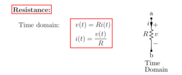
Resistance is a static element in the sense v(t) versus i(t) relationship is instantaneous. For example, v(t) at time t = 2 seconds simply depends only on i(t) at t = 2 seconds and nothing else. This implies that the resistance does not know what happened in the past, in other words it does not store any energy unlike other elements C and L.
Capacitance: Time domain:
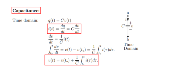
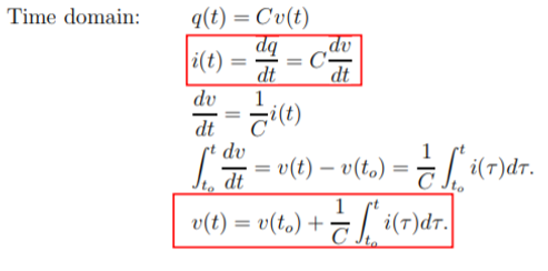
q(t) = Cv(t)
i(t) = dq /dt = C dv/ dt
Dv/dt = 1/C i(t)
 = v(t) – v(to) = 1/C
  d
d 
For a capacitance the v(t) versus i(t) relationship and vice versa at any time t depends on the past as they involve differentials and integrals. This implies that the capacitance is a dynamic element.
Inductance:

Time domain v(t) = L di/dt
Di/dt = 1/L v(t)
 = i(t) – i(to) = 1/L
  d τ
d τ
i(t) = i(to) + 1/L  dτ
dτ
The algebraic sum of currents meeting at a junction or node in an electric circuit is zero ② or the summation of all incoming current is always equal to summation of all outgoing current in an electrical network.
Explanation
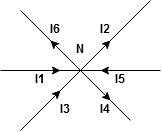
Assuming the incoming current to be positive and outgoing current negative we have


Ie incoming current = ∑ outgoing current thus, the above Law can also be stated as the sum of current flowing towards any junction in an electric circuit is equal to the sum of currents flowing away from that junction
Kirchhoff’s Voltage Law (KVL)
Statement: the algebraic summation of all Voltage in any closed circuit or mesh of loop zero.
Ie; ∑ Voltage in closed loop = 0 the summation of the Voltage rise (voltage sources) is equal to summation of the voltage drops around a closed loop in 0 circuit for explanation from here
Determination of sigh and direction of currents (Don’t write in exams just for understanding)

Current entering a resistor is +ve and leaving should be –ve
Now
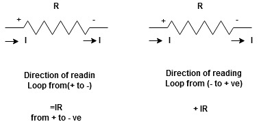


Potential Rise Potential Drop
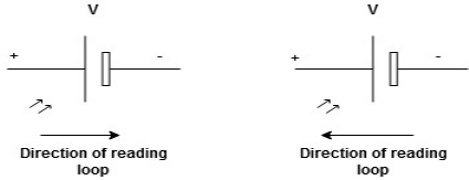
We are reading from +V to –V we are reading from –V to +V
 potential drops
  potential rise
 -V
-V  +V
+V
Given Circuit
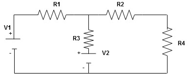
First identify no of loops and assign direction of current flowing in loop
Note: no of loops in circuit = No, of unknown currents = no, of equations in the circuit
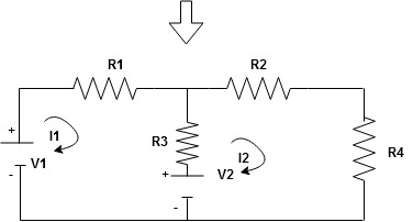
Note: keep loop direction and current direction same ie either clockwise or anticlockwise for all loops I1 I2
Now according to direction of direction assign signs (+ve to –ve) to the resistors
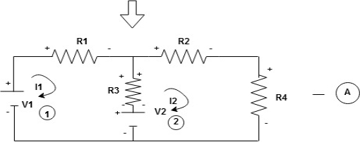
Note: voltage sources (V) polarities do not change is constant.
Note: for common resistor between 2 loops appearing in the circuit like R3 give signs according to separate loops as shown
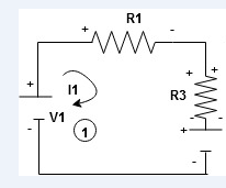
When considering only loop no 1 (+ R3 - )
- B
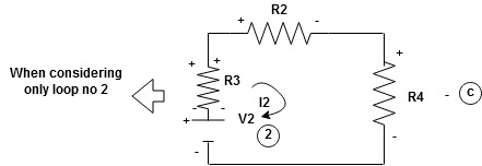
Now consider diagram A and write equations
Two loops  two unknown currents
  two equation
Apply KVL for loop ① [B. Diagram]
(+ To drop -) = - sign and (- to rise +) = + sign
 for drop = -sign
 for rise = + sign
-
-( ) R2 is considered because in R3,2 currents are flowing
  and
and  and we have taken (
 ) because we are considering loop no 1 and current flowing is
  in loop no 1
 )
)
Similarly for loop no. 2 currents flowing is  resistor R3 it should be
  )R3
)R3
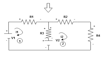
Consider loop no. 1 apply KVL
- …….①
…….①
-
Consider loop no. 2 apply KVL
- …….②
…….②
-
After solving equation ① and ② we will get branch current  and
and 
NODE ANALYSIS:
For these we assume every node as a voltage point and write the current equation for every element. For current source, current entering is negative.
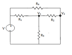
For node V1

For node V2

For V

Example: Using nodal analysis find voltage across 5resistor.
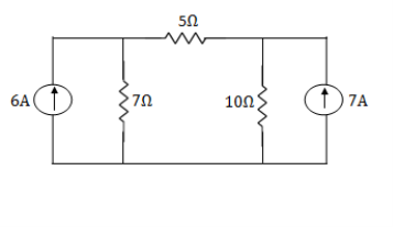
Solution:
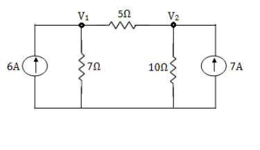
For V1


 1
1
For V2


 2
2
Solving 1 and 2:


For 5 voltage = 
= -50.9 + 57.27
= 6.37V
Mesh current:
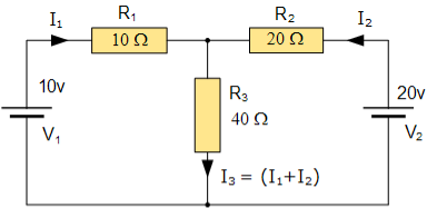
- Equation No 1 : 10 = 50I1 + 40I2
- Equation No 2 : 20 = 40I1 + 60I2
Mesh Current Analysis:
An easier method of solving the above circuit is by using Mesh Current Analysis or Loop Analysis which is also sometimes called Maxwell´s Circulating Currents method.
Instead of labelling the branch currents we need to label each “closed loop” with a circulating current.
Any required branch current may be found from the appropriate loop or mesh currents as before using Kirchhoff´s method.
For example: : i1 = I1 , i2 = -I2 and I3 = I1 – I2
Therefore,
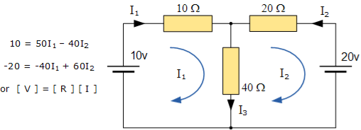
These equations can be solved quite quickly by using a single mesh impedance matrix Z. Each element ON the principal diagonal will be “positive” and is the total impedance of each mesh. Where as, each element OFF the principal diagonal will either be “zero” or “negative” and represents the circuit element connecting all the appropriate meshes.
[ V] = [I] x [R] or [R] x [I] = [V]

I = V/R = R-1 x V
Inverse of R = [ 60 40
40 50 ]
|R| = (60 x 50 ) – (40 x 40 ) = 1400
R – 1 = 1/1400 [ 60 40
40 50]
Having found the inverse of R, as V/R is the same as V x R-1, we can now use it to find the two circulating currents.
[I] = [ R -1] x [V]
[ I1]= 1/1400 [ 60 40 [10]
[I2 ] = 40 50 ] x [ -20]
I1 = (60 x 10 ) + (40 x -20 ) /1400 = -200/1400 = -0.143 A
I2 = (40 x 10 ) + (50 x -20) /1400 = -600/1400 = -0.429A
Where:
- [ V ] gives the total battery voltage for loop 1 and then loop 2
- [ I ] states the names of the loop currents which we are trying to find
- [ R ] is the resistance matrix
- [ R-1 ] is the inverse of the [ R ] matrix
And this gives I1 as -0.143 Amps and I2 as -0.429 Amps
As : I3 = I1 – I2
The combined current of I3 is therefore given as : -0.143 – (-0.429) = 0.286 Amps
Statement:
The response in any element of the linear bilateral network containing more than one source is the sum of the responses produced by the individual source acting alone. The responses mean the voltage across the element or the current in the element the voltage sources should be replaced by a short circuit and the current source must be replaced by an open circuit.Steps to apply superposition theorem :
1.
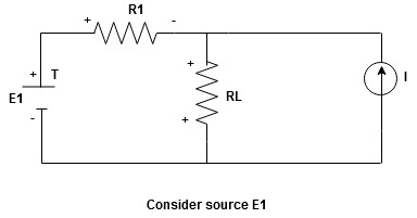
Current sources should be open
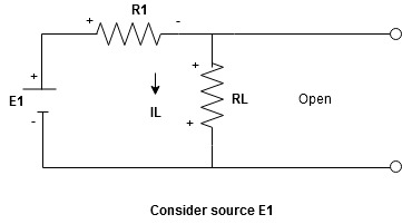
Find the current (IL1)(+) through or the voltage across the required element due to the source under consideration using a suitable n/w technique.
- Consider the current source (I) Voltage source should be a short circuit
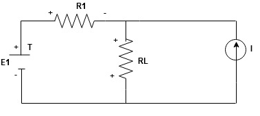
Find the current (ILII)(+) by a suitable network simplification technique
2. Add the individual current IL and ILII by the individual sources acting alone to find the total current flowing in load resistance (RL)
Ie L =
L = L
L +
+  L
L 
- Magnetic motive force MMF: It is the force that is required for production of flux
MMF = No. Of turns x current
= N x I
= Ampere Turns
=AT
2. Magnetic field strength / intensity / magnetising force:
It is the force experienced by a unit north poles placed at that point in the magnetic field Denoted by H
Measured in Newtown / wb or AT/n
H = N/wb
N/wb
H = 
3. Reluctance:
It is defined as the opposition to the flow of flux in a material
Reluctance is denoted by S and measured in AT/wb or Siemens
S = ɺ/ μ₀μᵣₐ - AT/wb
It can also be defined as the ratio of (MMF) to the magnetic flux (Ø)
S =  - AT/wb
4. Leakage coefficient:
The leakage coefficient or leakage factor indicates the percentage or part of total flux lost due to leakage. It is defined as the ratio of total flux (Ø7) to useful / air gap flux Øu
Leakage factor (h) = 
It is also called as Hopkinson’s coefficient value is from 1.1 to 1.25
5. Magnetic fringing :
The tendency of the magnetic flux to spread out at the edges of the air gap is called magnetic fringing
6. Effect of fringing:
- Increases cross sectional area of airgap
 the flux density (B) is reduce
Core loss is broadly classified into:
Hysteresis loss
Eddy current loss
Hysteresis Loss:
The loss occurs due to reversal of armature core is said to be hysteresis loss. Each part of the rotor core passes under the North Pole N and South Pole S alternately and attains S and N polarity, respectively. When the core passes under one pair of poles, the core is said to complete one cycle of frequency reversal. Hysteresis loss ∝ B maxn f.
Eddy current Loss:
The armature core cuts the magnetic flux during its rotation and emf is induced in the surface of the core, according to the laws of electromagnetic induction. This emf is very small, but it sets up a large current in the surface of the core. This lager current is called the eddy current and the loss is known as the eddy current loss. Eddy current loss ∝ Bmax2 f2.
Core losses are constant for shunt and compound generators, as their field currents are approximately constant. Core loss is about 20 % to 30 % of full-load losses.
Electric magnetic
- Current is actual flow of electrons 1. Flux does not flow in the mag circuit
- Energy is required to produce the 2. Energy is required to produce
Current and maintain it flux but not for its maintenance
3. Current does not pass through air 3. Flux can pass through air
4. Resistance is independent of the 4. Reluctance of current changes with of the current flux
5.  5.
5. 
6. Current is reduced to zero after 6. Residual flux persists after removal of removal of emf mmf
7.  7.
7. 
Current density Flux density
8.  8.
8. 
9. Conductance =  9. Permeance =
10. Electric field Intensity  10. Magnetic filed Intensity
11. emf drop = I x R 11. Mmf drop = Ø x S
Eg .No.1
A magnetic circuit with a single air gap is shown in below figure. The core dimensions are:
Cross-sectional area Ac = 1.8 × 10⁻³ m2
Mean core length lc = 0.6 m
Gap length g = 2.3 x 10⁻³ m
N = 83 turns
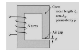
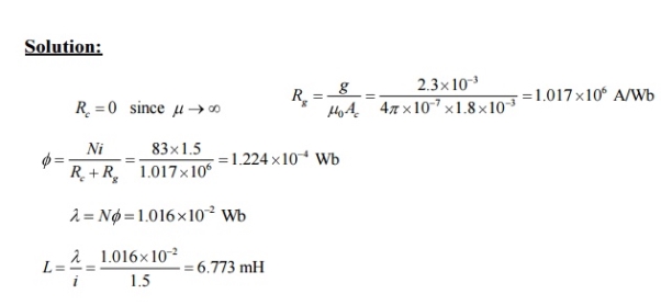
Assume that the core is of infinite permeability ( m -> ¥) and neglect the effects of fringing fields at the air gap and leakage flux. (a) Calculate the reluctance of the core
Re and that of the gap Rg. For a current of i = 1.5 A, calculate (b) the total flux ϕ, (c) the flux linkages λ of the coil, and (d) the coil inductance L.
Eg .No.2
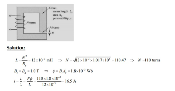
Consider the magnetic circuit of with the dimensions of Problem 1.1. Assuming density of 1.0 T.infinite core permeability, calculate (a) the number of turns required to achieve an inductance of 12 mH and (b) the inductor current which will result in a core flux
