Unit 3
Wave Optics
Contents:
The principle of superposition may be applied to waves whenever two (or more) waves travelling through the same medium at the same time. The waves pass through each other without being disturbed. The net displacement of the medium at any point in space or time, is simply the sum of the individual wave displacements. This is true of waves which are finite in length (wave pulses) or which are continuous sine waves
When two coherent light waves are superimposed, in the region of superposition the intensity of light gets modified. This modification in the distribution of intensity in the region of superposition is called interference. At some points the intensity is maximum (points of constructive interference) and at some points it is minimum or almost zero (points of destructive interference).
Condition for Interference
To obtain the stable interference pattern the following conditions are required
Condition for Sustained Interference Pattern
a. The two interfering waves should be coherent i.e., both light waves are in same phase or maintain constant phase difference between them.
b. The source must be monochromatic
c. Both the wave must be in same set of polarization.
Condition for observation of fringes
a. The distance between the coherent sources be small
b. The distance between the source and screen must be large
Condition for Good Contrast
a. The amplitude of the both interfering waves be the same or very nearly same.
b. The sources must be narrow
c. The interfering angle should be very small or both travel in the same direction.
To produce interference, coherent sources are required. If two or more waves have the same wave length (or frequency) and they are in phase or maintain constant phase relationship then they are said to be coherent. Coherent sources cannot be obtained from separate light sources but they are obtained from a single light source.
The coherence is of two types, namely (i) Temporal coherence and (ii) Spatial coherence.
(i) Temporal coherence: If the phase of an electromagnetic field at a point does not change at a given time then the field is said to be temporally coherent during that time. Suppose E(x, y,z, t1) is the field at time ‘t1’ and E(x, y, z, t2) is the field at a later time ‘t2’. During this period if the phase is not changed at that point then the field is said to be temporally coherent. Suppose the phase changes many times during this period then it is said to be non-coherent.
(ii) Spatial coherence: Waves are said to be spatially coherent, if they maintain a constant phase difference at different points over any time ‘t’.
Division of Wavefront
In this method the incident wavefront is divided into two separate wavefront which when further moves are superimposed and produce an interference pattern.
For example: Young’s experiment, Fresnel’s biprism, etc.
Division of Amplitude
In this method the intensity (amplitude) of the wave is divided by the phenomenon of partial reflection and partial refraction.
For example: Interference in thin film, Newton’s Ring Experiment, etc
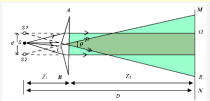
A Fresnel Biprism is a thin double prism placed base to base and have very small refracting angle (0.5 degree). This is equivalent to a single prism with one of its angles nearly 179° and other two of 0.5degree each.
The interference is observed by the division of wave front. Monochromatic light through a narrow-slit S falls on biprism, which divides it into two components. One of these components is refracted from upper portion of biprism and appears to come from S1 where the other one refracted through lower portion and appears to come from S2. Thus, S1 and S2 act as two virtual coherent sources formed from the original source. Light waves arising from S1and S2 interfere in the shaded region and interference fringes are formed which can be observed on the screen.
Applications of Fresnel's Biprism
Fresnel biprism can be used to determine the wavelength of a light source (monochromatic), thickness of a thin transparent sheet/ thin film, refractive index of medium etc.
A. Determination of wave length of light
As expression for fringe width is 
Biprism can be used to determine the wavelength of given monochromatic light using the expression.

Experimental Arrangement.
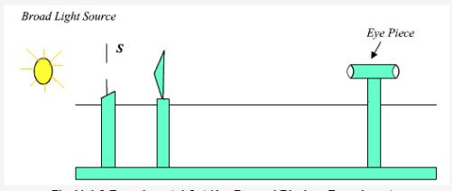
Light from monochromatic source is made to fall on a thin slit mounted vertically on a rigid optical bench fitted with a scale. The biprism and the screen (in this case an eye piece) are also mounted vertically. The eye piece can be moved in the plane perpendicular to the axis of bench using a micrometer based translation stage.
(i)Measurement of fringe width:
To get β, fringes are first observed in the field of view of the microscope. The vertical wire of the eyepiece is made to coincide with one of the fringes and screw of micrometer is moved sideways and number of fringes is counted.
β =Distance moved / number of fringes passed
(ii) Measurement of D:
This distance between source and eyepiece is directly measured on the optical bench scale.
(iii) Determination of d:
To determine the separation between the two virtual sources (d), a convex lens of short focal length is introduced between the biprism and the eye piece, keeping the distance between the slit and eyepiece to be more than four times the focal length of lens. The lens is moved along the length of bench to a position where two images of slits are seen in the plane of cross wires of eye piece. The distance between these two images of slit is measured by setting the vertical cross wire successively on each of images and recording the two positions of cross wire using micrometer. Let this separation be d1. Now the lens is moved such that for another position of lens, again two images of slit are seen on eye piece. Let d2 be the separation between these two images.
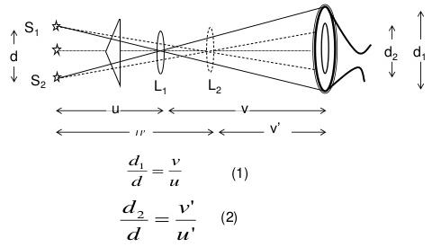
Since these two positions of lens are conjugate, the separation between the virtual source ‘d ' is given by using 1 and 2 as

The separation between the virtual source ‘d ' is given as

Where d1 and d2 are the distance between S1 and S2 for two position of lens.
To determine the thickness of transparent thin sheet (mica), the monochromatic source is replaced by white light source. In this case the fringe pattern consists of several fringe patterns corresponding to all wavelength and the resultant of this is a central white fringe surrounded by dark region.
The position of this central white fringe is recorded by focusing the cross wire of eye piece on it and taking this reading of micrometer scale. Now mica sheet is introduced in the path of one wave. (such that it blocks the one half of biprism). By doing it the one wave traverse an extra optical path and the path difference between the two waves is not same and entire fringe pattern shifts. The central white fringe is now shifted to another position of cross wire. If ‘S' is the shift in position of white fringe and  be the refractive index of mica sheet, thickness ‘t' of mica sheet is given by
 cm
cm
Interference in Wedge Shaped Film (Reflected Rays)
The wedge-shaped film has a thin film of varying thickness, having thickness zero at one end and increases at the other. The angle of wedge is  .
.
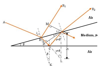
The optical path difference between the two reflected rays R1 and R2 will be

From the geometry

As in ΔBMD;

And in ΔBND

According Snell’s Law,

Or 
Thus 


As in ΔNDL

Correction on account of phase change at reflection: when a beam is reflected from a denser medium (ray R1 at B), a path change of  /2 occur for the ray.
There-fore the true path difference is

Condition of Maxima (Bright Fringe)
Maxima occur when path difference,


Condition for Minima (Dark Fringe)
Minima occur when path difference


Newton's rings are the circular interference pattern first discovered by Newton.
Formation of fringes
When a plano-convex lens with large radius of curvature is placed on a plane glass plate such that its curved surface faces the glass plate, a wedge air film (of gradually increasing thickness) is formed between the lens and the glass plate. The thickness of the air film is zero at the point of contact and gradually increases away from the point of contact.
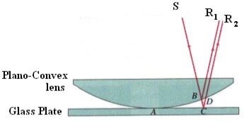
If monochromatic light is allowed to fall normally on the lens from a source 'S', then two reflected rays R1 (reflected from upper surface of the film) and R2 (reflected from lower surface of the air film) interfere to produce circular interference pattern. This interference pattern has concentric alternate bright and dark rings around the point of contact.
Theory of Fringes:
The effective path difference between the two reflected rays R1 and R2 for a wedge-shaped film

If the light is incident normally on the lens, r = 0 and near to point of contact  is small; there-fore near point of contact,
Therefore 
At point of contact t = 0 therefore the effective path difference ∆ = λ/2 which is odd multiple of λ/2 There-fore the Central fringe is dark.
Condition of Maxima (Bright Fringe): The effective path difference  ; substituting this


Condition for Minima (Dark Fringe): The effective path difference ; substituting this in equation

 …
…
From above it is clear that for particular dark or bright fringe t should be constant.
Every fringe is the locus of points having equal thickness. Hence the fringes are circular in shape.
Diameter of Newton’s Rings:
To calculate the diameter of fringes, assume a plano-convex lens is placed on a plane glass plate as shown in figure say R be the radius of curvature of lens. In ΔO’ML
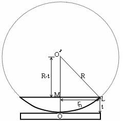


As t << R; neglecting t2 (small value)


Diameter of Dark Rings
Substitute this


As Dn = 2rn


The medium enclosed between the lens and glass plate is if air therefore,  = 1. The diameter of nth order dark fringe will be
 ….
….
 ; n = 0, 1, 2, 3, 4….
The diameter of dark ring is proportional to square root of natural numbers
Diameter of Bright Rings
Substitute t above:


As Dn = 2rn


The medium enclosed between the lens and glass plate is if air therefore, = 1. The diameter of nth order bright fringe will be
 …..
…..
 ; n = 0, 1, 2, 3, 4….
The diameter of bright ring is proportional to square root of odd natural numbers
Spacing between Fringes
The Newton’s rings are not equally spaced because the diameter of ring does not increase in the same proportion as the order of ring and rings get closer and closer as ‘n’ increases.
For example, the diameter of dark ring is given by
Where n = 0, 1, 2, 3, 4….


From above, we conclude that the fringe width reduces with increase in ‘n’.
Newton’s Ring with White Light
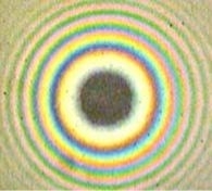
If the monochromatic source is replaced by the white light few coloured rings are seen around dark centre later illumination is seen in the field of view.
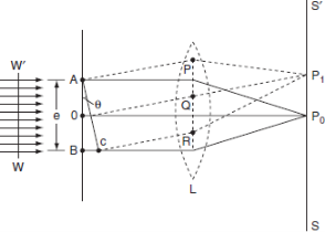
The adjacent figure represents a narrow-slit AB of width ‘e’. Let a plane wavefront of monochromatic light of wavelength ' ' is incident on the slit. Let the diffracted light be focused by means of a convex lens on a screen. According to Huygens Fresnel, every point of the wavefront in the plane of the slit is a source of secondary wavelets. The secondary wavelets traveling normally to the slit i.e., along OP are brought to focus at Po by the lens. Thus, Po is a bright central image. The secondary wavelets travelling at an angle '
 ' are focused at a point P1 on the screen.
The intensity at the point P1 is either minimum or maximum and depends upon the path difference between the secondary waves originating from the corresponding points of the wavefront.
Theory:
In order to find out the intensity at P1, draw a perpendicular AC on BR.
The path difference between secondary wavelets from A and B in direction q is BC i.e.,

So, the phase difference,


Let us consider that the width of the slit is divided into ‘n’ equal parts and the amplitude of the wave from each part is ‘a’.
So, the phase difference between two consecutive points

Then the resultant amplitude R is calculated by using the method of vector addition of amplitudes
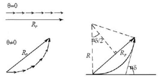
The resultant amplitude of n number of waves having same amplitude 'a' and having common phase difference of ' ' is
' is

Substituting the value of  in equation
Substituting  in equation

As  is small value;
 and na = A
Therefore
 .
.
Therefore, the Intensity is given by

Case (i): Principal Maximum:
Take maximum value for
 = 0
= 0

 or
or 
The condition  means that this maximum is formed by the secondary wavelets which travel normally to the slit along OPo and focus at Po. This maximum is known as “Principal maximum”.
Intensity of Principal maxima


Therefore

Case (ii): Minimum Intensity positions:
Take minimum values for sin = 0. The values of '
 ' which satisfy
  are
are


 where
where 
In the above eqn n = 0 is not applicable because corresponds to principal maximum. Therefore, the positions according to eqn are on either side of the principal maximum.
Case (iii): Secondary maximum:
In addition to principal maximum at  = 0, there are weak secondary maxima between minima positions. The positions of these weak secondary maxima can be obtained with the rule of finding maxima and minima of a given function in calculus. So, differentiating eqn and equating to zero, we have

Because  correspond to minima positions

 .
.
The values of ' ' satisfying the eqn are obtained graphically by plotting the curves
  and
and 
On the same graph. The points of intersection of the two curves gives the values of ' ' which satisfy eqn.
The points of intersections are

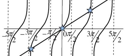
But  , gives principal maximum, substituting the values of '
 ' in eqnwe get


And so on.
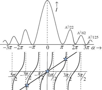
From the above expressions, Imax, I1, I2,I3… it is evident that most of the incident light is concentrated at the principal maximum.
Intensity distribution graph:
A graph showing the variation of intensity with ' ' is as shown in the adjacent figure
Rayleigh Criterion of Resolution
Statement:
Two sources are resolvable by an optical instrument when the central maximum of one diffraction pattern falls over the first minimum of the other diffraction pattern and vice versa.
For example:
Let us consider the resolution of two wavelengths and by a grating. When the difference in wavelengths is smaller and such that the central maximum of the wavelength coincides with the first minimum of the other as shown in figure, then the resultant intensity curve is as shown by the thick curve. The curve shows a distinct dip in the middle of two central maxima. Thus, the two wavelengths can be distinguished from one another and according to Rayleigh they are said to be “Just Resolved”.
If the difference in wavelengths is such that their principal maxima are separately visible, then there is a distinct point of zero intensity in between the two wavelengths. Hence according to Rayleigh, they are said to be “Resolved”.
When the difference in wavelengths is so small that the central maxima corresponding to two wavelengths come still closer as shown in figure, then the resultant intensity curve is quite smooth without any dip. This curve is as if there is only one wavelength somewhat bigger and stronger.
Hence according to Rayleigh, the two wavelengths are “Not Resolved”.
Thus, the two spectral lines can be resolved only up to a certain limit expressed by Rayleigh Criterion.

Application to vision
If all parts of an imaging system are considered to be perfect, then the resolution of any imaging process will be limited by diffraction. Considering the single slit expression above, then when the wavelength is equal to the slit width, the angle for the first diffraction minimum is 90°. This means that the wave is spread all the way to the plane of the slit and will not contain resolvable information about the source of the wave. This leads to the simplified statement that the limit of resolution of any imaging process is going to be on the order of the wavelength of the wave used to image it.
Resolving Power of Grating
It is defined as the capacity of a grating to form separate diffraction maxima of two wavelengths which are very close to each other
It is measured by  where
where  is the smallest difference in two wavelengths which are just resolvable by grating and
 is the wavelength of either of them or mean wavelength.
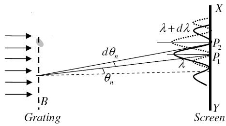
Let AB represent the surface of a plane transmission grating having grating element (e+d) and N total number of slits. Let a beam of light having two wavelengths  and
and  is normally incident on the grating. Let P1 is nth primary maximum of a spectral line of wavelength
  at an angle of diffraction
  and P2 is the nth primary maximum of wavelength
  at diffracting angle
According to Rayleigh criterion, the two wavelengths will be resolved if the principal maximum  of nth order in a direction
  falls over the first minimum of nth order in the same direction
  . Let us consider the first minimum of l of nth order in the direction
  as below.
The principal maximum of  in the
  direction is given by
 ...
...
The equation of minima is  where m takes all integers except 0, N, 2N, …, nN, because for these values of m, the condition for maxima is satisfied. Thus, first minimum adjacent to nth principal maximum in the direction
 can be obtained by substituting the value of ‘m’ as (nN+1). Therefore, the first minimum in the direction of
  is given by

 ..
..
The principal maximum of  in direction
  is given by
 ..
..
Dividing eqns, we get


 .
.
Thus, the resolving power is directly proportional to
(i) The order of the spectrum ‘n’
(ii) The total number of lines on the grating ‘N’