Unit 6
Faraday’s law and Electromagnetic waves
Contents:
Faraday’s law of electromagnetic induction, also known as Faraday’s law is the basic law of electromagnetism which helps us to predict how a magnetic field would interact with an electric circuit to produce an electromotive force (EMF). This phenomenon is known as electromagnetic induction.
Faraday’s Laws of Electromagnetic Induction
Faraday’s Laws of Electromagnetic Induction consists of two laws. The first law describes the induction of emf in a conductor and the second law quantifies the emf produced in the conductor. In the next few sections, let us learn these laws in detail.
Faraday’s First Law of Electromagnetic Induction
The discovery and understanding of electromagnetic induction are based on a long series of experiments carried out by Faraday and Henry. From the experimental observations, Faraday arrived at a conclusion that an emf is induced in the coil when the magnetic flux across the coil changes with time. With this in mind, Faraday formulated his first law of electromagnetic induction as,
Whenever a conductor is placed in a varying magnetic field, an electromotive force is induced. If the conductor circuit is closed, a current is induced which is called induced current.

Mentioned here are a few ways to change the magnetic field intensity in a closed loop:
- By rotating the coil relative to the magnet.
- By moving the coil into or out of the magnetic field.
- By changing the area of a coil placed in the magnetic field.
- By moving a magnet towards or away from the coil.
Faraday’s Second Law of Electromagnetic Induction
Faraday’s second law of electromagnetic induction states that the induced emf in a coil is equal to the rate of change of flux linkage.
The flux is the product of the number of turns in the coil and the flux associated with the coil. The formula of Faraday’s law is given below:

Where,
- ε is the electromotive force
- Φ is the magnetic flux
- N is the number of turns
The negative sign indicates that the direction of the induced emf and change in the direction of magnetic fields have opposite signs.
Additionally, there is another key law known as Lenz’s law that describes electromagnetic induction as well.
Faraday’s Law Formula
Consider a magnet approaching towards a coil. Consider two-time instances T1 and T2.
Flux linkage with the coil at the time T1 is given by
T1 = NΦ1
Flux linkage with the coil at the time T2 is given by
T1 = NΦ2
Change in the flux linkage is given by
N(Φ2 – Φ1)
Let us consider this change in flux linkage as
Φ = Φ2 – Φ1
Hence, the change in flux linkage is given by
NΦ
The rate of change of flux linkage is given by
NΦ/t
Taking the derivative of the above equation, we get
N dΦ/dt
According to Faraday’s second law of electromagnetic induction, we know that the induced emf in a coil is equal to the rate of change of flux linkage. Therefore,
E=Ndϕ/dt
Considering Lenz’s law,
E=−Ndϕ/dt
From the above equation, we can conclude the following
- Increase in the number of turns in the coil increases the induced emf.
- Increasing the magnetic field strength increases the induced emf.
- Increasing the speed of the relative motion between the coil and the magnet, results in the increased emf.
|
The Continuity Equation
If we do some simple mathematical tricks to Maxwell's Equations, we can derive some new equations. On this page, we'll look at the continuity equation, which can be derived from Gauss' Law and Ampere's Law.
To start, I'll write out a vector identity that is always true, which states that the divergence of the curl of any vector field is always zero:
|  |
|
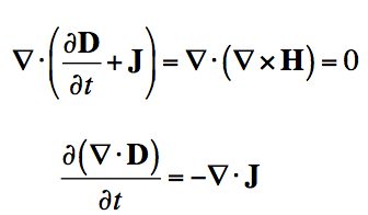
If we apply the divergence to both sides of Ampere's Law, then we obtain:
|  |
|
If we apply Gauss' Law to rewrite the divergence of the Electric Flux Density (D), we have derived the continuity equation:
|  |
|
But what does it mean? The left side of the equation is the divergence of the Electric Current Density (J). This is a measure of whether current is flowing into a volume (i.e. the divergence of J is positive if more current leaves the volume than enters).
Recall that current is the flow of electric charge. So, if the divergence of J is positive, then more charge is exiting than entering the specified volume. If charge is exiting, then the amount of charge within the volume must be decreasing. This is exactly what the right side is a measure of - how much electric charge is accumulating or leaving in a volume. Hence, the continuity equation is about continuity - if there is a net electric current is flowing out of a region, then the charge in that region must be decreasing. If there is more electric current flowing into a given volume than exiting, than the amount of electric charge must be increasing.
Apart from conduction current, there is another type of current called displacement current. It does not appear from the real movement of electric charge as is the case for conduction current.
Displacement current is a quantity appearing in Maxwell’s equations. Displacement current definition is defined in terms of the rate of change of the electric displacement field (D).
It can be explained by the phenomenon observed in a capacitor.
Current in a capacitor:
When a capacitor starts charging there is no conduction of charge between the plates. However, because of change in charge accumulation with time above the plates, the electric field changes causing the displacement current as below-
ID=JDS=S *∂D/∂t
Where,
- S is the area of the capacitor plate.
- ID is the displacement current.
- JD is the displacement current density.
- D is related to electric field E as D=εE
- ε is the permittivity of the medium in between the plates.
Displacement Current Equation
Displacement current has the same unit and effect on the magnetic field as is for conduction current depicted by Maxwell’s equation-
▽×H=J+JD
Where,
- H is related to magnetic field B as B=μH
- μ is the permeability of the medium in between the plates.
- J is the conducting current density.
- JD is the displacement current density.
We know that
(×H)=0 and ▽.J=−∂ρ/∂t=−▽.∂D/∂t
Using Gauss’s law that is ▽.D=ρ
Here, ρ is the electric charge density.
Thus, JD=∂D/∂t displacement current density is necessary to balance RHS with LHS of the equation.
Now we understand that there are two sources of a magnetic field:
- Conduction electric current due to the flow of charges
- Displacement current due to the rate of change of the electric field
Hence, the total current (i) is calculated as follows: (where ic – conduction current and id – displacement current)
i = ic + id
= ic + ε0(dQ/dt)
This means that –
- Outside the capacitor plates: ic=i and id=0
Inside the capacitor plates: ic=0 and id=i
Magnetic field arising from time dependent electric field
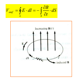
This emf induced by the time-varying current (producing the time-varying B field) in a stationary loop is often referred to as transformer emf in power analysis since it is due to transformer action. By applying Stokes's theorem to the middle term in eq. (1.4), we obtain

For the two integrals to be equal, their integrands must be equal; that is,

This is one of the Maxwell's equations for time-varying fields. It shows that the time varying E field is not conservative ( x E 0). This does not imply that the principles of energy conservation are violated. The work done in taking a charge about a closed path in a time-varying electric field, for example, is due to the energy from the time-varying magnetic field.
Maxwell's equations represent one of the most elegant and concise ways to state the fundamentals of electricity and magnetism. From them one can develop most of the working relationships in the field. Because of their concise statement, they embody a high level of mathematical sophistication and are therefore not generally introduced in an introductory treatment of the subject, except perhaps as summary relationships.
These basic equations of electricity and magnetism can be used as a starting point for advanced courses, but are usually first encountered as unifying equations after the study of electrical and magnetic phenomena.
Integral form in the absence of magnetic or polarizable media:
I. Gauss' law for electricity |  |
II. Gauss' law for magnetism |  |
III. Faraday's law of induction |  |
IV. Ampere's law |  |
5. Energy in an electromagnetic field
Electromagnetic waves can bring energy into a system by virtue of their electricand magnetic fields. These fields can exert forces and move charges in the system and, thus, do work on them. If the frequency of the electromagnetic wave is the same as the natural frequencies of the system (such as microwaves at the resonant frequency of water molecules), the transfer of energy is much more efficient.
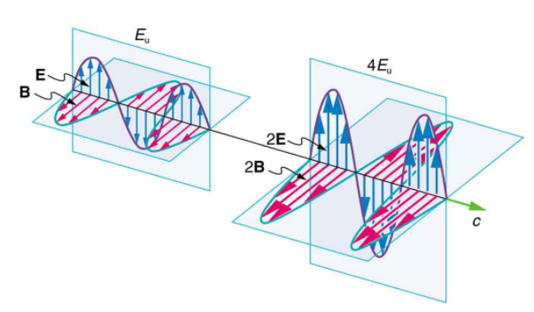
But there is energy in an electromagnetic wave, whether it is absorbed or not.
Once created, the fields carry energy away from a source. If absorbed, the field strengths are diminished and anything left travels on. Clearly, the larger the strength of the electric and magnetic fields, the more work they can do and the greater the energy the electromagnetic wave carries.
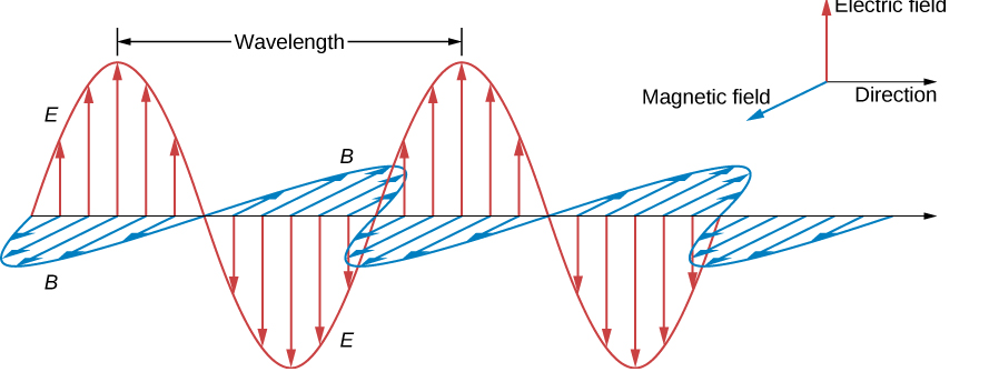
A wave’s energy is proportional to its amplitude squared (E2 or B2). This is true for waves on guitar strings, for water waves, and for sound waves, where amplitude is proportional to pressure. In electromagnetic waves, the amplitude is the maximum field strength of the electric and magnetic fields. (See Figure 1.)
Thus, the energy carried and the intensity I of an electromagnetic wave is proportional to E2 and B2. In fact, for a continuous sinusoidal electromagnetic wave, the average intensity Iave is given by

Where c is the speed of light, ε0 is the permittivity of free space, and E0 is the maximum electric field strength; intensity, as always, is power per unit area (here in W/m2).
The average intensity of an electromagnetic wave Iave can also be expressed in terms of the magnetic field strength by using the relationship B=E/c, and the fact that ϵ0=1μ0/c2 where μ0 is the permeability of free space. Algebraic manipulation produces the relationship

Where B0 is the maximum magnetic field strength.
One more expression for Iave in terms of both electric and magnetic field strengths is useful. Substituting the fact that c ⋅ B0 = E0, the previous expression becomes

Whichever of the three preceding equations is most convenient can be used, since they are really just different versions of the same principle: Energy in a wave is related to amplitude squared. Furthermore, since these equations are based on the assumption that the electromagnetic waves are sinusoidal, peak intensity is twice the average; that is,
I0 = 2Iave.
Electromagnetic waves bring energy into a system by virtue of their electric and magnetic fields. These fields can exert forces and move charges in the system and, thus, do work on them. However, there is energy in an electromagnetic wave itself, whether it is absorbed or not. Once created, the fields carry energy away from a source. If some energy is later absorbed, the field strengths are diminished and anything left travels on.
Clearly, the larger the strength of the electric and magnetic fields, the more work they can do and the greater the energy the electromagnetic wave carries. In electromagnetic waves, the amplitude is the maximum field strength of the electric and magnetic field. The wave energy is determined by the wave amplitude.
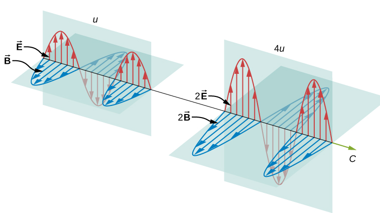
For a plane wave travelling in the direction of the positive x-axis with the phase of the wave chosen so that the wave maximum is at the origin at t=0t=0, the electric and magnetic fields obey the equations.

The energy in any part of the electromagnetic wave is the sum of the energies of the electric and magnetic fields. This energy per unit volume, or energy density u, is the sum of the energy density from the electric field and the energy density from the magnetic field. Expressions for both field energy densities were discussed earlier (uE in Capacitance and uB in Inductance). Combining these contributions, we obtain


Then shows that the magnetic energy density uB and electric energy density uE are equal, despite the fact that changing electric fields generally produce only small magnetic fields. The equality of the electric and magnetic energy densities leads to

The energy density moves with the electric and magnetic fields in a similar manner. The energy per unit area per unit time passing through a plane perpendicular to the wave, called the energy flux and denoted by S, can be calculated by dividing the energy by the area A and the time interval Δt.

More generally, the flux of energy through any surface also depends on the orientation of the surface. To take the direction into account, we introduce a vector S→, called the Poynting vector, with the following definition:

An electromagnetic wave consists of an electric field, defined as usual in terms of the force per charge on a stationary charge, and a magnetic field, defined in terms of the force per charge on a moving charge. The electromagnetic field is assumed to be a function of only the x-coordinate and time. The y-component of the electric field is then written as Ey (x, t), the z-component of the magnetic field as Bz (x, t), etc. Because we are assuming free space, there are no free charges or currents, so we can set Qin=0 and I=0 in Maxwell’s equations.
I. Gauss' law for electricity |  |
II. Gauss' law for magnetism |  |
III. Faraday's law of induction |  |
IV. Ampere's law |  |
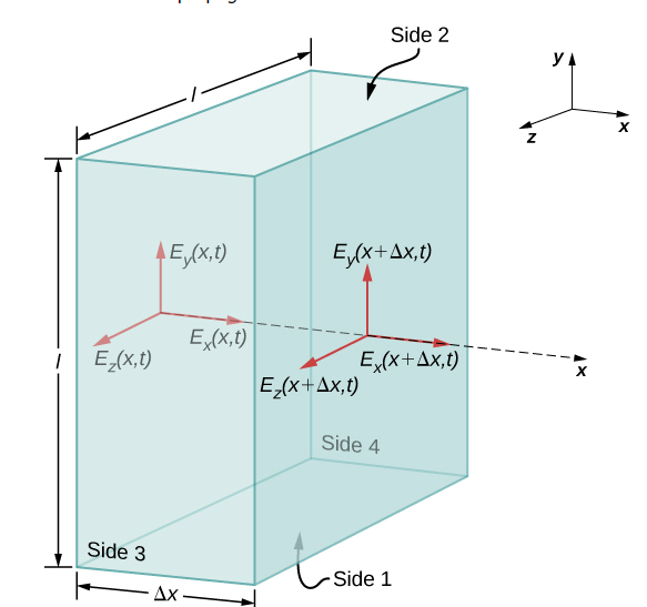
We examine first what Gauss’s law for electric fields implies about the relative directions of the electric field and the propagation direction in an electromagnetic wave. Assume the Gaussian surface to be the surface of a rectangular box whose cross-section is a square of side l and whose third side has length Δx. Because the electric field is a function only of x and t, the y-component of the electric field is the same on both the top and bottom of the box, so that these two contributions to the flux cancel. The corresponding argument also holds for the net flux from the z-component of the electric field through Sides 3 and 4. Any net flux through the surface therefore comes entirely from the x-component of the electric field. Because the electric field has no y- or z-dependence, Ex(x,t) is constant over the face of the box with area A and has a possibly different value Ex(x+Δx,t) that is constant over the opposite face of the box.
Applying Gauss’s law gives

Where A=l×l is the area of the front and back faces of the rectangular surface. But the charge enclosed is Qin=0, so this component’s net flux is also zero, and implies Ex(x,t)=Ex(x+Δx,t) for any Δx. Therefore, if there is an x-component of the electric field, it cannot vary with x. A uniform field of that kind would merely be superposed artificially on the travelling wave, for example, by having a pair of parallel-charged plates. Such a component Ex(x, t) would not be part of an electromagnetic wave propagating along the x-axis; so, Ex(x,t)=0 for this wave. Therefore, the only non zero components of the electric field are Ey(x,t) and Ez(x, t) perpendicular to the direction of propagation of the wave.
Polarisation:
The polarization of electromagnetic wave (EMW) is the basic property of the EMW, which is widely used and controlled in Laser, interferometer and photography
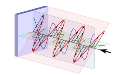
Linear Polarization
Assume Ey in the mathematical expression for the electric field equals to zero, which gives the definition of electric field as:
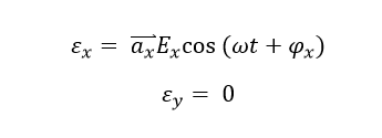
The electric field on certain propagation position will oscillate only on the x-axis with the angular frequency of omega, which is shown as below:
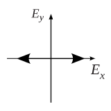
Thus, the similar polarization of electric field on only a specific straight direction is defined as linear polarization. On the other hand, Assume Ey equals to zero, which gives the electric field as:
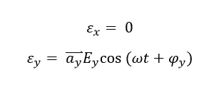
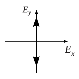
The electric field only oscillate on the y-axis with the angular frequency of omega, which is shown
Circular Polarization
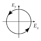
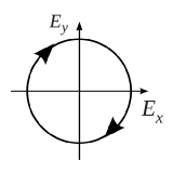
The circular polarization state is a special polarization state of elliptical polarization state, which satisfies the following conditions: 1) The field must have two orthogonal polarized components (such as x-direction and y-direction). 2) The two components mist have the same magnitude (Ex = Ey), 3) The two components must have a time-phase difference of multiples of 90 degrees.Thus, the field pattern can be written as:

And the polarization pattern can be drawn
Elliptical Polarization
The elliptical polarization is the general definition of the EMW polarization state whose field pattern can be expressed after make the simple math transformation of Ex and Ey :
Where,

Thus, the electric field pattern can be calculated as: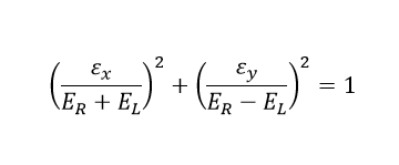
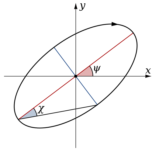
The above is elliptical polarization which can be seen as the superposition of two circular polarization possessing different magnitude and direction. And the general elliptical polarization pattern is shown below:
We have seen that the rates of change of different components of the E and B fields are related, that the electromagnetic wave is transverse, and that the wave propagates at speed c. We next show what Maxwell’s equations imply about the ratio of the E and B field magnitudes and the relative directions of the E and B fields.

We have arbitrarily taken the wave to be travelling in the +x-direction and chosen its phase so that the maximum field strength occurs at the origin at time t=0. We are justified in considering only sines and cosines in this way, and generalizing the results, because Fourier’s theorem implies, we can express any wave, including even square step functions, as a superposition of sines and cosines.
At any one specific point in space, the E field oscillates sinusoidally at angular frequency ω between +E0 and −E0 and similarly, the B field oscillates between +B0 and −B0. The amplitude of the wave is the maximum value of Ey(x,t). The period of oscillation T is the time required for a complete oscillation. The frequency f is the number of complete oscillations per unit of time, and is related to the angular frequency ω by ω=2πf. The wavelength λ is the distance covered by one complete cycle of the wave, and the wave number k is the number of wavelengths that fit into a distance of 2π in the units being used. These quantities are related in the same way as for a mechanical wave:

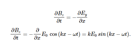
Because the solution for the B-field pattern of the wave propagates in the +x direction at the same speed c as the E-field pattern, it must be a function of k(x−ct)=kx−ωt. Thus, we conclude
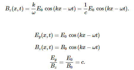
Therefore, the peaks of the E and B fields coincide, as do the troughs of the wave, and at each point, the E and B fields are in the same ratio equal to the speed of light c. The plane wave has the form
