Unit 2
Moment of Inertia
Moment of inertia of regular and composite solids
Moment of Inertia also called as "Angular Mass or Rotational Inertia" and "Second Moment of Area" is the inertia of a rotating body with respect to its rotation. Moment of Inertia applied to areas has no real meaning when examined by itself. It is merely a mathematical expression usually denoted by symbol I. However, when used in applications like flexural stresses in beams, it begins to have significance. The mathematical definition moment of inertia indicates that an area is divided into small parts dA, and each area is multiplied by the square of its moment arm about the reference axis.
I = ∫ ρ2 dA
The notation ρ (rho) corresponds to the coordinates of the center of differential area dA.
Step-By-Step Procedure in Solving for the Moment of Inertia of Composite or Irregular Shapes
1. Identify the x-axis and y-axis of the complex figure. If not given, create your axes by drawing the x-axis and y-axis on the boundaries of the figure.
2. Identify and divide the complex shape into basic shapes for easier computation of moment of inertia. When solving for the moment of inertia of a composite area, divide the composite area into basic geometric elements (rectangle, circle, triangle, etc) for which the moments of inertia are known. You can show the division by drawing solid or broken lines across the irregular shape. Label each basic shape to prevent confusion and miscalculations. An example is shown below.

3. Solve for the area and centroid of each basic shape by creating a tabular form of the solution. Obtain the distances from the axes of the centroid of the whole irregular shape before continuing to the computation of the moment of inertia. Always remember to subtract areas corresponding to holes. Refer to the article below for the computation of centroid distances.
- Calculating the Centroid of Compound Shapes Using the Method of Geometric Decomposition
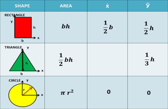
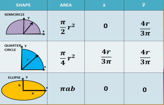
4. Once you obtained the location of the centroid from the axes, proceed to the calculation of the moment of inertia. Compute for the moment of inertia of each basic shape and refer for the formula for the basic shapes given below.
Below is the moment of inertia of basic shapes for its centroidal axis. To calculate the moment of inertia of a compound shape successfully, you must memorize the basic formula of the moment of inertia of basic geometric elements. These formulas are only applicable if the centroid of a basic shape coincides with the centroid of the irregular shape.
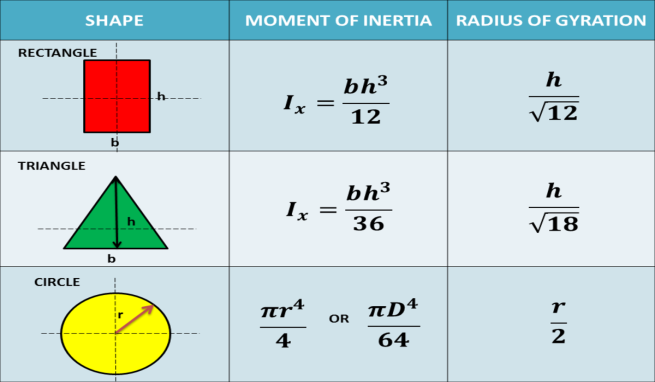
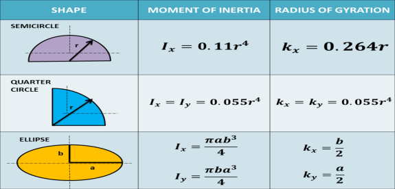
Moment of Inertia and Radius of Gyration of Basic Shapes
5. If the centroid of the basic shape does not coincide, it is necessary to transfer the moment of inertia from that axis to the axis where the centroid of the compound shape is located using the 'Transfer Formula for Moment of Inertia'.
The moment of inertia with respect to any axis in the plane of the area is equal to the moment of inertia with respect to a parallel centroidal axis plus a transfer term composed of the product of the area of a basic shape multiplied by the square of the distance between the axes. The Transfer formula for Moment of Inertia is given below.
6. Get the summation of the moment of inertia of all basic shapes using transfer formula
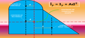
Transfer Formula of Moment of Inertia
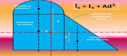
Concept of moment of inertia and second moment of area
Moment of inertia in physics quantitative measure of the rotational inertia of a body i.e the opposition that the body exhibits to having its speed of rotation about an axis altered by the application of a torque (turning force) The axis may be internal or external and may or may not be fixed. The moment of inertia (I), however, is always specified with respect to that axis and is defined as the sum of the products obtained by multiplying the mass of each particle of matter in a given body by the square of its distance from the axis. In calculating angular momentum for a rigid body, the moment of inertia is analogous to mass in linear momentum. For linear momentum, the momentum p is equal to the mass m times the velocity v; whereas for angular momentum, the angular momentum L is equal to the moment of inertia I times the angular velocity ω.
The figure shows two steel balls that are welded to a rod AB that is attached to a bar OQ at C. Neglecting the mass of AB and assuming that all particles of the mass m of each ball are concentrated at a distance r from OQ, the moment of inertia is given by I = 2mr2.

The unit of moment of inertia is a composite unit of measure. In the International System (SI), m is expressed in kilograms and r in metres, with I (moment of inertia) having the dimension kilogram-metre square. In the U.S. Customary system, m is in slugs (1 slug = 32.2 pounds) and r in feet, with I expressed in terms of slug-foot square.
The moment of inertia of anybody having a shape that can be described by a mathematical formula is commonly calculated by the integral calculus. The moment of inertia of the disk in the figure about OQ could be approximated by cutting it into a number of thin concentric rings, finding their masses, multiplying the masses by the squares of their distances from OQ, and adding up these products. Using the integral calculus, the summation process is carried out automatically; the answer is
I = (mR2)/2.
For a body with a mathematically indescribable shape, the moment of inertia can be obtained by experiment. One of the experimental procedures employs the relation between the period (time) of oscillation of a torsion pendulum and the moment of inertia of the suspended mass. If the disk in the figure were suspended by a wire OC fixed at O, it would oscillate about OC if twisted and released. The time for one complete oscillation would depend on the stiffness of the wire and the moment of inertia of the disk; the larger the inertia, the longer the time.
Second moment of area
The integral ∫ y2 dA defines the second moment of area I about an axis and can be obtained by considering a segment of area δA some distance y from the neutral axis, writing down an expression for its second moment of area and then summing all such strips that make up the section concerned, i.e. integrating. As indicated in the discussion of the general bending equation, the second moment of area is needed if we are to relate the stress produced in a beam to the applied bending moment.
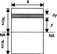
As an illustration of the derivation of a second moment of area from first principles, consider a rectangular cross-section of breadth b and depth d . For a layer of thickness δy a distance y from the neutral axis, which passes through the centroid, the second moment of area for the layer is:
Second moment of area of strip=y2δA=y2b δy
The total second moment of area for the section is thus:
Second moment of area=∫limits from −d/2 to d/2) y2bdy=bd3/12
Determine the second moment of area about the neutral axis of the I-section shown in Figure 5.4.28.
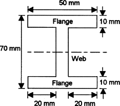
We can determine the second moment of area for such a section by determining the second moment of area for the entire rectangle containing the section and then subtracting the second moments of area for the rectangular pieces ‘missing’
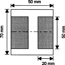
Thus for the rectangle containing the entire section, the second moment of area is given by I = bd3/12 = (50 × 703)/12 = 1.43 × 106mm4. Each of the ‘missing’ rectangles will have a second moment of area of (20 × 503)/12 = 0.21 × 106 mm4. Thus the second moment of area of the I-section is 1.43 × 10⁶ − 2 × 0.21 × 106 = 1.01 × 106mm4
Moment of Inertia for Composite Areas
A composite area consists of a series of simpler parts or shapes such as rectangle, triangle and circles. Provided the moment of inertia of each of these parts is known or can be determined about a common axis, then the moment of inertia for the composite area about this axis equals the algebraic sum of the moments of inertia for all its parts. Procedure for Analysis The moment of inertia for a composite area about a reference axis can be determined using the following steps 1. Using a sketch divided the area into its composite parts and indicates the perpendicular distance from the centroid of each part to the reference axis. 2.If the centroid axis for each part does not coincide with the reference axis, the parallel axis theorem, should be used to determine the moment of inertia about the reference axis. 3. The moment of inertia of entire area about the reference axis is determined by the summing the results of its composite parts about this axis. 4. If a composite part has an empty region(hole),its moment of inertia is found by subtracting the moment of inertia of this region from the moment of inertia of the entire part including the region.
Principal moments of inertia and principal axes
For a general three-dimensional body, it is always possible to find 3 mutually orthogonal axis (an x, y, z coordinate system) for which the products of inertia are zero, and the inertia matrix takes a diagonal form. In most problems, this would be the preferred system in which to formulate a problem. For a rotation about only one of this axis, the angular momentum vector is parallel to the angular velocity vector. For symmetric bodies, it may be obvious which axis is principle axis. However, for an irregular-shaped body this coordinate system may be difficult to determine by inspection; we will present a general method to determine these axes in the next section. But, if the body has symmetries with respect to some of the axis, then some of the products of inertia become zero and we can identify the principal axes.
For instance, if the body is symmetric with respect to the plane  then, we will have
  and
and  will be a principal axis. This can be shown by looking at the definition of the products of inertia.
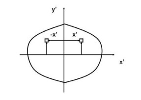
The integral for, say,  can be decomposed into two integrals for the two halves of the body at either side of the plane
  . The integrand on one half
  will be equal in magnitude and opposite in sign to the integrand on the other half (because
  will change sign). Therefore, the integrals over the two halves will cancel each other and the product of inertia
  will be zero. (As will the product of inertia
  ) Also, if the body is symmetric with respect to two planes passing through the center of mass which are orthogonal to the coordinate axis, then the tensor of inertia is diagonal, with
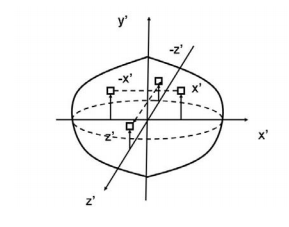
Another case of practical importance is when we consider axisymmetric bodies of revolution. In this case, if one of the axis coincides with the axis of symmetry, the tensor of inertia has a simple diagonal form. For an axisymmetric body, the moments of inertia about the two axis in the plane will be equal. Therefore, the moment about any axis in this plane is equal to one of these. And therefore, any axis in the plane is a principal axis. One can extend this to show that if the moment of inertia is equal about two axis in the plane (IP P = Ixx), whether or not they are orthogonal, then all axes in the plane are principal axes and the moment of inertia is the same about all of them. In its inertial properties, the body behaves like a circular cylinder.
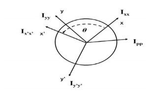
The tensor of inertia will take different forms when expressed in different axes. When the axes are such that the tensor of inertia is diagonal, then these axes are called the principal axes of inertia.
The Search for Principal Axes and Moments of Inertia as an Eigenvalue Problem
Three orthogonal principal axes of inertia always exist even though in bodies without symmetries their directions may not be obvious. To find the principle axis of a general body consider the body shown in the figure that rotates about an unknown principal axis. The total angular momentum vector is  in the direction of the principle axis. For rotation about the principal axis, the angular momentum and the angular velocity are in the same direction.
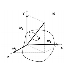
We seek a coordinate axes x, y and z, about which a rotation ωx, ωy and ωz, which is aligned with this coordinate direction, will be parallel to the angular momentum vector and related by the equation

We then express the general form for angular momentum vector in components along the x, y and z axis in term of the components of ω along these axes using the general form of the inertia tensor in the x, y, z system, we have

At this point in the process we know the inertia tensor in an arbitrary x, y, and z system and are seeking the special orientation of ω which will align the angular momentum HG with the angular velocity ω. Collecting terms from equation(11) on the left-hand side, we obtain

The structure of the solution for finding the principal axes of inertia and their magnitudes is a characteristic value problem. The three eigen values give the directions of the three principal axis, and the three eigenvectors give the moments of inertia with respect to each of these axis. In principal directions, the inertia tensor has the form

Polar moment of inertia / second moment of area
Polar Moment of Inertia is a measure of an object’s capacity to oppose or resist torsion when some amount of torque is applied to it on a specified axis. Torsion, on the other hand, is nothing but the twisting of an object due to an applied torque. Polar moment of inertia basically describes the cylindrical object’s (including its segments) resistance to torsional deformation when torque is applied in a plane that is parallel to the cross-section area or in a plane that is perpendicular to the object’s central axis.
If we put it in simple terms polar moment of inertia is the resistance offered by a beam or shaft when it is being distorted by torsion. This opposition usually arises from the cross-sectional area and it should be noted that it does not depend on the material composition. If the polar moment of inertia is of higher magnitude then the torsional resistance of the object will also be greater. More torque will be required to turn the shaft at an angle.
Nonetheless, it is one of the main aspects of the area moment of inertia and we can use the perpendicular axis theorem to link the two quantities.
Polar Moment Of Inertia Formula
Polar Moment of Inertia is also called the second polar moment of area. It is usually denoted by IZ. However, sometimes J or JZ is also used. Polar Moment of Inertia can be represented mathematically with the given formula;
I or J = r2 dA
Here,
r = distance to the element dA.
Units
The dimension unit of polar moment of inertia is length to the power of four (L4); The SI unit of this property is, meters to the fourth power (m4). In the imperial unit system, it is inches to the fourth power (in4).
Types of Cross-section Polar Moment of Inertia
There are three main types of cross-section polar moment of inertia. They are as follows.
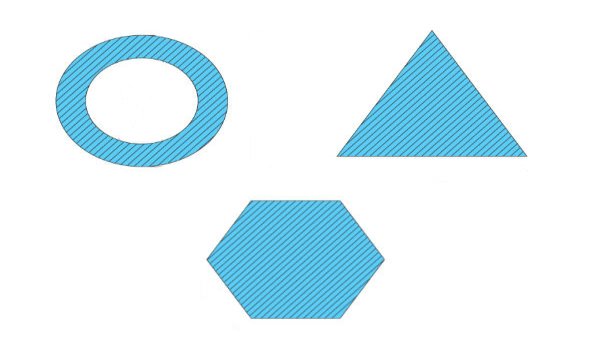
1. Hollow Shaft
To determine the polar moment of inertia we use;
Jhollow = π(R04–R14)/2
R1 and Ro = inner and outer radius of the hollow shaft.
2. Thin-Walled Shaft
To determine the polar moment of inertia we use;
Jthin = 2πt [R0+Ri/2]3
t = thickness of the thin-walled shaft.
3. Solid Circular Shaft
To determine the polar moment of inertia we use the following formula;
Jsolid = πR4/2
R = radius of the circular shaft.
Uses and Limitations
Generally, the second polar moment of area is used in determining the angular displacement of a body that is subjected to torque or to calculate the torsion force on a circular body. As for the limitation, the polar moment of inertia is not suitable for analysing shafts and beams with non-circular cross-sections. This is mainly because objects with non-circular cross-sections tend to warp when torque is applied and it further leads to out-of-plane deformations.
Product of inertia
The area product of inertia is defined as
The x and y terms inside the integral denote the centroidal position of the differential area measured from the y and x axes, respectively. Similar to moments of inertia discussed previously, the value of product of inertia depends on the position and orientation of selected axes. It is possible for the product of inertia to have a positive, negative, or even a zero value.
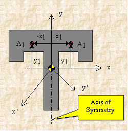
If, for example, either x or y represents an axis of symmetry, then the product of inertia Ixy would be zero. To see why this is the case, take a look at the figure to the right. Consider the small area A1 to the right of y axis at the distance of x1. Then consider a similar area to the left of this axis of symmetry at the distance of -x1. Since both areas are at the same vertical position from the x-axis, they have the same value of y. The contribution from the left area is -x1yA1 and that from the right is x1yA1 which add up to zero. Since every point on one side of the axis of symmetry has an equal counterpart on the other side, the total value of the integral would be zero.
However, if we were to consider the product of inertia with respect to the x' and y' axes, then Ix'y' would not be zero. We will have more discussion about the product of inertia in the section on principal axes.
Coplanar non-concurrent force system and Analysis of Plane trusses and frames:
Equation of equilibrium:
- A body is said to be in equilibrium if the resultant of all forces acting on it is zero.
- When the resultant of all the forces acting on the particle is zero, then, the particle is in equilibrium.
- If the resultant force acting on a particle is zero (or if particle is in equilibrium state) the, particle will remain at rest condition if it is originally at rest; or particle will move with constant speed in a straight line if it is originally in motion.
Condition for Equilibrium: R = 0 {  }
}
∑M = 0
Concept of load carrying mechanism in trusses and frames – internal (axial) forces, two force and multi force members
Trusses are simply defined as triangulation of members to make the stabilized structure. Triangulation is the stable configuration mathematically. Generally, a truss has the members called as top chord, bottom chord, vertical chord and diagonal chord. The main functions of the trusses are:
- Carrying the loads from the over structures
- Providing adequate lateral stability to the entire structure
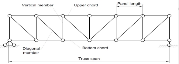
There are some basic assumptions in the designing process. It should be clarified that the construction of the trusses should conform with the design assumptions to avoid the unwanted failures due to the dispersion of the forces and loads. Following are the assumptions in truss design.
- Truss members will carry only the axial forces
- The nodes i.e the connections of the members are designed as pinned joints so that moments won’t be transferred to the members of the truss
- All the external loads and the reactions are act only on the nodes
- Generally, the truss should be in a plane.
Typically the members of the trusses are made as I sections, angles, T sections, Tube sections, Square sections and channel sections. I sections are more preferable as a optimized section in terms of the structural forces.
TYPES OF TRUSSES
- Simple truss – indicates a single triangular truss. These trusses are most often used as the roof trusses.
- Planar truss – as the name implies it is a two dimensional truss. If all the members and the nodes are in a planar surface, then this truss is a planar truss.
- Space frame truss – Contrast to planar truss, the members and the nodes are located in the three dimensional space. Electrical and telecom towers are the one of the simplest example that we are seeing in the day to day life.
FORMS OF TRUSSES
1. Pratt truss

Pratt truss form for the loads in gravity direction

Pratt truss form for the uplift loads(loads opposite to gravity)
2. Warren truss

3. North light truss

4. Vierendeel truss

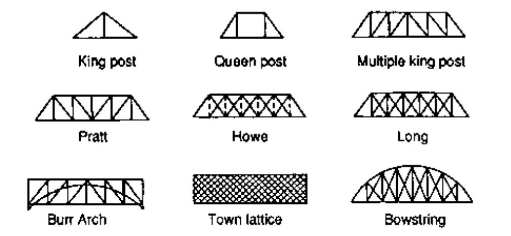
King post truss, Bowstring truss, Queen post truss, Flat truss, Lenticular truss are some other forms of trusses in the use of the industry.
Rigid or perfect Truss
Truss:-
A Rigid structure formed by connecting various two force members to each other by using pin joint..
Plane truss: When all member of the truss lies in one plane, Then truss is known as plane truss
Rigid truss:- A truss which do not collapse when external Load is applied on it.
Simple truss:-The structure formed by basic triangle made by Connecting various members are called simple truss
Classification of Truss:-
Perfect truss Imperfect (unstable)
(Stable) (n  2j R)
2j R)
(n=2j- R) over stable Deficient Truss,
(Redundant)
(n< 2 j – R) (n < 2 j-R)
- Perfect truss: A truss which does not collaspe under the action of
Load is called perfect truss.
Condition : n = 2 j-R
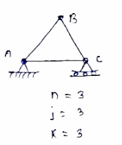
n= no. Of member
j = no of joints
R = no. Of reaction
In truss ABC, n = 3 & 2 j- R+3
So it is perfect truss
- Imperfect truss: A truss which does not collapse under the load is called Imperfect or unstable truss.
Here n 2j -R
2j -R
Over stable (Redundant Truss)
A truss in which n > 2j- R, Then it is over stable truss.
Diagram


Deficient truss
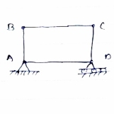
It is a truss in which
N <2 j-R.
- Cantilever Truss:
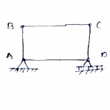
A truss which is fixed on one side & free of Other end is called as cantilever truss.
.
Diagram
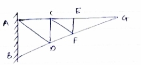
*Assumption made in the analysis:-
1) Given truss a perfect truss
2) The truss member are connected by joints only.
3) External loads are acting at the joints only.
4) All members are two force members.
5) The self- weight of members is neglected.
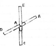
1) If
When four members are connected
At Engile joint in such a way
That opposite members lie in a
Single straight line
&
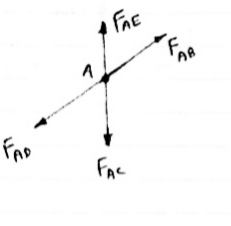
There is No external load acting at the joint Then Forces in the opposite members Are equal.
FAE = FAC & FAB = FAD.
2) If There are only there members at a joint and Out of there, two are collinear and is inclined To first two or lar to first members, With no external load at joint,
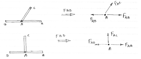
Then,
a) Forces in the two opposite ( co- linear) members are equal.
l.e FAD = FAB
b) The force in the inclined member is zero
l.e FAC =0
c) Force in the perpendicular member is zero
FAc = 0
4) If There are two member at a joint with one Member Horzintal & one vertical & there is no external load of joint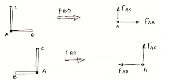
Then, Both member are zero force member,
Angle FAB=0
FAC =0
5) If there are only two members at joint With- one member vertical & other inclined & there is no external load of joint,

Then both members are zero force members
I.e. FAB = 0 & FAC =0
One member Horizontal & other inclined and There is No external load at joint.

Then both members are zero force members
FAB = 0 and FAC =0
6) if there are only two members at a joint with one member Horizontal & other inclined and there is no External load at joint
Diagram

Then both members are zero force member
FAB=0 and FAC = 0
Determination of Axial forces in the members of truss
A truss is a structure composed of straight, slender members connected at their ends by frictionless pins or hinges. A truss can be categorized as simple, compound, or complex. A simple truss is one constructed by first arranging three slender members to form a base triangular cell. Additional joints can be formed in the truss by subsequently adding two members at a time to the base cell, as shown in Figure 2.3 a. A compound truss consists of two or more simple trusses joined together, as shown in Figure 2.3 b. A complex truss is neither simple nor compound, as shown in Figure 2.3 c; its analysis is more rigorous than those of the previously stated trusses.
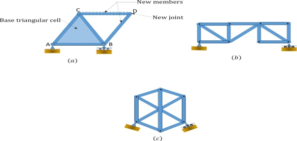 Classification of trusses
Types of Trusses
The following are examples of different types of trusses for bridges and roofs.
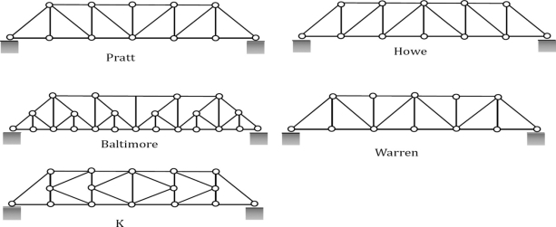
Fig. 2.3(A). Commonly used bridge trusses.
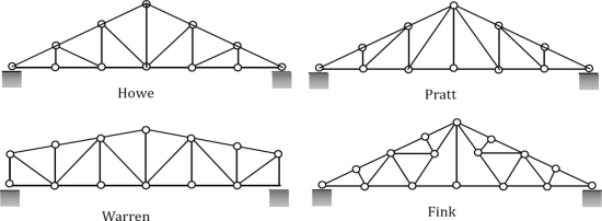
Fig. 2.3(B). Commonly used roof trusses.
The conditions of determinacy, indeterminacy, and instability of trusses can be stated as follows:

Where
m = number of members.
r = number of support reactions.
j = number of joints.
Assumptions in Truss Analysis
1. Members are connected at their ends by frictionless pins.
2. Members are straight and, therefore, are subjected only to axial forces.
3. Members’ deformation under loads are negligible and of insignificant magnitude to cause appreciable changes in the geometry of the structure.
4. Loads are applied only at the joints due to the arrangement of members.
Joint Identification and Member Force Notation
Truss joints can be identified using alphabets or numbers, depending on the preference of the analyst. However, consistency must be maintained in the chosen way of identification to avoid confusion during analysis. A bar force can be represented by any letter (F or N or S), with two subscripts designating the member. For example, the member force FAB in the truss shown in Figure is the force in the member connecting joints A and B.

Fig. 2.3(C). Joint identification (a) and bar force (b).
Analysis of plane trusses by Method of joints and Method of sections
Method of Joints
Method of joint: This method involves isolating each joint of the truss and considering the equilibrium of the joint when determining the member axial force. Two equations used in determining the member axial forces are ∑ Fx = 0 and ∑ Fy = 0. Joints are isolated consecutively for analysis based on the principle that the number of the unknown member axial forces should never be more than two in the joint under consideration in a plane trust.
Analysis of Trusses by Method of Joint
This method is based on the principle that if a structural system constitutes a body in equilibrium, then any joint in that system is also in equilibrium and, thus, can be isolated from the entire system and analyzed using the conditions of equilibrium. The method of joint involves successively isolating each joint in a truss system and determining the axial forces in the members meeting at the joint by applying the equations of equilibrium. The detailed procedure for analysis by this method is stated below.
Procedure for Analysis
•Verify the stability and determinacy of the structure. If the truss is stable and determinate, then proceed to the next step.
•Determine the support reactions in the truss.
•Identify the zero-force members in the system. This will immeasurably reduce the computational efforts involved in the analysis.
•Select a joint to analyse. At no instance should there be more than two unknown member forces in the analysed joint.
•Draw the isolated free-body diagram of the selected joint, and indicate the axial forces in all members meeting at the joint as tensile (i.e. as pulling away from the joint). If this initial assumption is wrong, the determined member axial force will be negative in the analysis, meaning that the member is in compression and not in tension.
•Apply the two equations Σ Fx = 0 and Σ Fy = 0 to determine the member axial forces.
•Continue the analysis by proceeding to the next joint with two or fewer unknown member forces.

Method of Sections
Method of section: This method entails passing an imaginary section through the truss to divide it into two sections. The member forces are determined by considering the equilibrium of the part of the truss on either side of the section. This method is advantageous when the axial forces in specific members are required in a truss with several members.

Analysis of Trusses by Method of Section
Sometimes, determining the axial force in specific members of a truss system by the method of joint can be very involving and cumbersome, especially when the system consists of several members. In such instances, using the method of section can be timesaving and, thus, preferable. This method involves passing an imaginary section through the truss so that it divides the system into two parts and cuts through members whose axial forces are desired. Member axial forces are then determined using the conditions of equilibrium. The detailed procedure for analysis by this method is presented below.
Procedure for Analysis of Trusses by Method of Section
•Check the stability and determinacy of the structure. If the truss is stable and determinate, then proceed to the next step.
•Determine the support reactions in the truss.
•Make an imaginary cut through the structure so that it includes the members whose axial forces are desired. The imaginary cut divides the truss into two parts.
•Apply forces to each part of the truss to keep it in equilibrium.
•Select either part of the truss for the determination of member forces.
•Apply the conditions of equilibrium to determine the member axial forces.