Unit 2
Internal Combustion Engines
An I.C engine consists of a cylinder and piston. Piston is connected to the crank-shaft through connecting Rod. At the head of the cylinder intake valve and exhaust valve is present that are operated by a camshaft.
For SI engine a spark plug is present and for CI engine a fuel spray nozzle is present. Cooling system (water jacket) is provided outside the cylinder. Lubricant-oil system is provided along with the piston. There are some piston rings to avoid wear and tear of the cylinder and piston.
For two strokes engine valves are eliminated by ports. There are some accessories with the engine like carburettor, injection system, cooling system, lub oil system, catalytic converter, and many others.
S.I Engine: SI Stands for Spark Ignition. This is one kind of IC (Internal Combustion) engine.
There are four processes in engine.
- Intake or suction
- Compression
- Power or combustion
- Exhaust


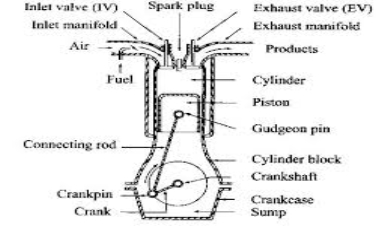
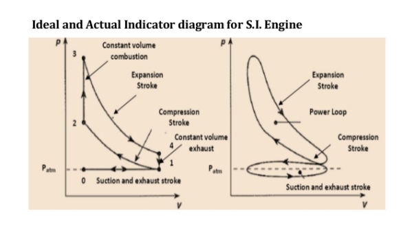
Process 0-1 (Suction stroke)
At the start of cycle the piston moves from TDC to BDC. The inlet valve (I.V.) is opened automatically by valve operating mechanism at the start of this process. Due to increase in volume inside the cylinder, a slight vacuum is created and, the fresh charge i.e. mixture of air and petrol prepared in Carburettor is sucked inside the cylinder through inlet valve. At the end of stroke, the piston reaches BDC position, total volume of cylinder is filled with fresh charge and inlet valve is closed. Theoretically, the charge is filled at constant pressure P1 and it occupies the total volume of cylinder V1.
Process 1-2 (Compression stroke)
During this stroke, both the valves remain closed and piston is moved from BDC to TDC by the force of crank. As the piston moves up, volume of cylinder shrinks and the fresh charge is compressed to a higher pressure P2 and volume V2 equal to clearance volume. Theoretically, this process is adiabatic compression process. Temperature of fresh charge is also raised in compression from T1 to T2.
Process 2-3 (heat addition or constant volume combustion)
This process is actually a constant volume heat addition process. At point 2, spark plug ignites and starts the combustion of already compressed, high temperature charge. Due to very favourable conditions of combustion, combustion of charge and heat release takes place in no time and pressure & temperature further shoots up to P3 and T3. Theoretically the volume remains constant from 2to 3. So V2=V3=VC=Clearance Volume.
Process 3-4 (expansion or working stroke)
This is the process or stroke of piston in which positive work is obtained. The burnt gases at high pressure and high temperature at point 3 expand and push the piston again from TDC to BDC, thus doing work on the piston. This work is given to output shaft of engine through connecting rod and crank shaft. A small portion of it is stored in the heavy rotating flywheel mounted on crankshaft, which is used in movement of piston in three other idle stroke i.e. Suction, Compression and Exhaust. When piston reaches BDC, cylindrical total volume is filled with comparatively lower pressure and temperature burnt gases or smoke. At this point 4, the exhaust valve (EV) opens.
Process 4-1 (heat rejection or constant volume exhaust)
In this process, as soon as the exhaust valve is opened at point 4, the burnt gases start escaping to atmosphere and their pressure reduces to atmospheric pressure P1. Theoretically, this process happens in no time and escaping of exhaust gases take away some heat from the engine.
Process 1-0 (exhaust stroke)
This stroke is just opposite to suction stroke. Piston moves from BDC to TDC and pushes away or sweeps the remaining burnt gases out through E.V. As the piston reaches TDC most of burnt gases escape and E.V. Is closed. One cycle of the engine completes here. Simultaneously, the I.V. Opens and next cycle starts.
In this way, piston goes on moving or reciprocating from TDC to BDC and BDC to TDC with a high speed and engine produces power continuously by burning of petrol or gas etc. The power output and RPM of engine can be easily controlled by a throttling valve fitted in the passage of air intake or in the carburettor where fuel and air are mixed together in the right proportion..
In the exhaust phase, the piston goes upward and the burnt gases go away through the exhaust valve.
C.I Engine:A diesel engine is called compression Ignition engine because here the conditions of combustion or ignition are achieved only by compression of air to a very high pressure.
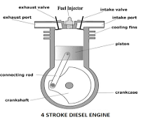
There is no spark plug to initiate the combustion, but in place of that a fuel injector is there, which injects and atomizes the fuel. Diesel at a very high pressure in very hot compressed air after compression stroke in engine. Due to high pressure and temperature above the ignition temperature, fuel atomization, evaporation and self-ignition take place.
The rest of the working of Diesel Engine is same as that of Petrol or Gasoline Engine. Here also one complete cycle is comprised of all the processes of Diesel cycle along with suction of fresh air and exhaust of burnt gases. To carry out all these processes, here also normally 4 strokes of piston are required. So, it is called a 4-stroke Diesel Engine or C.I Engine.

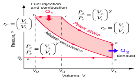
Process e-a (suction stroke)
At the start of cycle, the piston moves from TDC to BDC and inlet valve is opened at the start of process at point e. Due to increase in volume of cylinder by the movement of piston, the fresh air from atmosphere enters the cylinder and occupies all the space inside the cylinder until piston reaches BDC. At the point a, air filled in cylinder is at volume V1 and its pressure & temperature are theoretically same as that of outside atmosphere. Here inlet valve is closed and cylinder becomes a closed thermodynamic system.
Process a-b (compression stroke)
In this stroke, piston moves from BDC to TDC by the force of crank. As both valves are closed, the air sucked in previous stroke is compressed to the clearance volume. Here in Diesel engine the compression ratio rcwhich is the ratio of total volume V1 to clearance volume V2 is very high as compared to SI Engine. So, naturally the rise in pressure and temperature of air at the end of compression stroke is also more. The range of rc (compression ratio)in Diesel Engine is 15 to 22. Theoretically, the compression process is adiabatic & isentropic Compression.
Process b-c (heat addition or fuel injector)
This process is actually a constant pressure heat addition process or a mix of constant volume and constant pressure process as in case of high speed diesel engine. At the point b the fuel injector injects a fix quantity of fuel in very hot & compressed air compressed to the clearance volume. Due to that fuel spray ignites itself thus releasing of heat in the cylinder. As this heat addition process is slow, piston moves back to some distance from TDC to point c shown in fig and the volume increases which nullifies the effect of increase in pressure due to heat addition. Pressure remains constant theoretically upto point c, where the injector stops injection of fuel and so the addition of heat. Point c is also called cut-off point. A part of piston stroke from b to c takes place along with this process and the burning fuel plus air mixture expand and push the piston producing a positive work.
Process c-d (expansion stroke or power stroke)
Actually the complete expansion stroke is from point b to point d but a part of it is along the previous heat addition process b-c. After point c heat addition stops and the hot and high pressure burnt gases expand at the cost of their own internal energy and produce positive work by pushing the piston to BDC. This stroke is called working stroke as here piston moves the crankshaft and give mechanical energy. Major part of this energy is given to output shaft and a small portion is stored in heavy flywheel in the form of its rotational kinetic energy and used up during idle strokes of piston i.e. Suction, Compression & Exhaust.
Process d-a (heat rejection)
This process takes place at constant volume and heat is rejected directly by escaping of some of burnt gases due to pressure difference inside and outside the engine as soon as exhaust valve opens at point d i.e. just at the end of expansion or working stroke. Theoretically, piston remains at BDC and gases escape in no time, taking away some heat from the engine. Pressure inside the cylinder reduces to atmospheric pressure.
Process a-e (exhaust stroke)
In this process or stroke, piston is moved by crank from BDC to TDC. As the exhaust valve remains open during this stroke, piston displaces or sweeps out the burnt gases through it and only a small fraction of gases remain in the clearance volume finally. The piston reaches TDC and the cycle completes as the initial conditions are again reached. At this point, exhaust valve closes and inlet valve opens and next cycle starts.
In this way piston moves or reciprocates from TDC to BDC and again from BDC to TDC with a high speed and engine produces power continuously by burning of air and fuel mixture. The power output and RPM of engine here can be controlled by controlling the quantity of fuel injected only. There is no restriction on the quantity of air sucked by engine. There is a mechanical or electric control on the fuel injection depending on fuel injection system used. When more power is required more quantity of fuel is injected and when less power is required accordingly fuel supply is reduced. There is no control on the quantity of air so air sucked remains more or less same. In this way only the quality of combustible mixture changes in different conditions of loading and so Quality Governing is used in CI Engine.
Two stroke cycles
In two stroke engine the working cycle is completed in two stroke of the piston or one revolution of crankshaft. This is achieved by carried out suction and compression in one stroke expansion and exhaust in the second stroke.
A two stroke engine has port instead of valves. Opening and closing of the port are controlled by the piston
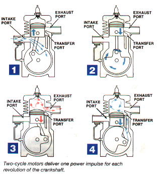
Following are the process in two stroke engine
1) Suction stroke: In this stroke piston while moving downward BDC (bottom dead centre) both the transfer port and exhaust port are open. The fresh fuel air mixture flows into the engine cylinder from crankcase.
2) Compression stroke: In this stroke, the piston while moving upwards, first cover the transfer port then exhausts port. After that fuel is compressed as the piston moves upwards. In this stage the inlet port opens and fresh air fuel mixture enters into crankcase.
3) Expansion stroke:During compression stroke the piston reached TDC (top dead centre) the charge is ignited with the help of spark plug .It suddenly increases the pressure and temperature of the product of combustion and volume remain constant. Due to rise in pressure the piston is pushed downwards with greater pressure .During the expansion some of the heat energy is produces and transform into mechanical work.
4) Exhaust stroke: In this stroke piston move downward and exhaust port is opened. The burned gases are exhaust from the engine cylinder through exhaust port into the atmosphere.
The two-stroke engines lighter, simpler and less expensive to manufacture. Two-stroke engines also have the potential to pack about twice the power into the same space because there are twice as many power strokes per revolution. The combination of light weight and twice the power gives two-stroke engines a great power-to-weight ratio compared to many four-stroke engine designs.
Four stroke cycles
In four stroke engine the working cycle is completed in four stroke of the piston or two revolution of crankshaft. This is achieved by carried out suction in one stroke and compression in second stroke, expansion in third stroke and exhaust in the fourth stroke. They have inlet and exhaust valve. Suction and compression in one revolution of crankshaft, expansion and exhaust in second revolution of crankshaft.
Following are the process in four stroke engine;
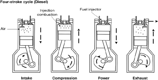
1) Suction stroke: In this stroke while piston moving downward BDC (bottom dead centre) inlet valve opens and pure air is sucked into the cylinder.
2) Compression stroke: In this stroke, the piston while moving from BDC to TDC, the inlet and outlet valve are closed. The compressed start as piston moves upwards. Which increase pressure and temperature .this complete one revolution of crankshaft
3) Expansion stroke: just before the piston reached the top dead centre fuel oil injected in the form of very fine spray into the cylinder .at this point temperature of the compressed air is sufficiently high to ignite the fuel which suddenly increases the pressure and temperature of combustion products. Due to increase in pressure the piston is pushed down with a great force.
4) Exhaust stroke: In this stroke exhaust valve open as piston move from BDC to TDC .This movement of the piston moves up and pushed out the burned gases to atmosphere from the engine cylinder
Multi point fuel injection
Fuel injection is a method or system for admitting fuel into the internal combustion engine. From early 1940s many injection system like single-point injection, continuous injection are introduced in the market by the different companies. But presently the most used injection system are MPFI in petrol engine and CRDI in diesel engine.
MPFI (Multi point Fuel Injection) System
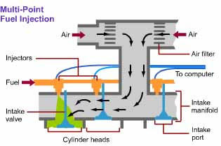
Multi Point Fuel Injection System
Petrol vehicles uses device called carburettor for supplying the air fuel mixture in correct ratio to cylinders in all rpm ranges. Due to construction of the carburettor is relatively simple; it has been used almost exclusively on gasoline engines in the past. However presently we need cleaner exhaust emission system, more economical fuel consumption, improved drivability, etc.
So in order to get all these, we need a carburettor that must have various devices to do the above functions, making it more complex system. So In place of the carburettor, therefore, the MPFI (multi point fuel injection) system is used, assuring proper air fuel ratio to the engine by electrically injecting fuel in accordance with various driving condition.
Multi point fuel injection system injects fuel into the intake ports just upstream of each cylinder’s intake valve, rather than at the central point within the intake manifold.
Multi point fuel injection systems are of three types, first is BATCHED in which fuel is injected to the cylinders in groups, without precisely bringing together to any particular cylinder’s intake stroke, the second one is simultaneous in which fuel is injected at the same time to all the cylinders and the third one is sequential in which injection is timed to coincide with each cylinder’s intake stroke.
ADVANTAGES OF MULTI POINT FUEL INJECTION SYSTEM
- More uniform air-fuel mixture will be supplied to each cylinder hence the difference in power developed in each cylinder is minimum.
- The vibrations produced in MPFI engines is very less, due to this life of the engine component is increased.
- No need to crank the engine twice or thrice in case of cold starting as happen in the carburetor system.
- Immediate response, in case of sudden acceleration and deceleration.
- The mileage of the vehicle is improved.
- More accurate amount of air-fuel mixture will be supplied in this injection system. As a result complete combustion will take place. This leads to effective utilization of fuel supplied and hence low emission level.
Carbureted engines
The fuel/air mixture meets in the carburetor. The mixture then goes to each cylinder through the air intakes. In the fuel injected engine, the fuel and air do not mix until they reach the cylinder. Since fuel injection systems shoot fuel directly into the cylinders, they are easier to flood (too much fuel) when starting. For this reason, starting procedures for fuel injected engines vary a good bit depending on the aircraft/engine combination. Carbureted engines undoubtedly take less talent to get started.
Cruising though they are easier to start, carbureted engines are less efficient during flight. Since the fuel/air mixture in carbureted systems meet at the carburetor, the mixture is less precise for each cylinder. Fuel injectors are calibrated to force the same amount of fuel into each cylinder. Because of their precision, most fuel injection systems also permit monitoring of each cylinder’s EGT (Exhaust Gas Temperature). EGT probes on each cylinder allow the pilot to create the ideal engine performance; saving fuel, as well as reducing wear on the engine. For these reasons, as well as many others, fuel injected engines are standard on most new aircraft.
Carbureted systems are simple: fewer parts, less complexity, less maintenance. In fact, our carbureted Cessna do not need fuel pumps since the fuel tanks are high (in the wings) and push the fuel all the way to the carburetor. One thing carbureted engines do need is carb heat. When activated, carb heat allows air to flow around the exhaust (to heat up) and then into the carburetor — bypassing the induction filter. The hot air melts/prevents ice buildup around the throttle valve. Fuel injected engines do not need carb heat, but they do need electric fuel pumps as a starting flow, as well as a backup for the engine-driven fuel pump.
Fuel Pump
A Fuel Pump is a mechanical or electrical device fitted aside a vehicle’s engine. The Fuel Pump is responsible for pumping gas to the engine from the fuel tank. The fuel tank is usually located at a different position from the engine. Therefore, a Fuel Pump is required mostly in cars or other vehicles that have internal combustion engines in them to pump up the gas from the fuel tank over to the engine. The Fuel Pump, along with a carburetor works in order to supply the fuel to the fuel tank.
A vehicle that contains an internal combustion engine requires a Fuel Pump for the easy working of the engine. The latest non-gravity feed design engines need it in order to facilitate the easy flow of fuel from the fuel tank to the engine. The Fuel Pump provides fuel to the carburetor at a very low pressure. If the engine has a fuel injection system, then the pump provides fuel to the engine at a high pressure. A Fuel Pump can be of two types – mechanical and electric. Mechanical fuel pumps were used in carbureted engines; however, after the implementation of the electronic fuel injection systems, the electric mechanical pump is used in the modern day automobiles.
Fuel injection system
For the engine to run smoothly and efficiently it needs to be provided with the right quantity of fuel /air mixture according to its wide range of demands.
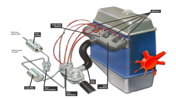
Petrol-engine cars use indirect fuel injection. A fuel pump sends the petrol to the engine bay, and it is then injected into the inlet manifold by an injector. There is either a separate injector for each cylinder or one or two injectors into the inlet manifold.
Traditionally, the fuel/air mixture is controlled by the Carburetor an instrument that is by no means perfect.
Its major disadvantage is that a single carburettor supplying a four- cylinder engine cannot give each cylinder precisely the same fuel/air mixture because some of the cylinders are further away from the carburettor than others.
One solution is to fit twin-carburettors, but these are difficult to tune correctly. Instead, many cars are now being fitted with fuel-injected engines where the fuel is delivered in precise bursts. Engines so equipped are usually more efficient and more powerful than carburetted ones, and they can also be more economical, as well as having less poisonous emission.
Diesel fuel injection
The fuel injection system in petrol engine cars is always indirect, petrol being injected into the inlet manifold or inlet port rather than directly into the combustion chambers. This ensures that the fuel is well mixed with the air before it enters the chamber.
Many diesel engines, however, use direct injection in which the diesel is injected directly into the cylinder filled with compressed air. Others use indirect injection in which the diesel fuel is injected into the specially shaped pre-combustion chamber which has a narrow passage connecting it to the cylinder head.
Only air is drawn into the cylinder. It is heated so much by compression that atomized fuel injected at the end of the compression stroke self-ignites.
Basic injection
All modern petrol injection systems use indirect injection. A special pump sends the fuel under pressure from the fuel tank to the engine bay where, still under pressure, it is distributed individually to each cylinder. Depending on the particular system, the fuel is fired into either the inlet manifold or the inlet port via an injector. This works much like the spray nozzle of a hose, ensuring that the fuel comes out as a fine mist. The fuel mixes with the air passing through the inlet manifold or port and the fuel/air mixture enters the combustion chamber.
Some cars have multi-point fuel injection where each cylinder is fed by its own injector. This is complex and can be expensive. It's more common to have single-point injection where a single injector feeds all the cylinders, or to have one injector to every two cylinders.
Injectors
The injectors through which the fuel is sprayed are screwed, nozzle-first, into either the inlet manifold or the cylinder head and are angled so that the spray of fuel is fired towards the inlet valve. The injectors are one of two types, depending on the injection system. The first system uses continuous injection where the fuel is squirted into the inlet port all the time the engine is running. The injector simply acts as a spray nozzle to break up the fuel into a fine spray - it doesn't actually control the fuel flow. The amount of fuel sprayed is increased or decreased by a mechanical or electrical control unit - in other words, it is just like turning a tap on and off.The other popular system is timed injection (pulsed injection) where the fuel is delivered in bursts to coincide with the induction stroke of the cylinder. Aswith continuous injection, timed injection can also be controlled either mechanically or electronically. The earliest systems were mechanically controlled. They are often called petrol injection (PI for short) and the fuel flow is controlled by a mechanical regulator assembly. These systems suffer from the drawbacks of being mechanically complex and having poor response to backing off the throttle. Mechanical systems have now been largely superseded by electronic fuel injection (known as EFi for short). This is thanks to the increasing reliability and decreasing costs of electronic control systems.
COOLING AND LUBRICATION SYSTEM
Need for cooling system
The cooling system has four primary functions. These functions are as follows:
1. Remove excess heat from the engine.
2. Maintain a constant engine operating temperature.
3. Increase the temperature of a cold engine as quickly as possible.
4. Provide a means for heater operation (warming the passenger compartment).
Types of cooling system:
The different Types of cooling system are
1. Air cooling system
2. Liquid cooling system
3. Forced circulation system
4. Pressure cooling system
Air-Cooled System:
The simplest type of cooling is the air-cooled, or direct, method in which the heat is drawn off by moving air in direct contact with the engine Several fundamental principles of cooling are embodied in this type of engine cooling. The rate of the cooling is dependent upon the following:
1. The area exposed to the cooling medium
2. The heat conductivity of the metal used & the volume of the metal or its size in cross section
3. The amount of air flowing over the heated surfaces
4. The difference in temperature between the exposed metal surfaces and the cooling air
LIQUID-COOLED SYSTEM
Nearly all multicylinder engines used in automotive, construction, and material-handling equipment use a liquid-cooled system. Any liquid used in this type of system is called a COOLANT.
A simple liquid-cooled system consists of a radiator, coolant pump, piping, fan, thermostat, and a system of water jackets and passages in the cylinder head and block through which the coolant circulates. Some vehicles are equipped with a coolant distribution tube inside the cooling passages that directs additional coolant to the points where temperatures are highest. Cooling of the engine parts is accomplished by keeping the coolant circulating and in contact with the metal surfaces to be cooled. The operation of a liquid- cooled system is as follows: The pump draws the coolant from the bottom of the radiator, forcing the coolant through the water jackets and passages, and ejects it into the upper radiator tank. The coolant then passes through a set of tubes to the bottom of the radiator from which the cooling cycle begins. The radiator is situated in front of a fan that is driven either by the water pump or an electric motor. The fan ensures airflow through the radiator at times when there is no vehicle motion. The downward flow of coolant through the radiator creates what is known as a thermo siphon action. This simply means that as the coolant is heated in the jackets of the engine, it expands. As it expands, it becomes less dense and therefore lighter. This causes it to flow out of the top outlet of the engine and into the top tank of the radiator. As the coolant is cooled in the radiator, it again becomes more dense and heavier. This causes the coolant to settle to the bottom tank of the radiator. The heating in the engine and the cooling in the radiator therefore create a natural circulation that aids the water pump. The amount of engine heat that must be removed by the cooling system is much greater than is generally realized. To handle this heat load, it may be necessary for the cooling system in some engine to circulate 4,000 to 10,000 gallons of coolant per hour. The water passages, the size of the pump and radiator, and other details are so designed as to maintain the working parts of the engine at the most efficient temperature within the limitation imposed by the coolant.
Pressure cooling system
Radiator Pressure Cap
The radiator pressure cap is used on nearly all of the modern engines. The radiator cap locks onto the radiator tank filler neck Rubber or metal seals make the cap-to-neck joint airtight. The functions of the pressure cap are as follows:
1. Seals the top of the radiator tiller neck to prevent leakage.
2. Pressurizes system to raise boiling point of coolant.
3. Relieves excess pressure to protect against system damage.
4. In a closed system, it allows coolant flow into and from the coolant reservoir.
The radiator cap pressure valve consists of a spring- loaded disc that contacts the filler neck. The spring pushes the valve into the neck to form a seal. Under pressure, the boiling point of water increases. Normally water boils at 212°F. However, for every pound of pressure increase, the boiling point goes up 3°F. Typical radiator cap pressure is 12 to 16 psi. This raises the boiling point of the engine coolant to about 250°F to 260°F. Many surfaces inside the water jackets can be above 212°F. If the engine overheats and the pressure exceeds the cap rating, the pressure valve opens. Excess pressure forces coolant out of the overflow tube and into the reservoir or onto the ground. This prevents high pressure from rupturing the radiator, gaskets, seals, or hoses. The radiator cap vacuum valve opens to allow reverse flow back into the radiator when the coolant temperature drops after engine operation. It is a smaller valve located in the centre, bottom of the cap. The cooling and contraction of the coolant and air in the system could decrease coolant volume and pressure. Outside atmospheric pressure could then crush inward on the hoses and radiator. Without a cap vacuum or vent valve, the radiator hose and radiator could collapse
ENGINE LUBRICATINGSYSTEMS
All internal combustion engines are equipped within internal lubricating system. Without lubrication, an engine quickly overheats and its working parts seize due to excessive friction. All moving parts must be adequately lubricated to assure maximum wear and long engine life.
PURPOSES OF LUBRICATION
The functions of an engine lubrication system are as follows: Reduces friction and wear between moving parts. Helps transfer heat and cool engine parts. Cleans the inside of the engine by removing contaminants (metal, dirt, plastic, rubber, and other particles). Absorbs shocks between moving parts to quiet engine operation and increase engine life. The properties of engine oil and the design of modern engines allow the lubrication system to accomplish these functions.
TYPES OF LUBRICATING (OIL) SYSTEMS
Now that you are familiar with the lubricating system components, you are ready to study the different systems that circulate oil through the engine. The systems used to circulate oil are known as splash, combination splash force feed, force feed, and full force-feed.
Splash Systems
The splash system is no longer used in automotive engines. It is widely used in small four-cycle engines for lawn mowers, outboard marine operation, and so on. In the splash lubricating system, oil is splashed up from the oil pan or oil trays in the lower part of the crankcase. The oil is thrown upward as droplets or fine mist and provides adequate lubrication to valve mechanisms, piston pins, cylinder walls and piston rings. In the engine, dippers on the connecting-rod bearing caps enter the oil pan with each crankshaft revolution to produce the oil splash. A passage is drilled in each connecting rod from the dipper to the bearing to ensure lubrication. This system is too uncertain for automotive applications. One reason is that the level of oil in the crankcase will vary greatly the amount of lubrication received by the engine. A high level results in excess lubrication and oil consumption and a slightly low level results in inadequate lubrication and failure of the engine.
Combination Splash and Force Feed
In a combination splash and force feed, oil is delivered to some parts by means of splashing and other parts through oil passages under pressure from the oil pump. The oil from the pump enters the oil galleries. From the oil galleries, it flows to the main bearings and camshaft bearings. The main bearings have oil-feed holes or grooves that feed oil into drilled passages in the crankshaft. The oil flows through these passages to the connecting rod bearings. From there, on some engines, it flows through holes drilled in the connecting rods to the piston-pin bearings. Cylinder walls are lubricated by splashing oil thrown off from the connecting-rod bearings. Some engines use small troughs under each connecting rod that are kept full by small nozzles which deliver oil under pressure from the oil pump. These oil nozzles deliver an increasingly heavy stream as speed increases. At very high speeds these oil streams are powerful enough to strike the dippers directly. This causes a much heavier splash so that adequate lubrication of the pistons and the connecting-rod bearings is provided at higher speeds. If a combination system is used on an overhead valve engine, the upper valve train is lubricated by pressure from the pump.
Force Feed
A somewhat more complete pressurization of lubrication is achieved in the force-feed lubrication system. Oil is forced by the oil pump from the crankcase to the main bearings and the camshaft bearings. Unlike the combination system the connecting-rod bearings are also fed oil under pressure from the pump. Oil passages are drilled in the crankshaft to lead oil to the connecting-rod bearings. The passages deliver oil from the main bearing journals to the rod bearing journals. In some engines, these opening are holes that line up once for every crankshaft revolution. In other engines, there are annular grooves in the main bearings through which oil can feed constantly into the hole in the crankshaft. The pressurized oil that lubricates the connecting- rod bearings goes on to lubricate the pistons and walls by squirting out through strategically drilled holes. This lubrication system is used in virtually all engines that are equipped with semi floating piston pins.
Full Force Feed
In a full force-feed lubrication system, the main bearings, rod bearings, camshaft bearings, and the complete valve mechanism are lubricated by oil under pressure. In addition, the full force-feed lubrication system provides lubrication under pressure to the pistons and the piston pins. This is accomplished by holes drilled the length of the connecting rod, creating an oil passage from the connecting rod bearing to the piston pin bearing. This passage not only feeds the piston pin bearings but also provides lubrication for the pistons and cylinder walls. This system is used in virtually all engines that are equipped with full-floating piston pins.
Refrigeration & Air-conditioning:
Refrigeration deals with cooling of bodies or fluids to temperatures lower than those of surroundings. This involves absorption of heat at a lower temperature and rejection to higher temperature of the surroundings.
Application of refrigeration
1. Domestic refrigeration.
2. Commercial refrigeration.
3. Industrial refrigeration.
4. Marine and transportation refrigeration
5. Cold treatment of metals in the manufacture of precision parts, cutting tools to improve dimensional accuracy, hardness, wear resistance and tool life.
6. For storage of blood plasma, tissues, etc.
7. For manufacture and storage of drugs.
8. in surgery for local anaesthesia.
9. in construction for setting of concrete and for freezing wet soil to facilitate excavation.
10. Desalination of water by freezing. Manufacture of ice, ice cubes, flakes, etc.
11. For storage of vaccines, medicines in remote and rural areas.
As the name implies, air conditioning is concerned with the condition of the air in some designated area or space this usually involves control not only of the space temperature but also of space humidity and air motion, along with the filtering and cleaning of the air.
1) Comfort Air Conditioning
2) Industrial Air Conditioning
3) Food Preservation
4) Industrial, such as in textiles, printing, manufacturing, photographic, computer rooms, power plants, vehicular etc.
5) Comfort – commercial, residential etc
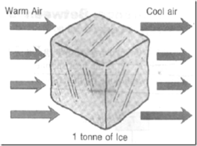
The practical of refrigeration is expressed in terms of ‘tonne of refrigeration’ (briefly written as TR). A tonne of refrigeration is defined as the amount of refrigeration effect produced by the uniform melting of one tonne (l000 kg) of ice from and, at 0°C in 24 hours.
Since the latent heat of ice is 335 kJ/kg, therefore one tonne of refrigeration,
1 TR = 1000 x 335 kJ in 24 hour
= (1000 x 335) / (24 x 60)
= 232.6 kJ/ min
In actual practice, one tonne of refrigeration is taken as equivalent to 210 kJ/ min or 3.5 kW (i.e. 3.5 kJ/ s). One tonne (1000 kg) of ice requires 335 kJ/ kg to melt. When this is accomplished in 24 hours, it is known as a heat transfer rate of 1 tonne of refrigeration (1TR).
Vapour compression system:
Vapour-compression refrigeration, in which the refrigerant undergoes phase changes, is one of the many refrigeration cycles and is the most widely used method for air-conditioning of buildings and automobiles. It is also used in domestic and commercial refrigerators, large-scale warehouses for chilled or frozen storage of foods and meats, refrigerated trucks and railroad cars, and a host of other commercial and industrial services. Oil refineries, petrochemical and chemical processing plants, and natural gas processing plants are among the many types of industrial plants that often utilize large vapour-compression refrigeration systems.
Working Of Vapour Compression Refrigeration System:
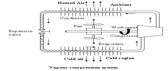
As shown in the figure the basic system consists of an evaporator, compressor, condenser and an expansion valve.
The refrigeration effect is obtained in the cold region as heat is extracted by the vaporization of refrigerant in the evaporator. The refrigerant vapour from the evaporator is compressed in the compressor to a high pressure at which its saturation temperature is greater than the ambient or any other heat sink. Hence when the high pressure, high-temperature refrigerant flows through the condenser, condensation of the vapour into liquid takes place by heat rejection to the heat sink. To complete the cycle, the high-pressure liquid is made to flow through an expansion valve. In the expansion valve the pressure and temperature of the refrigerant decrease. This low pressure and low-temperature refrigerant vapour evaporates in the evaporator taking heat from the cold region. It should be observed that the system operates on a closed cycle. The system requires input in the form of mechanical work. It extracts heat from a cold space and rejects heat to a high-temperature heat sink.
Vapour Compression Cycle -Working Diagram
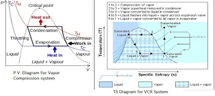 PV And TS Diagram for Vapour Compression System
Most of the modern refrigerators work on this cycle, in its simplest form, there are four fundamental operations required to complete one cycle.
(a) Compression
(b) Condensation
(c) Expansion
(d) Vaporization
a) Compression
The low-pressure Vapour in the dry state is drawn from the evaporator during the suction stroke of the compressor. During compression Stroke, the pressure and temperature increase until vapour temperature is greater than the temperature of condenser cooling medium (air or water)
At point 1 in the diagram, the circulating refrigerant enters the compressor as a saturated vapour. From point 1 to point 2, the vapour is isentropically compressed (i.e., compressed at constant entropy) and exits the compressor as a superheated vapour.
b) Condensation
When the high-pressure refrigerant vapour enters the condenser heat flows from the condenser to the cooling medium thus allowing the vaporized refrigerant to return to the liquid state.
From point 2 to point 3, the vapour travels through part of the condenser which removes the superheat by cooling the vapour. Between point 3 and point 4, the vapour travels through the remainder of the condenser and is condensed into a saturated liquid. The condensation process occurs at essentially constant pressure.
c) Expansion
After condenser the liquid refrigerant is stored in the liquid receiver until needed. From the receiver it passes through an expansion valve where the pressure is reduced sufficiently to allow the vaporization of liquid at a low temperature of about -10°C.
Between points 4 and 5, the saturated liquid refrigerant passes through the expansion valve and undergoes an abrupt decrease of pressure. That process results in the adiabatic flash evaporation and auto-refrigeration of a portion of the liquid (typically, less than half of the liquid flashes).
d) Vaporization
The low-pressure refrigerant vapour after expansion in the expansion valve enters the evaporator or refrigerated space where a considerable amount of heat IS absorbed by it and refrigeration is furnished.
Between points 5 and 1, the cold and partially vaporized refrigerant travels through the coil or tubes in the evaporator where it is vaporized by the warm air (from the space being refrigerated) that a fan circulates across the coil or tubes in the evaporator. The resulting refrigerant vapour returns to the compressor inlet at point 1 to complete the thermodynamic cycle.
The efficiency of a refrigerator or heat pump is given by a parameter called the coefficient of performance (COP).
The equation is:
C.O.P=Q/W
Where
- Q is the useful heat supplied or removed by the considered system.
- W is the work required by the considered system.
The Detailed COP of a refrigerator is given by the following equation:
COPR = (Desired Output)/(Required Input) = (Cooling Effect)/(Work Input) = QL/Wnet,in
The COP of a heat pump (sometimes referred to as coefficient of amplification COA), given by the following equation, where QH = QL + Wnet,in:
COPHP = (Desired Output)/(Required Input) = (Heating Effect)/(Work Input) = QH/Wnet,in = 1 + (QL/Wnet,in)
Both the COP of a refrigerator and a heat pump can be greater than one. Combining these two equations results in:
COPHP = COPR + 1 for fixed values of QH and QL
This implies that COPHP will be greater than one because COPR will be a positive quantity. In a worst-case scenario, the heat pump will supply as much energy as it consumes, making it act as a resistance heater. However, in reality, as in home heating, some of QH is lost to the outside air through piping, insulation, etc., thus making the COPHP drop below unity when the outside air temperature is too low. Therefore, the system used to heat houses uses fuel.[2]
For Carnot refrigerators and heat pumps, COP can be expressed in terms of temperatures:
COPR,Carnot = TL/(TH-TL) = 1/((TH/TL) - 1)
COPHP,Carnot = TH/(TH-TL) = 1/(1 - (TL/TH))
An air conditioner (AC) in a room or a car works by collecting hot air from a given space, processing it within itself with the help of a refrigerant and a bunch of coils and then releasing cool air into the same space where the hot air had originally been collected. This is essentially how air conditioners work.
Window air conditioner:
Window air conditioner is sometimes referred to as room air conditioner as well. It is the simplest form of an air conditioning system and is mounted on windows or walls. It is a single unit that is assembled in a casing where all the components are located.
This refrigeration unit has a double shaft fan motor with fans mounted on both sides of the motor. One at the evaporator side and the other at the condenser side.The evaporator side is located facing the room for cooling of the space and the condenser side outdoor for heat rejection. There is an insulated partition separating these two sides within the same casing.
Front Panel The front panel is the one that is seen by the user from inside the room where it is installed and has a user interfaced control be it electronically or mechanically. Older unit usually are of mechanical control type with rotary knobs to control the temperature and fan speed of the air conditioner.
The newer units come with electronic control system where the functions are controlled using remote control and touch panel with digital display.
The front panel has adjustable horizontal and vertical (some models) louvers where the direction of air flow are adjustable to suit the comfort of the users. The fresh intake of air called VENT (ventilation) is provided at the panel in the event that user would like to have a certain amount of fresh air from the outside.
The mechanical type is usually lower in price compared to the electronic type. If you just want to cool the room and are not too particular about aesthetic or additional functions, the mechanical type will do the work.
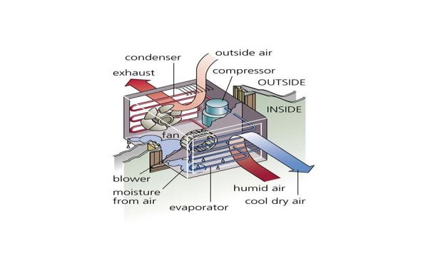
Indoor Side Components
The indoor parts of a window air conditioner include:
- Cooling Coil with an air filter mounted on it. The cooling coil is where the heat exchange happens between the refrigerant in the system and the air in the room.
- Fan Blower is a centrifugal evaporator blower to discharge the cool air to the room.
- Capillary Tube is used as an expansion device. It can be noisy during operation if installed too near the evaporator.
- Operation Panel is used to control the temperature and speed of the blower fan. A thermostat is used to sense the return air temperature and another one to monitor the temperature of the coil. Type of control can be mechanical or electronic type.
- Filter Drier is used to remove the moisture from the refrigerant.
- Drain Pan is used to contain the water that condensate from the cooling coil and is discharged out to the outdoor by gravity.
The outdoor side parts include:
- Compressor is used to compress the refrigerant.
- Condenser Coil is used to reject heat from the refrigeration to the outside air.
- Propeller Fan is used in air-cooled condenser to help move the air molecules over the surface of the condensing coil.
- Fan Motor is located here. It has a double shaft where the indoor blower and outdoor propeller fan are connected together.
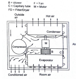
The low pressure and low temperature refrigerant vapour from evaporator is sucked by compressor. The compressor compresses the vapour to high pressure and high temperature and discharges to the condenser. On the condenser the refrigerant vapour condenses by dissipating heat to the cooling medium (air) the liquid refrigerant coming out of condenser passes through filter, dryer into capillary tube where it is again throated back to the evaporated pressure. The low pressure low temp liquid refrigerant then flows to evaporator which it boil off by extracting heat from air to be circuited to the conditioned space.
Split air conditioner
We know that the air conditioner mainly is of two type windows and split. The split name given to split system air conditioners for the very simple reason that they have two components.
There is a cabinet made of metal placed outside while the other part known as the air handler, containing the evaporator coil, is inside. The outdoor unit contains the condenser as well as the compressor, and both these parts are connected to each other using a pipe or a duct. In case of central air conditioning, there are a number of ducts used to connect different rooms, with the bigger unit placed outdoors. Almost all the central air conditioning units are split as they are more energy-efficient.
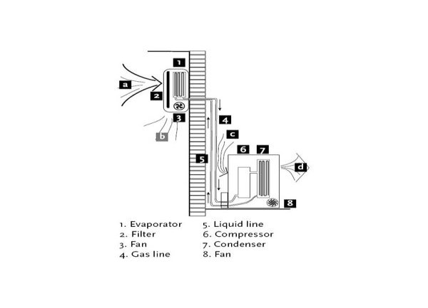
Parts of split air conditioner:
Mainly split ac divided into 2 parts indoor units and outdoor units
Wall Mounted Indoor Unit
It is the indoor unit that produces the cooling effect inside the room. The indoor unit of the split air conditioner is a box type housing in which all the important parts of the air conditioner are enclosed. The most common type of the indoor unit is the wall mounted type though other types like ceiling mounted and floor mounted are also used.
1) Evaporator Coil or the Cooling Coil:
The cooling coil is a copper coil made of number turns of the copper tubing with one or more rows depending on the capacity of the air conditioning system. The cooling coil is covered with the aluminium fins so that the maximum amount of heat can be transferred from the coil to the air inside the room.
The refrigerant from the tubing at very low temperature and very low pressure enters the cooling coil. The blower absorbs the hot room air or the atmospheric air and in doing so the air passes over the cooling coil which leads to the cooling of the air. This air is then blown to the room where the cooling effect has to be produced. The air, after producing the cooling effect is again sucked by the blower and the process of cooling the room continues.
After absorbing the heat from the room air, the temperature of the refrigerant inside the cooling coil becomes high and it flows back through the return copper tubing to the compressor inside the outdoor unit. The refrigerant tubing supplying the refrigerant from the outdoor unit to the indoor unit and that supplying the refrigerant from indoor unit to the outdoor unit are both covered with the insulation tape.
2) Air Filter:
The air filter is very important part of the indoor unit. It removes all the dirt particles from the room air and helps supplying clean air to the room. The air filter in the wall mounted type of the indoor unit is placed just before the cooling coil. When the blower sucks the hot room air, it is first passed through the air filter and then though the cooling coil. Thus the clean air at low temperature is supplied into the room by the blower.
3) Cooling Fan or Blower:
Inside the indoor unit there is also a long blower that sucks the room air or the atmospheric air. It is an induced type of blower and while is sucks the room air it is passed over the cooling coil and the filter due to which the temperature of the air reduces and all the dirt from it is removed. The blower sucks the hot and unclean air from the room and supplies cool and clean air back. The shaft of the blower rotates inside the bushes and it is connected to a small multiple speed motor, thus the speed of the blower can be changed. When the fan speed is changed with the remote it is the speed of the blower that changes.
4) Drain Pipe:
Due to the low temperature refrigerant inside the cooling coil, its temperature is very low, usually much below the dew point temperature of the room air. When the room air is passed over the cooling due the suction force of the blower, the temperature of the air becomes very low and reaches levels below its dew point temperature. Due to this the water vapor present in the air gets condensed and dew or water drops are formed on the surface of the cooling coil. These water drops fall off the cooling coil and are collected in a small space inside the indoor unit. To remove the water from this space the drain pipe is connected from this space extending to the some external place outside the room where water can be disposed of. Thus the drain pipe helps removing dew water collected inside the indoor unit. To remove the water efficiently the indoor unit has to be a tilted by a very small angle of about 2 to 3 degrees so that the water can be collected in the space easily and drained out. If this angle is in opposite direction, all the water will get drained inside the room. Also, if the tilt angle is too high, the indoor unit will shabby inside the room.
5) Louvers or Fins:
The cool air supplied by the blower is passed into the room through louvers. The louvers help changing the angle or direction in which the air needs to be supplied into the room as per the requirements. With louvers one easily change the direction in which the maximum amount of the cooled air has to be passed.
There are two types of louvers: horizontal and vertical. The horizontal louvers are connected to a small motor and there position can set by the remote control. Once can set a fixed position for the horizontal louvers so that chilled air is passed in a particular direction only or one can keep it in rotation mode so that the fresh air is supplied throughout the room. The vertical louvers are operated manually and one can easily change their position as per the requirements. The horizontal louvers control flow of air in upper and downward directions of the room, while vertical louvers control movement of air in left and right directions.
Outdoor Unit
As mentioned previously the outdoor unit is installed outside the room to be air conditioned in the open space. In outdoor unit lots of heat is generated inside the compressor and the condenser, hence there should be sufficient flow of the air around it. The outdoor unit is usually installed at the height above the height of the indoor unit inside the room though in many cases the outdoor is also installed at level below the indoor unit.
The outdoor unit contains the important parts of the split AC like compressor, condenser, expansion valve etc. Let us see these parts in more details:
1) Compressor:
The compressor is most important part of the any air conditioner. It compresses the refrigerant and increases its pressure before sending it to the condenser. The size of the compressor varies depending on the desired air conditioning load. In most of the domestic split air conditioners hermetically sealed type of compressor is used. In such compressors the motor used for driving the shaft is located inside the sealed unit and it is not visible externally. External power has to be supplied to the compressor, which is utilized for compressing the refrigerant and during this process lots of heat is generated in the compressor, which has to be removed by some means.
2) Condenser:
The condenser used in the outdoor unit of split air conditioners is the coiled copper tubing with one or more rows depending on the size of the air conditioning unit and the compressor. Greater the tonnage of the air conditioner and the compressor more are the coil turns and rows. The high temperature and high pressure refrigerant from the compressor comes in the condenser where it has to give up the heat. The tubing is made up of copper since it rate of conduction of heat is high. The condenser is also covered with the aluminium fins so that the heat from the refrigerant can be removed at faster rate.
3) Condenser Coil
Condenser Cooling Fan:
The heat generated within the compressor has to be thrown out else the compressor will get too hot in the long run and its motor coils will burn leading to complete breakdown of the compressor and the whole air conditioner. Further, the refrigerant within the condenser coil has to be cooled so that after expansion its temperature becomes low enough to produce the cooling effect. The condenser cooling fan is an ordinary fan with three or four blades and is driven by a motor. The cooling fan is located in front of the compressor and the condenser coil. As the blades of the fan rotate it absorbs the surrounding air from the open space and blows it over the compressor and the condenser with the aluminium fins thus cooling them. The hot air is thrown back to the open space and the circulation of air continues unhindered.
4) Expansion Valve:
The expansion valve is usually copper capillary tubing with several rounds of coils. In the split air conditioners of bigger capacities thermostatic expansion valve is used which is operated electronically automatically. The high pressure and medium temperature refrigerant leaves the condenser and enters the expansion valve, where its temperature and pressure drops suddenly.
Working of split AC:
The outdoor unit of a split system air conditioner contains the refrigerant. The refrigerant is a gas pressurised into the compressor. There are many ducts or tubes in a ducted air conditioning unit through which the gas passes. This later condenses into liquid form.
This liquid then passes through the expansion joint and gets converted into a gaseous state. This releases a large amount of heat in the process.
The resultant gas is used for cooling the air at a very low temperature and hence called the refrigerant. This is a cyclic process which continues as the gas flows back into the compressor. The air of your room passes through the cavity containing evaporator coils. These coils contain gas at extremely low temperatures, thus cooling the air.
The thermostat present inside air conditioning units controls the temperature and the air continues to stay in the evaporator area till the desired temperature is obtained. It is then blown into the room.
Thus, your split system air conditioner sucks in the warm air and lowers its temperature before blowing it back into the room. The moisture inside the room condenses in the process, which is then removed through a drain pipe present in the outdoor unit.