Unit 4
Introduction to Manufacturing Systems
Welding
There are numerous types of welding processes, including:
- Arc
- Electron Beam
- Friction
- Laser
- Resistance
Welding has been used to join most metals known to humankind, but the process is extensively used for common manufacturing materials, such as aluminium, steel and titanium. Welded components are in use all around us in everyday life, such as in aeroplanes, bridges, buildings, cars and ships.
Arc welding
It is a fusion welding process in which the melting and joining of metals is done by the heat energy generated by the arc between the work and electrode.
An electric arc is generated when the electrode contacts the work and then quickly separated to maintain the gap. A temperature of 5500°C is generated by this arc.
This temperature is sufficient to melt most of the metals. The molten metal, consisting of base metal and filler, solidifies in the weld region. In order to have seam weld, the power source moves along the weld line.
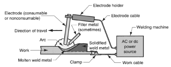
Electrodes
• Two types of electrodes are used: consumable and non-consumable
• Consumable electrodes: Present in rod or wire form with 200 to 450 mm length and less than 10 mm diameter. This is the source of filler rod in arc welding. The electrode is consumed by the arc during the welding process and added to the weld joint as filler metal. The consumable electrodes will be changed periodically as it is consumed for each welding trials. This becomes a disadvantage for welder and reduces the production rate.
• Non-Consumable electrodes: The electrodes are not consumed during arc welding. Though this is the case, some depletion occurs because of vaporization. Filler metal must be supplied by means of a separate wire that is fed into the weld pool.
Advantages of Welding Include:
- Produces stronger joints than brazing or soldering
- Produces welded joints that are better suited for high-temperature applications
- Being able to join thin and thick sections of metal (depending on process type)
- Welding provides a permanent joint.
- Welded joint can be stronger than the parent materials if a proper filler metal is used that has strength properties better than that of parent base material and if defect less welding is done.
- • It is the economical way to join components in terms of material usage and fabrication costs. Other methods of assembly require, for example, drilling of holes and usage of rivets or bolts which will produce a heavier structure.
Disadvantages of Welding Include:
- Producing greater thermal distortion and residual stresses in the joint compared to soldering and brazing
- Requiring a post-processing heat treatment to relieve joint residual stress (depending on application and process)
- Only being able to join similar base materials (for most processes, but not all)
- Labour costs are more since manual welding is done mostly.
- Dangerous to use because of presence of high heat and pressure.
- Disassembly is not possible as welding produces strong joints.
- Some of the welding defects cannot be identified which will reduce the strength.
Soldering
Solders are melted using heat from a temperature-controlled soldering iron. The solder melts at a temperature below 450°C. A flux is used in soldering to clean the metal surfaces, allowing easier flow of the liquid filler metal over the base material.
Base materials suitable for joining by soldering include brass, copper, iron, gold and silver. Filler metals used in soldering were once lead based, however, owing to regulations, lead-based solders are increasingly replaced with non-lead versions, which may consist of antimony, bismuth, and copper, indium, tin or silver.
Soldering is widely used in the electronics industry for making electrical connections, such joining copper to printed circuit boards (PCB). Plumbers also use the process to join copper pipes. One high-value application of soldering is for the assembly of jewellery.
Advantages of Soldering Include:
- Having a lower power input and processing temperature compared to welding and brazing
- Being able to join dissimilar base materials
- Being able to join thin walled parts
- Having minimal thermal distortion and residual stresses in the joints
- Not needing a post-processing heat treatment
Disadvantages of Soldering Include:
- Producing lower strength of joints compared to welding and brazing, making them undesirable for load-bearing applications
- Not being able to join large sections
- Producing joints that are unsuitable for high-temperature applications
- Fluxes may contain toxic components
Brazing
Brazing is considered as a high-temperature version of soldering. There are several brazing variants, including torch brazing, vacuum brazing, furnace brazing and induction brazing. Regardless of the type, the braze filler metal melts at a temperature above 450°C, but always below that of the base materials to be joined. The filler metal, while heated slightly above melting point, is protected by a suitable atmosphere, which is often supplied by a flux. The flux, as with soldering, also helps to clean the metal surfaces.
Base materials suitable for brazing include aluminium, copper, gold, nickel, silver and steel. Primary filler metals used in brazing include aluminium, cobalt, copper, gold, nickel or silver. These primary filler metals are often alloyed with other elements to obtain desirable properties and performance.
Brazing is a commercially accepted process used in a wide range of industries due to its flexibility and the high integrity to which joints may be produced. This makes it reliable in critical and non-critical applications, and it is one of the most widely used joining methods.
It is a joining process in which a filler metal is melted and distributed by capillary action between the faying (contact) surfaces of the metal parts being joined. Base material does not melt in brazing; only the filler melts.
In brazing, the filler metal has a melting temperature (liquidus) above 450°C, but below the melting point (solidus) of base metals to be joined.
Advantages of Brazing Include:
- Having a lower power input and processing temperature than welding
- Producing joints with minimal thermal distortion and residual stresses when compared to welding
- Not needing a post-processing heat treatment
- Being able to join dissimilar base materials
- Producing stronger joints than soldering
Disadvantages of Brazing Include:
- Producing lower strength joints compared to welding
- Producing joints that are not as well suited to high-temperature applications as welds
- Fluxes may contain toxic components
Casting manufacturing is a process in which liquefied material, such as molten metal, is poured into the cavity of a specially designed mold and allowed to harden. After solidification, the workpiece is removed from the mold to undergo various finishing treatments or for use as a final product. Casting methods are typically used to create intricate solid and hollow shapes, and cast products are found in a wide range of applications, including automotive components, aerospace parts, etc.
Benefits of the Casting Process
Casting is but one method of metal shaping, as there are many other options, including welding, forging, stamping, and extrusion and machining. Before settling on casting, you should first understand the benefits that the process provides over these other techniques. The casting process:
- Ability to create complex geometries: Liquid metal facilitates construction of intricate designs, in either simple or complex geometries.
- Fast production cycles: Once the casting tools are in order, very little maintenance and downtime is necessary. This makes casting an option for mass production applications.
- Workability of hard metals: Casting is often one of the only viable manufacturing processes for hard metals that are not malleable enough for solid state shaping.
- Reduced assembly: Oftentimes, casting can create items in a single, complete component, eliminating the need to assemble multiple pieces.
- Minimal sizing restraints: Casting can create extremely small to extremely large parts, even up to 200 tons.
- Versatile surface textures: Casting moulds can be designed to deliver smooth, semi-smooth or rough surface textures.
Types of Casting Processes
There are several different casting methods, each of which requires slight variations in the process. The categorization of the different types of processes is based on the material used to make the moulds. Casting options include:
- Sand casting
- Plaster casting
- Shell moulding
- Wax casting
- Die casting
- Centrifugal casting
Although casting is one of the oldest known manufacturing techniques, modern advances in casting technology have led to a broad array of specialized casting methods. Hot forming processes, such as die-casting, investment casting, plaster casting, and sand casting, each provide their own unique manufacturing benefits. Comparing both the advantages and disadvantages of the common types of casting processes can help in selecting the method best suited for a given production run.
Sand Casting
Sand casting typically relies on silica-based materials, such as synthetic or naturally-bonded sand. Casting sand generally consists of finely ground, spherical grains that can be tightly packed together into a smooth molding surface. The casting is designed to reduce the potential for tearing, cracking, or other flaws by allowing a moderate degree of flexibility and shrinkage during the cooling phase of the process. The sand can also be strengthened with the addition of clay, which helps the particles bond more closely. Automotive products such as engine blocks are manufactured through sand casting.
Sand casting involves several steps, including patternmaking, molding, melting and pouring, and cleaning. The pattern is the form around which the sand is packed, usually in two parts, the cope and the drag. After the sand is compacted enough to replicate the pattern, the cope is removed and the pattern extracted. Then, any additional inserts called core boxes are installed and the cope is replaced. After the metal has been poured and solidified, the casting is removed, trimmed of the risers and gates that were used in the pouring process, and cleaned of any adhered sand and scale.
Sand casting's main advantages as a casting process include:
- Relatively inexpensive production costs, especially in low-volume runs.
- The ability to fabricate large components.
- A capacity for casting both ferrous and non-ferrous materials.
- A low cost for post-casting tooling.
Despite its benefits, sand casting yields a lower degree of accuracy than do alternate methods and it can be difficult to sand cast components with a predetermined size and weight specifications. Furthermore, this process has a tendency to yield products with a comparatively rough surface finish.
Investment Casting
Investment, or lost-wax, casting uses a disposable wax pattern for each cast part. The wax is injected directly into a mold, removed, then coated with refractory material and a binding agent, usually in several stages to build up a thick shell. Multiple patterns are assembled onto common sprues. Once the shells have hardened the patterns are inverted and heated in ovens to remove the wax. Molten metal is then poured into the remaining shells where it hardens into the shape of the wax patterns. The refractory shell is broken away to reveal the completed casting. Investment casting is often used to manufacture parts for the automotive, power generation, and aerospace industries, such as turbine blades. Some of the central advantages and disadvantages of investment casting include:
- A high degree of accuracy and precise dimensional results.
- The ability to create thin-walled parts with complex geometries.
- The capacity for casting both ferrous and non-ferrous materials.
- Relatively high-quality surface finish and detail in final components.
Although it is highly precise, investment casting is usually more expensive than other comparable casting techniques and is typically only cost-efficient when sand or plaster castings cannot be used. However, the expense can sometimes be compensated for with reduced machining and tooling costs due to investment castings’ quality surface results.
Plaster Casting
Plaster casting is similar to the sand casting process, using a mixture of gypsum, strengthening compound, and water in place of the sand. The plaster pattern is typically coated with an anti-adhesive compound to prevent it from becoming stuck against the mold, and the plaster is capable of filling in any gaps around the mold. Once the plaster material has been used to cast the part, it usually cracks or forms defects, requiring it to be replaced with fresh material. The advantages offered by plaster casting include:
- A very smooth surface finish.
- The ability to cast complex shapes with thin walls.
- The capacity for forming large parts with less expense than other processes, such as investment casting.
- A higher degree of dimensional accuracy than that of sand casting.
This process tends to be more expensive than most sand casting operations and may require frequent replacements of the plaster molding material. It is usually more effective and cost-efficient when the quality of the surface finish is an important requirement. Its application is generally limited to casting aluminium and copper-based alloys.
Die Casting (Metal Casting Process)
Die casting is a method of molding materials under high pressure and usually involves non-ferrous metals and alloys, such as zinc, tin, copper, and aluminium. The reusable mold is coated with a lubricant to help regulate the die’s temperature and to assist with component ejection. Molten metal is then injected into the die under high pressure, which remains continuous until the workpiece solidifies. This pressurized insertion is rapid, preventing any segment of the material from hardening before being cast. After the process is completed, the component is taken out of the die and any scrap material is removed. A few of the major advantages provided by die casting include:
- Close size and shape tolerances.
- High component dimensional consistency and uniform design.
- A reduced need for post-casting machining.
Despite its advantages, die casting as a metal casting process has relatively high tool costs, making it more cost-efficient in high-volume product runs. It can also be difficult to ensure the mechanical properties of a die-cast component, meaning these products usually do not function as structural parts. As the molds are typically two-piece, die casting is limited to products that can be removed from the mold without destroying the mold, as is done in other casting processes.
Centrifugal Casting
Centrifugal casting is used to produce long, cylindrical parts such as cast iron pipe by relying on the g-forces developed in a spinning mold. Molten metal introduced into the mold is flung against the interior surface of the mold, producing a casting that can be free of voids. Originally invented as the de Levied process using water-cooled molds, the method is applied to symmetrical parts such as soil pipe and large gun barrels and has the advantage of producing parts using a minimal number of risers. For asymmetric parts that cannot be spun around their own axes, a variant of centrifugal casting, called pressure casting, arranges several parts around a common sprue and spins the molds around this axis. A similar idea is applied to the casting of very large gear rings, etc. Depending on the material being cast, metal or sand molds may be used.
Permanent Mold Casting
Permanent mold casting shares similarities with die casting and centrifugal casting, notably the use of reusable molds. These can be made of steel, graphite, etc. and are generally used to cast materials such as lead, zinc, aluminium and magnesium alloys, certain bronzes, and cast iron. It is a low-pressure process with pouring usually done by hand using multiple molds on a turntable. As the molds rotate through the various stations they are successively coated, closed, filled, opened, and emptied. One such method is known as slush casting, where the mold is filled but emptied before the metal fully hardens. Molten metal is dumped from the casting to produce a hollow, cast shell. A similar idea is used in the molding of hollow chocolate products such as Easter bunnies. The use of metal molds induces faster heat transfer through the mold, allowing the shell to harden while the core remains liquid.
Steps involved in casting processes
There are many steps and things to consider when manufacturing products through the technique of casting and the casting process. This guide explains the process involved with casting and benefits of using this popular forming method.
In casting, a molten metal or other material fills a mold, then cools and hardens into a desired shape. However, a manufacturer must plan out post-cast steps to ensure effective results. Proper care should be taken at each step to deliver a final product that maintains proper quality and integrity.
Basic Steps in Casting Process
While each casting method creates unique challenges and process enhancements, all techniques retain the same basic steps. These steps are:
- Patternmaking
- Core making
- Molding
- Melting and pouring
- Finishing
Patternmaking
To create a casting mould, a manufacturer must first design a physical model. The process of fabricating this model is called patternmaking. Using computer-assisted design (CAD) systems, the manufacturer designs dimensions and geometry of a mould, and then packs an aggregate material, such as sand, concrete or plastic, around the pattern. Once the pattern is removed, the mould cavity in the sand can be filled.
A pattern is a replica of the exterior of the casting. Patterns are typically made of wood, metal, plastic, or plaster. Patternmaking is incredibly important for industrial part-making, where precise calculations are needed to make pieces fit and work together.
Core making – If a casting is hollow, an additional piece of sand or metal (called a core) shapes the internal form to make it hollow. Cores are typically strong yet collapsible so they can be easily removed from the finished casting.
Many part designs require the inclusion of cores in the casting mould. Cores are solid materials placed inside the mould cavity to create interior surfaces of a casting. For example, a metal pipefitting will require a cylindrical core inside the mould cavity to create the hollow construction of the components interior
Moulding – At this point, the manufacturer can create the casting mold. A material such as sand, plaster or wax is used in expendable mold casting, whereas metal and other durable materials are used in non-expendable mold casting techniques. The material fills the casting mold model and is allowed to harden, at which point the manufacturer removes it from the cavity and the casting of the component can now begin.
To visualize the metal casting process so far, imagine yourself walking on the beach toward the ocean. Look at a footprint you leave behind in the wet sand. Your foot would be the core, and the impression left in the sand is a mould of your foot. Molding is a multistep process that will form a cast around the pattern using moulding sand. In casting, a mould is contained in a frame called a flask. Green sand, or moulding sand, is packed into the flask around the pattern. This is known as metal sand casting. Once the sand is packed tight, the pattern can be removed and the cast will remain. Alternatively, a two-piece, non-destructible metal mould can be created so that the mould can be used repeatedly to cast identical parts for industrial applications.
Melting and Pouring
Metal must be properly melted prior to being placed in the mold. Typically, this is done by using what is known as a crucible. Crucibles are containers made of porcelain or another melt-resistance substance in which a manufacturer can heat a metal beyond its melting point. Once properly melted, the molten metal is poured into the casting mold to cool and harden.
Finishing
Because metal can sometimes fill in cracks in a casting mold or sprues, the pouring channel for the mold, manufacturers must often finish the metal following casting. This can be accomplished through a variety of finishing techniques, including sanding, grinding and buffing. Once proper appearance and surface texture has been achieved, further post-treatment processes such as painting or electroplating may be necessary for some applications.
Things to Consider When Casting
There are numerous factors that need to be considered to ensure proper size, shape and integrity of the final component. Some of these factors include:
- Type of material: each metal and casting material retains specific characteristics (hardness, melting point, density, etc.) that will affect the casting process.
- Cooling rate: This factor depends largely on the type of material from which you craft the mold. Proper cooling is necessary to minimize gas porosity and other negative properties that can result from a fast cooling rate.
- Shrinkage: As castings cool, they shrink. To ensure proper component size and integrity, you can utilize risers to feed additional molten metal into the cavity. An oversized mold may also be useful in some applications.
Casting applications
Castings can range in size from a few grams (for example, watch case) to several tones (marine diesel engines), shape complexity from simple (manhole cover) to intricate (6-cylinder engine block) and order size one-off (paper mill crusher) to mass production (automobile pistons).
The desired dimensional accuracy and surface finish can be achieved by the choice of process and its control. Castings enable many pieces to be combined into a single part, eliminating assembly and inventory and reducing costs by 50% or more compared to machined parts. Unlike plastics, castings can be efficiently and completely recycled.
Today, castings are used in virtually all walks of life. The following is a partial list of applications, with transport sector and heavy equipment taking up over 50% of castings produced:
- Transport: automobile, aerospace, railways and shipping
- Heavy equipment: construction, farming and mining
- Machine tools: machining, casting, plastics moulding, forging, extrusion and forming
- Plant machinery: chemical, petroleum, paper, sugar, textile, steel and thermal plants
- Defense: vehicles, artillery, munitions, storage and supporting equipment
- Electrical machines: motors, generators, pumps and compressors
- Municipal castings: pipes, joints, valves and fittings
- Household: appliances, kitchen and gardening equipment, furniture and fittings
- Art objects: sculptures, idols, furniture, lamp stands and decorative items.
Virtually any metal or alloy that can be melted can be cast. The most common ferrous metals include grey iron, ductile iron, malleable iron and steel. Alloys of iron and steel are used for high performance applications, such as temperature, wear and corrosion resistance. Table 1 lists the major metals in use today (by weight) along with their main characteristics and typical applications.
The most used metals, characteristics and applications
Metal | Use | Characteristics | Applications |
Grey | 54% | Heat resistance, damping, low cost, | Automobile cylinder block, clutch plate, |
Ductile | 20% | Strength, wear and shock resistance, | Crank shafts, cam shafts, differential |
Steel | 9% | Strength, machinability, weldability | Machine parts, gears, valves |
Hot and Cold working Processes:
The metal working processes are derived into hot working and cold working processes. The division is on the basis of the amount of heating applied to the metal before applying the mechanical force. Those processes working above the re-crystallization temperature are hot working processes whereas the below or termed as cold working processes.
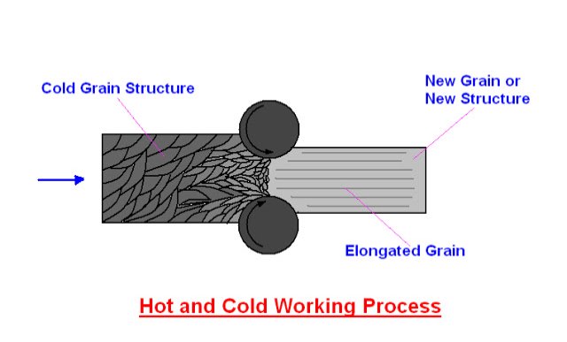
Under the action of heat and force when the atom reach a certain high energy level the new crystal start forming , which is termed as re- crystallization. Re-crystallization destroys the old grain structure deform by the mechanical working and entirely new crystal which are strain free and form.
Re-crystallization temperature is defined as the approximate minimum temperature at which complete re-crystallization of a cold work metal occurs with in a specified time.
Hot working processes.
Hot working of metals takes place above re-crystallization by hot working processes the metal are given desired shape by subjecting then two forces which cause then to undergo plastic deformation at the temperature above the re-crystallization range.
Different hot working processes are as follows:
1: Forging
- Hammer or smith forging
- Drop forging
- Upset forging
- Press forging
- Roll forging
- Swaging
2: pipe welding
- Butt welding of heated strips
- Butt welding of electrical resistance
- Lap welding
- Hammer welding
3: Rolling
4: Piercing
5: Spinning
6: Extruding
7: Drawing or Cupping
Cold working processes:
Below the re crystallization temperature if the mechanical work is done on the metals , there will no grain growth but it must be grain this integration elongation the process is known is cold working processes. In cold working process greater pressure is required than that required in hot working. As the metal is in a more rigid state. It is not permanently deform until stress exceeds the elastic limit. Most of the cold processes are performed at room temperature , the different cold working processes are
1: Drawing
- Wire drawing
- Tube drawing
- Blanking
- Spinning
2: Squeezing
- Coining
- Sizing
- Riveting
3: Bending
- Angle bending
- Plate bending
- Roll forming
4: Shearing
- Punching
- Blanking
- Trimming
- Perforating
- Notching
- Launcing
- Slitting
5:Extruding
Difference between Hot rolling and cold rolling processes |
Hot rolling | Cold rolling |
1: Metal is fed to the rolls after being heated above the recrystallization temperature. | 1: Metal is fed to the rolls when it is below the recrystallization temperature. |
2: In general rolled metal does not shows work hardening effect. | 2: The metal shows the working hardening effect after being cold rolled. |
3: Co-efficient of friction between two rolls and the stock is higher, it may even caused shearing of the metal in contact with rolls. | 3: Co-efficient of friction between two rolls and the stock is comparatively lower. |
4: Experiment measurement are difficult to make. | 4: Experiment measurement can be carried out easily in cold rolling. |
5: Heavy reduction in area of the work piece can be obtained. | 5: Heavy reduction is not possible. |
6: Mechanical properties are improved by breaking cast structure are refining grain sizes below holes and others, similar deformation in ingot (get welded) and or removed the strength and the toughness of the job should increases. | 6: Hotness increased excessive cold working greatness crackers ductility of metal reduction. Cold rolling increased the tensile strength and yield strength of the steel. |
7:Rolls radius is generally larger in siz. | 7: Rolls radius is smaller. |
8: Very thin sections are not obtained. | 8:Thin sections are obtained. |
9: Hot roll surface has(metal oxide) on it , this surface finish is not good. | 9: The cold rolled surface is smooth and oxide free. |
10: Hot rolling is used un ferrous as well as non ferrous metals such as industries for steel ,aluminum, copper , brass, bronze , alloy to change ingot into slabs. | 10: Cold rolling is equally applicable to both plain and alloys steels and non ferrous metals and their alloys. |
11: Hot rolling is the father of the cold rolling. | 11: Cold rolling follows the hot rolling.
|
Rolling:
Rolling is a process where the metal is compressed between two rotating rolls for reducing its cross sectional area. This is one of the most widely use of all the metal working processes. Because of its higher productivity and low cost. Rolling would be able to produce components having cross sectional through out its length. May shape such as itl and channel section are possible , but not very complex shapes.
Rolling is normally a hot working process unless specifically mentions as cold working. The metal is taken into rolls by friction and subsequently compressed to obtain the final shape.
The thickness of the metal that can down into rolls depends on the roughness of the roll surface. Rougher rolls would be able to achieve greater reduction than smoother rolls. The reduction that would be achieved with a given set of roll is designed as the angle of the bite. Cold rolling is done bellow the re-crystallization temperature of the metal hot rolling is done when the metal pieces at uniform working temperature.
Types of Rolling mills
Rolling mills may be classified according to the number and arrangement of the rolls.
(a): Two high rolling mills
(b): Three high rolling mills
(c): Four high rolling mills
(d): Tandem rolling mills
(e): Cluster rolling mills
1: two high rolling mills
Two high rolling mills may further classified as
- Reversing mill
- Non-reversing mill
- A two high rolling mill has two rolls only.
Two high reversing mill:
In two high reversing rolling mills the rolls rotates in one direction and then in the other, so that rolled metal may pass back and forth through the rolls several times. This type is used in pluming and slabbing mills and for roughing work in plate , rail , structural and other mills.
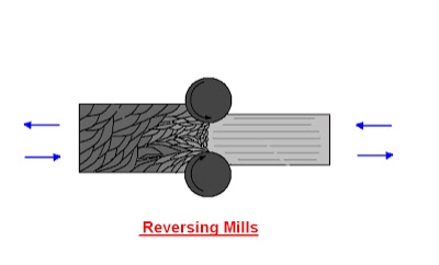
These are more expensive compared to the non-reversing rolling mills. Because of the reversible drive needed.
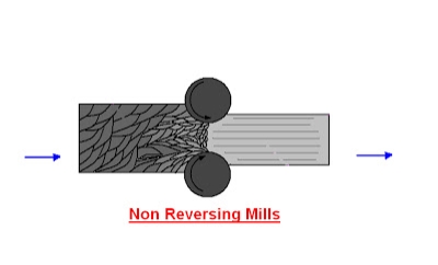
Two high non-reversing mill:
In two high non-reversing mills as two rolls which revolve continuously in same direction therefore smaller and less costly motive power can be used. However every time material is to be carried back over the top of the mill for again passing in through the rolls. Such an arrangement is used in mills through which the bar passes once and in open train plate mill.
2: three high rolling mills:
It consists of a roll stand with three parallel rolls one above the other. Adjacent rolls rotate in opposite direction. So that the material may be passed between the top and the middle roll in one direction and the bottom and middle rolls in opposite one.
In three high rolling mills the work piece is rolled on both the forward and return passes. First of all the work piece passes through the bottom and middle rolls and the returning between the middle and the top rolls.
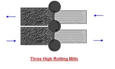
So that thickness is reduced at each pass. Mechanically operated lifted tables are used which move vertically or either side of the stand. So that the work piece fed automatically into the roll gap. Since the rolls run in one direction only a much less powerful motor and transmission system is required. The rolls of a three high rolling mills may be either plain or grooved to produce plate or sections respectively.
3: four high rolling mills:
It has a roll stand with four parallel rolls one above the other. The top and the bottom rolls rotate in opposite direction as do the two middle rolls. The two middle are smaller in size than the top and bottom rolls which are called backup rolls for providing the necessary rigidity to the smaller rolls.
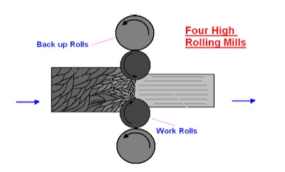
A four high rolling mill is used for the hot rolling of armour and other plates as well as cold rolling of plates, sheets and strips.
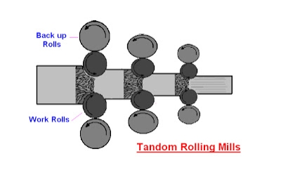
4: Tandem rolling mills:
It is a set of two or three stands of roll set in parallel alignment. So that a continuous pass may be made through each one successively with change the direction of material.
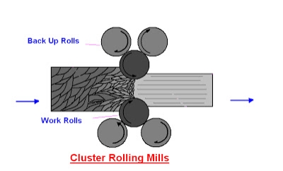
5: Cluster rolling mills:
It is a special type of four high rolling mill in which each of the two working rolls is backup by two or more of the larger backup rolls for rolling hard in materials. It may be necessary to employ work rolls of a very small diameter but of considerable length. In such cases adequate of the working rolls can be obtained by using a cluster mill.
Heat treatingcan be applied to the part before to make the material more machinable, or the components may be machined before the final hardening and heating stages. Heat treating can affect a number of different aspects of the metal including strength, hardness, toughness, machinability, formability, ductility, and elasticity. It can also affect the physical and mechanical properties of metal to change the use of the metal or alter future work on the metal. Here we take a closer look at the different types of heat treating and how these affect the parts during precision machining.
HARDENING
In heat treating to harden a metal, the metal is heated to a temperature where the elements in the metal become a solution. Before doing this, defects in the crystal lattice structure of metal are the primary source of ‘give’ or plasticity. Heat treating addresses those deficiencies by bringing the metal into a reliable solution with fine particles to strengthen the metal. Once the metal is thoroughly heated to the right temperature to produce a solid solution, it is quickly quenched to trap the particles in solution.
In precipitation hardening, impurity particles are added to the metal alloy to increase strength further.
CASE HARDENING
In the process of case hardening, the external layer of metal is hardened while the interior metal remains soft. For metals with a low carbon content such as iron and steel, additional carbon has to be infused into the surface. Case hardening is a process often used as a final step after the piece has already been machined. High heat is used in combination with other elements and chemicals to produce a hardened outer layer. Because hardening can make metals more brittle, case hardening can be useful for applications that require a flexible metal with a durable wear layer.
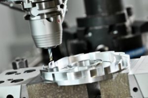
ANNEALING
Annealing is a heat treatment method where a metal such as aluminium, copper, steel, silver, or brass is heated to a specific temperature, held at that temperature for some time to allow transformation to occur, and then air cooled. This process increases the metal’s ductility and decreases hardness to make the metal more workable. Copper, silver, and brass can be cooled quickly or slowly, whereas ferrous metals like steel must always be cooled gradually to allow annealing to occur. Annealing may be used before a metal is machined to improve its stability, making harder materials less likely to crack or fracture.
NORMALIZING
Normalizing is an annealing process for steel where it is heated 150-200°F higher than in annealing and held at the critical temperature long enough for the transformation to occur. Steel treated in this way must be air cooled. The heat treating in normalization causes smaller austenitic grains, while air cooling produces more refined ferritic grains. This process improves machinability, ductility, and strength of the steel. Standardization is also useful to remove columnar grains and dendritic segregation that can occur during the casting of a part.
TEMPERING
Tempering is a method of heat treating used to increase the resilience of iron-based alloys like steel. Iron-based metals are very hard, but they are often too brittle to be useful for most purposes. Tempering can be used to change the hardness, ductility, and strength of metal, which usually makes it easier to machine. The metal will be heated to a temperature below the critical point as lower temperatures reduce brittleness while maintaining hardness. For increased plasticity with less hardness and strength, higher temperatures are required.
Another option is to purchase material that has been hardened or to harden the material before machining. While this makes it more difficult to machine, it eliminates the risk for the part sizes changing, unlike a post-machining heat treatment process. It can also eliminate the need for a grinding shop to get the tight finishes or tolerances.
INVERSE SOLUTIONS, INC. IS ONE OF THE ONLY MACHINE SHOPS THAT CAN PURCHASE ALREADY HARDENED MATERIAL.
The heat treatment can be an essential part of the precision machining process to transform metals and ensure your pieces and parts perform as you need them to. Talk to one of our qualified precision engineers about your requirements and how to find the right method of heat treating for your precision engineering project.
Power Transmission Methods and Devices:
Type of belt and belt drives:
The belt or ropes are used to transmit power from one shaft to another by means of pulleys which rotate at the same speed or at different speed.
The amount of power transmission depends upon the following factors:
- Velocity of the belt.
- The tension under which the belt is placed on the pulleys.
- He arc of contact between the belt and the smaller pulley.
- Selection of belt drive.
Selection of belt drive: Following are the various important factors upon which the selection of belt drive depends.
- Speed of the driving and driven shaft
- Speed reduction ratio
- Power to be transmitted
- Centre distance between the shaft
- Positive drive requirements
- Shaft layout
- Speed available
- Service conditions.
TYPE OF BELT DRIVES: The belt drive usually classified into following 3 groups:
1- Light drives- These are used to transmit small powers at belt speeds up to about 10 m/s as in agricultural machines and small machines tools.
2- Medium drives- These are used to transmit medium powers at belt speeds over 10 m/s but up to 22 m/ s as in machine tools.
3- Heavy drives- These are used to transmit large powers at belt speeds above 22 m/s as in compressors and generators.
TYPES OF BELTS: Though there are many types of belts used these days, yet the following important belt drive shown below.
1) Flat belt drive – This belt is mostly used in factories and workshops, where a moderate amount of power is to be transmitted, from one pulley to another when two pulleys are not more than 8 metres apart.
2) V-belts- This belt is mostly used in factories and workshops, where a moderate amount of power is to be transmitted, from one pulley to another when two pulleys are very near to each other.
3) Circular belt or rope- This belt is mostly used in factories and workshops, where a great amount of power is to be transmitted, from one pulley to another when two pulleys are more than 8 metres apart.

FLAT BELT DRIVE: There are different type of flat belt drive which used in factories and workshop, some are given below:
- Open belt drive.
- Cross belt drive.
- Stepped or cone pulley or speed cone drive.
- Fast and loose pulleys.
- Jockey pulley drive or belt drive with idler pulley
- Compound Belt Drive System
- Open Belt Drive:
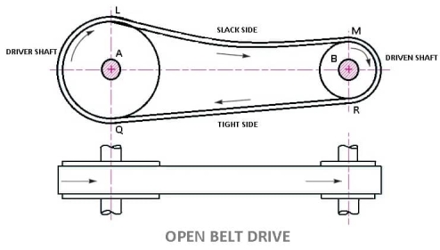
- In these types of belt drive, the belt is employing when the two parallel shafts have to rotate in the same direction.
- When the shafts are far apart, the lower side of the belt should be the tight side and the upper side must be the slack side.
- This is because, when the upper side becomes the slack side, it will sag due to its own weight and thus increase the arc of contact.
LENGTH OF OPEN BELT DRIVE FORMULA:
= π (r1 + r2) + 2x + (r1 – r2)2 /x ……………. (In terms of pulley radii)
= π/2 (d1 + d2) + 2x + (d1 – d2)2/ 4x ……….… (In terms of pulley diameters)
2. Cross Belt Drive
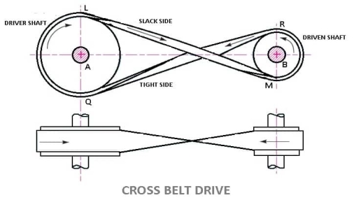
- In this types of belt drives, the belt is employing when two parallel shafts have to rotate in the opposite direction. At the junction where the belts cross, it rubs against itself and wears off.
- To avoid excessive wear, the shafts must be placed at a maximum distance from each other and operated at very low speeds.
LENGTH OF CROSS BELT DRIVE
= π (r1+r2) + 2x + (r1+r2)2 /x …………… (In terms of pulley radii)
= π/2(d1+d2) +2x + (d1 + d2)2/ 4x …………(in terms of pulley diameters)
3. Stepped or Cone Pulley or Speed Cone Drive
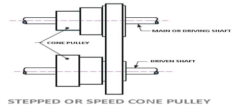
- This types of belt drives are used when the speed of the driven shaft is to be changed very frequently as in the case of machine tools such as lathe, drilling machine, etc.
- A stepped cone pulley is an integral casting having three or number of pulleys of different sizes one adjacent to the other as shown in fig.
- One set of stepped cone pulley is mounted in reverse on the driven shaft. An endless belt will be wrapped around one pair of pulleys.
- By shifting the belt from one pair of pulleys to the other, the speed of the driven shaft can be varied.
- The diameter of the driving and driven pulleys is such that the same belt will operate when shifted on different pairs of pulleys.
4. Fast and Loose Pulley Drive
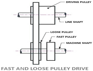
- This types of belt drives are used when the driven or machine shaft is to be started or stopped whenever desired without interfering with the driving shaft.
- A pulley which is keyed to the machine shaft is called a fast pulley and run at the same speed as that of the machine shaft.
- A loose pulley runs freely over the machine shaft and is incapable of transmitting any power.
- When the driven shaft is required to be stopped, the belt is pushed on to the loose pulley by means of a sliding bar having belt forks.
5. Jockey Pulley Drive or belt drive with idler pulleys:
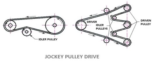
- In an open belt drive arrangement, if the centre distance is small, or if the driven pulleys are very small, then the arc of contact of the belt with the driven pulley will be very small, which reduces the tensions in the belt, or if the required tension of the belt cannot be obtained by other means, an idler pulley, called jockey pulley is placed on the slack side of the belt as shown in fig.
- Which increases the arc of contact and thus the tension which results in increased power transmission
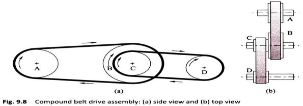
6.Compound Belt Drive System:
In compound belt drive arrangement power is transmitted from one shaft to another through a number of pulleys.
V-BELTS DRIVE-
The V-belts or “V” types of belt drives are widely used in high power transmission. V-belts are trapezoidal in section as shown in the figure. They are moulded as endless loops from rubber reinforced with fibrous material. They run in the v-grooves made in the pulleys.
The wedging action of the belts in the V-grooves enables them to transmit higher torques. The power transmitted by a v-belt drive and be increased by operating with several belts placed side.
This form of drive is used extensively in all classes of machinery transmitting power from 0.5 kW up to 150kW.
Advantages of Belt-drive:
A belt-drive has following advantages:
- It can easily install and easily remove.
- The price of the belt drive is low.
- Simple in construction.
- The maintenance cost is low.
- No additional lubricant is required.
- It can transfer power vertical, horizontal and inclined too.
- Power consumption is low.
Disadvantages of Belt-drive:
- Power loss due to slip and creep.
- Not used for a very short distance.
- Speed is limited to some extent.
- It is quieter.
- Longer life is not possible.
- Chances of breaking are more.
- The operation temperature is limited between -35 to 85 degrees Celsius. If it exceeds temperature then it causes wear.
- Angular velocity ratio is not necessarily constant or equal to the ratio of pulley’s diameter because of slipping.
Applications of Belt-drive: Belt-drives are used in various places like:
- A belt drive is used to transfer power.
- The belt drive is used in the Mill industry.
- The belt drive is used in Conveyor.
Chain drive:
We have seen in belts that slipping is occurs. In order to avoid slipping steel chains are used. The chain are made up of rigid links which are hinged together in order to provide the necessary flexibility for wrapping around the driving and driven wheel. The tooth wheels are known as sprocket wheels or simple sprockets.
A chain drive is a mechanically operating system where we used different types of chains to transmit the power or for movement of something.
Generally, a chain drive is used where the distance between the power produced and where it to be transferred is less, however, this is not applicable for all. In some cases, we can use a chain drive for longer distances power transfer.In belt or rope drive we see there is some percent of slip occurs, but in the chain, there will be no slip. But this does not mean that 100% power is transmitted from one to another device due to friction loss some amount of power loss we can generally see.
![Description: Chain Drives: 5 Types of Chains [Advantages/Disadvantages]](https://glossaread-contain.s3.ap-south-1.amazonaws.com/epub/1643024415_8235042.jpeg)
In chain drive, the speed ratio remains constant which is a major advantage of chain drive and here there is no slippage and in case of belt drive, there is slippage so speed ratio changes as per slippage. A chain is made by a number of links and those are connected by the help of a pin.
Chains are run over a wheel named sprocket which has several amounts of teeth around the circumference of that to grip the chain, however, not all the chains need that sprocket to run over
Types of Chains:
In the field of Mechanical Engineering chains drive can be classified into three broad categories and those are:
- Hoisting Chains
- Conveyor Chains
- Power transmission Chains.
1) HOISTING CHAINS:
A hoist is a mechanical device which is used to lift a load or lowering a load, it can be used for shifting of some heavy product from one place to another place in a workstation. The chains used in this type of devices is named hoist chain, these chains are quite strong to handle heavyweight.
Hoist chains can be classified into two categories:
- Oval-Link Chains.
- Stud-Link Chains.
i) Oval-Link Chains:
It is one of the common types of chain used in hoist; it consists of many oval links attached to each other. These types of chains are also called Coil Chains. Links of this type of chain is oval. However, there are square link types of chains that are also available, but the kinking is occurred easily due to high loading.
Ii) Stud-Link Chains:
The stud-link chains used to minimize the deformation and link or tangle easily. In this type of chain, a round bar or stud is used to fit inside the oval-link chains to provide more strength to the chain. The stud-link chains used to minimize the deformation and link or tangle easily. In this type of chain, a round bar or stud is used to fit inside the oval-link chains to provide more strength to the chain. It is used in Ship to up and down the anchor of the ships, and some crane hoist where we need to lift a very high amount of load.
2) CONVEYOR CHAINS:
As the name suggests conveyor chains that means these types of chains are mostly used in the conveyor. The conveyor is a mechanical device system that is used to move the materials from one place to another. This type of chain is well shaped that it can easily run over the sprocket.
Generally, this type of chain is made of malleable cast iron and used in Low-Speed Machinery approx. 2 m/s.
The one major disadvantage of this type of chain is the motion of the chain is not smooth; there are chances of wear and tear out.
Conveyor Chains are categorized into following types:
- Detachable or Hook Joint types Conveyor chain.
- Closed-end pintle type conveyor chain.
- Detachable or Hook Joint types Conveyor chain: Detachable or Hook Joint types Conveyor chains are used in a conveyor where the length between power transmissions is short.
- Closed-end pintle type conveyor chain: This type of chain is consists of a barrel and link and made in a single casting, and then the chain is heat-treated to provide higher strength.
3) POWER TRANSMISSION CHAINS:
You can easily find out by name of the chain that it is used to transmit the power. This type of chain is made of steel and sometimes it heats treated to minimize wear and tear. This type of chain has greater accuracy and can easily run over the sprocket.
Power Transmission Chains are categorized into three types:
- Block Chain
- Roller Chain
- Silent Chain or Inverted tooth Chain
- Block Chain: This type of chain is used in low-speed areas and will produce noise due to the sudden contact between sprocket and chain, however, this is used in some low-speed conveyor machines.
Ii. Roller Chain: This type of chain is constructed by:
- A bush
- Inner Link
- A pin
- Outer Plate
- Inner plate
- Rollers
In this type of chain, a bush along with the roller is fitted inside both the plates then a pin is passed through both the end of the roller to fasten it. The rollers are free to rotate inside the bush so that when it contacts between the sprocket the wear tear would be minimized.
Generally, it is made of steel. It is soundless and wears less as compared to the blockchains and used in any circumstances and this type chains gave much service area if proper lubrication is maintained. It is used in high-speed power transmission devices, like a motorcycle.
Iii) Silent Chain or Inverted Tooth Chain:
The operation of this type of chain is quite silent and can be used in high-speed power transmissions areas. This type of chain does not have any roller, it is accurately shaped that it can easily sit over the sprocket. However, lubrication is an important factor for this type of chain otherwise it will wear and tear out.
Advantages of Chain drive:
A chain drive has several advantages like:
Low maintenance.
Greater efficiency up to 97 percent.
Slipping is negligible
Chain drive can operate in wet conditions too.
It can withstand abrasive conditions.
The chain drive is easy to install.
Initial tension is not required in chain drive.
Even in fire hazards it does not faces any bad problem.
Multiple hafts can be driven from a single chain drive.
Chain drive requires less space and it is more compact than belt drive.
It produces less stress on the shaft because the sprockets are lighter than pulleys.
Transmit higher power compared to belt drive.
Chain drive, the speed ratio is good as compared to belt drive.
It can be used in reversing drives.
It can be operated at a high temperature Like a belt which cants not operate at high temperatures.
Chain drive can be used up to 3 m in distances between small and large centers.
Disadvantages of Chain drive:
These are some disadvantages of using Chain:
The major disadvantages are here it requires more and frequent lubrication otherwise rust problem comes.
It cannot be used where there is a requirement of slips.
We can’t keep chain drive-in open. It needs housing or covering.
It cannot be used for précised motion requirements.
It is noisy and therefore there is a problem of vibration too.
The installation or initial cost is more.
The velocity fluctuation is more.
Application of chain drive:
There are plenty of applications of a chain drive some of them are:
Chain drive used for transmission of power.
It is used for lifting loads and also used to carry material.
This is also used in woodworking machinery.
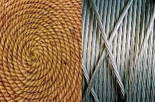
Rope driveis used where a large amount of power is needed to transfer for a long distance (more than 8m). The rope runs over a grooved pulley.
There are two types rope drive Fibres Rope and Wire Rope.
Advantages of the rope drive
- Significant power transmission.
- It can be used for long distance.
- Ropes are strong and flexible.
- Provides smooth and quiet operation.
- It can run any direction.
- Low-cost and economic.
- Precise alignment of the shaft not required
Disadvantages of the rope drive
- Internal failure of the rope has no sign on external, so it if often get unnoticed.
- Corrosion of wire rope.
How is rope drive different from Belt drive and Chain drive?
A Rope Drive uses a rope to transmit power from one system to another, for e.g in pulleys over a well. It is different from a belt drive because it does not use a belt to transmit power. A rope drive is expected to give a smoother operation and less noise than chain drive, but can have higher power losses.
Length of Open belts drive:
We have discussed that in an open belt drive, both the pulleys rotate in the same direction as shown in Fig. 1.
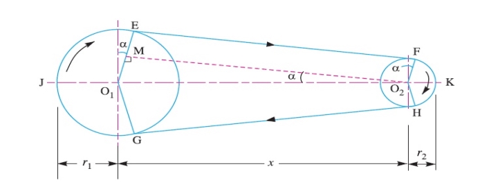
Let r1 and r2 = Radii of the larger and smaller pulleys,
x = Distance between the centres of two pulleys (i.e. O1O2), and
L = Total length of the belt.
Let the belt leaves the larger pulley at E and G and the smaller pulley at F and H as shown in Figure. Through O2 draw O2M parallel to FE.
From the geometry of the figure, we find that O2M will be perpendicular to O1E.
Let the angle MO2O1 = α radians.
We know that the length of the belt,
L = Arc GJE + EF + Arc FKH + HG
= 2 (Arc JE + EF + Arc FK) ……………………..(i)
From the geometry of the figure, we also find that
Sinα = O1M/O1O2 = O1E – EM / O1O2 = r1– r2 / x
Since the angle α is very small, therefore putting
sin α = α (in radians) = r1– r2 / x …………………….(ii)
∴ Arc JE = r1 (π/2 + α) ………………………….(iii)
Similarly, arc FK = r2 (π/2 – α) ……………………..(iv)
And EF = MO2 = [(O1O2)2 – (O1M)2]0.5
= [x2 – (r1 – r2)2]0.5
= x [1 – {(r1-r2) /x }2 ]0.5
Expanding this equation by binomial theorem, we have
EF = x [1 – {0.5 {(r1 – r2)/x} + …] = x – (r1 – r2)2 /2x …………………..(v)
Substituting the values of arc JE from equation (iii), arc FK from equation (iv) and EF from equation (v) in equation (i), we get
L = 2 [r1(π/2 +α) + x – {(r1-r2)2/2x} + r2(π/2 -α)]
= 2 [{r1 × π/2} + {r1×α} + x – {(r1- r2)2/2x} + {r2×π/2} - {r2×α}]
= 2 [π/2(r1+r2) + α(r1-r2) +x – {(r1-r2)2/2x}]
= π(r1+r2) + 2α(r1-r2) +2x – {(r1-r2)2/x}
Substituting the value of α = (r1-r2)/x from equation (ii), we get
L = π(r1+r2) + 2{(r1-r2)/x}{(r1-r2)} +2x – {(r1-r2)2/x}
= π(r1+r2) + 2{(r1-r2)2/x} + 2x – {(r1-r2)2/x}
= π (r1 + r2) + 2x + (r1 – r2 )2 /x ……………. (in terms of pulley radii)
= π/2 (d1 + d2) + 2x + (d1 – d2)2 /4x …… (in terms of pulley diameters)
Length of cross belt drive:
We have discussed that in a cross belt drive, both the pulleys rotate in the opposite directions as shown in Fig
Let r1 and r2 = Radii of the larger and smaller pulleys,
x = Distance between the centres of two pulleys (i.e. O1O2 ), and
L = Total length of the belt.
Let the belt leaves the larger pulley at E and G and the smaller pulley at F and H as shown in Figure.
Through O2 draw O2M parallel to FE.
From the geometry of the figure, we find that O2M will be perpendicular to O1E.
Let the angle MO2O1 = α radians.
We know that the length of the belt,
L = Arc GJE + EF + Arc FKH + HG
= 2 (Arc JE + FE + Arc FK) …………………(i)
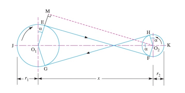
From the geometry of the figure, we find that
Sinα = O1M/O1O2 = (O1E + EM)/O1O2 = r1+r2 / x
Since the angle α is very small, therefore putting sinα = α (in radians = r1+r2 / x ………………………….…(ii)
Arc JE = r1 (π/2 + α) ……………. ……(iii)
Similarly, arc FK = r2 (π/2 + α) ………………(iv)
EF = MO2 = [(O1O2 )2 – (O1M)2]0.5
= [x2 – (r1 + r2 )2]o.5
= x [1- (r1+r2 /x )2]0.5
Expanding this equation by binomial theorem, we have
EF = x [1- 1/2(r1+r2 /x)2 + …] = x – [(r1+r2)2/2x] ……………………(v)
Substituting the values of arc JE from equation (iii), arc FK from equation (iv) and EF from equation (v) in equation (i), we get,
L = 2 [r1(π/2 +α) + x – {(r1+r2)2/2x} + r2(π/2 +α)]
= 2 [{r1 × π/2} + {r1×α} + x – {(r1+r2)2/2x} + {r2×π/2} + {r1×α}]
= 2 [π/2(r1+r2) + α(r1+r2) +x – {(r1+r2)2/2x}]
= π(r1+r2) + 2α(r1+r2) +2x – {(r1+r2)2/x}
Substituting the value of α = (r1+r2)/x from equation (ii), we get
L = π(r1+r2) + 2{(r1+r2)/x}{(r1+r2)} +2x – {(r1+r2)2/x}
= π(r1+r2) + 2{(r1+r2)2/x} + 2x – {(r1+r2)2/x}
= π (r1+r2) + 2x + (r1+r2)2 /x …………… (In terms of pulley radii)
= π/2(d1+d2) +2x + (d1 + d2)2/ 4x …………(in terms of pulley diameters)
A gear is a kind of machine element in which teeth are cut around cylindrical or cone shaped surfaces with equal spacing. By meshing a pair of these elements, they are used to transmit rotations and forces from the driving shaft to the driven shaft. Gears can be classified by shape as involute, cycloidal and trochoidal gears. Also, they can be classified by shaft positions as parallel shaft gears, intersecting shaft gears, and non-parallel and non-intersecting shaft gears.
Types of Gears
Following are the different types of gears:
- Parallel gears
- Spur Gears
- Helical Gears
- Double Helical or Herringbone Gears.
- Intersecting gears
- Spiral gears
- Bevel Gears
- Non-intersecting and Non-Parallel gears.
- Worm Gears
- Rack and Pinion gears
1) Parallel gears - As indicated by the name, parallel configurations involve gears connected to rotating shafts on parallel axes within the same plane. The rotation of the driving shaft (and the driving gear) is in the opposite direction to that of the driven shaft (and driven gear), and the efficiency of power and motion transmission is typically high.
a) Spur gear:
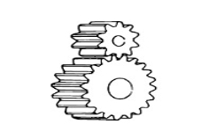
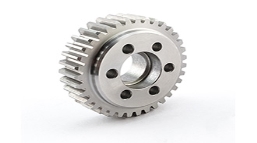
Spur gears transmit power through shafts that are parallel. The teeth of the spur gears are parallel to the shaft axis. This causes the gears to produce radial reaction loads on the shaft, but not axial loads. Spur gears tend to be noisier than helical gears because they operate with a single line of contact between teeth. While the teeth are rolling through mesh, they roll off of contact with one tooth and accelerate to contact with the next tooth. This is different than helical gears, which have more than one tooth in contact and transmit torque more smoothly.
b) Helical Gear:

Helical gears have teeth that are oriented at an angle to the shaft, unlike spur gears which are parallel. This causes more than one tooth to be in contact during operation and helical gears are capable of carrying more load than spur gears. Due to the load sharing between teeth, this arrangement also allows helical gears to operate smoother and quieter than spur gears. Helical gears produce a thrust load during operation which needs to be considered when they are used. Most enclosed gear drives use helical gears.
c) Double Helical Gear:

Double helical gears are a variation of helical gears in which two helical faces are placed next to each other with a gap separating them. Each face has identical, but opposite, helix angles. Employing a double helical set of gears eliminates thrust loads and offers the possibility of even greater tooth overlap and smoother operation. Like the helical gear, double helical gears are commonly used in enclosed gear drives.
d) Herringbone Gear
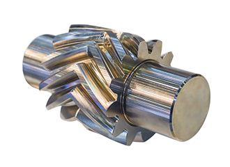
Herringbone gears are very similar to the double helical gear, but they do not have a gap separating the two helical faces. Herringbone gears are typically smaller than the comparable double helical, and are ideally suited for high shock and vibration applications. Herringbone gearing is not used very often due to their manufacturing difficulties and high cost.
2) Intersecting gears
Bevel gear: Bevel gears are most commonly used to transmit power between shafts that intersect at a 90 degree angle. They are used in applications where a right angle gear drive is required. Bevel gears are generally more costly and are not able to transmit as much torque, per size, as a parallel shaft arrangement.
Bevel gear transmits power between two intersecting shafts at any angle or non-intersecting shaft. They are classified as straight and spiral tooth bevel and hypoid gears. These are gears cut from conical blanks and connect intersecting shaft axes.
The connecting shaft is generally at 90°and sometimes one shaft drives a bevel gear which is mounted on a through the shaft resulting in two output shafts. The point of intersection of the shaft is called the apex and the teeth if the two gears converge at the apex.
There are several types of bevel gears available differentiated mainly by their tooth design. Some of the more common types of bevel gears include straight, spiral, and Zero bevel gears.
a) Straight Bevel Gears
The most commonly used of the bevel gear tooth designs due to its simplicity and, consequently, its ease of manufacturing, straight bevel teeth are designed such that when properly matched straight bevel gears come into contact with one another, their teeth engage together all at once rather than gradually. As is the issue with spur gears, the engagement of straight bevel gear teeth results in high impact, increasing the level of noise produced and amount of stress experienced by the gear teeth, as well as reducing their durability and lifespan.
b) Spiral Bevel Gears
In spiral bevel gears, the teeth are angled and curved to provide for more gradual tooth engagement and more tooth-to-tooth contact than with a straight bevel gear. This design greatly reduces the vibration and noise produced, especially at high angular velocities (>1,000 rpm). Like helical gears, spiral bevel gears are available with right-hand or left-hand angled teeth. As is also the case with helical gears, these gears are more complex and difficult to manufacture (and, consequently, more expensive), but offer greater tooth strength, smoother operation, and lower levels of noise during operation than straight bevel gears.
Additional Bevel Gear Designs
Other than the types mentioned above, there are several other designs of bevel gears available including miter, crown, and hypoid gears.
c) Miter: Miter gears are bevel gears which, when paired, have a gear ratio of 1:1. This gear ratio is a result of pairing two miter gears with the same number of teeth. This type of bevel gear is used in applications which require a change only to the axis of rotation with speed remaining constant.When two bevel gear has their axes at right angles and is equal sizes, they are called mitre gears.
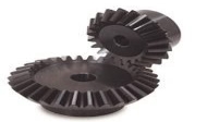
d) Crown: Crown gears, also referred to as face gears, are cylindrical (rather than conical) bevel gears with teeth cut or inserted perpendicular to the gear face. Crown gears can be paired either with other bevel gears or, depending on the tooth design, spur gears.
e) Hypoid: Originally developed for the automobile industry, hypoid gears, unlike the previously mentioned types, are a type of spiral bevel gear used for non-parallel, non-intersecting configurations. This design allows for components to be placed lower, allowing for more space in the sections above. Employing curved and angled teeth similar to those used in spiral bevel gears, hypoid gears are even more complex and, consequently, more difficult (and costly) to manufacture.
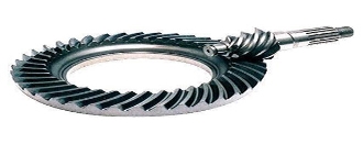
Hypoid gears look very much like a spiral bevel gear but they operate on shafts which do not intersect, which is the case with a spiral bevel gear. In the hypoid arrangement because the pinion is set on a different plane than the gear, the shafts are supported by the bearings on either end of the shaft.
3) Non-intersecting and Non-Parallel gears.
a) Worm Gears:
Worm gear pairs are comprised of a worm wheel typically a cylindrical gear paired with a worm i.e., a screw-shaped gear. These gears are used to transmit motion and power between non-parallel, non-intersecting shafts. They offer large gear ratios and capabilities for substantial speed reduction while maintaining quiet and smooth operation.
Worm gears transmit power through right angles on non-intersecting shafts. Worm gears produce thrust load and are good for high shock load applications but offer very low efficiency in comparison to the other gears. Due to this low efficiency, they are often used in lower horsepower applications.
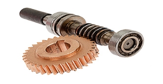
One distinction of worm gear pairs is that the worm can turn the worm wheel, but, depending on the angle of the worm, the worm wheel may not be able to turn the worm. This characteristic is employed in equipment requiring self-locking mechanisms. Some of the disadvantages of worm gears are the low transmission efficiency and the amount of friction generated between the worm wheel and worm gear which necessitates continuous lubrication.
4) Rack and Pinion Gears
A rack and pinion is pair of gears which convert rotational motion into linear motion and vice versa. A circular gear called “the pinion” engages teeth on a linear “gear” bar called “the rack”.
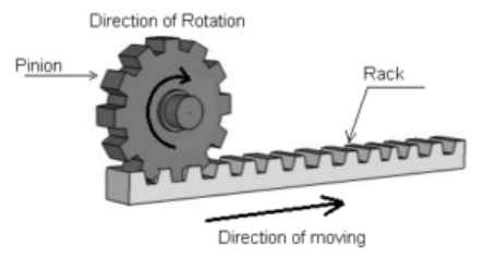
Rotational motion applied to the pinion will cause the rack to move to the side, up to the limit of its travel. The diameter of the gear determines the speed that the rack moves as the pinion turns.
A rack and pinion is commonly found in the steering mechanism of cars or other wheeled, steered vehicles. In a rack railway, the rotation of a pinion mounted on a locomotive or a railcar engages a rack between the rails and pulls a train along a steep slope, machine tools such as lathe machine, drilling machine, planning machine.
Rack and pinion gears are a pair of gears comprised of a gear rack and a cylindrical gear referred to as the pinion. The gear rack can be considered as a gear of infinite radius (i.e., a flat bar) and is constructed with straight teeth cut or inserted on the bar’s surface. Depending on the type of pinion gear with which it is mated, the gear rack’s teeth are either parallel (when mated with spur gears) or angled (when mated with helical gears). For either of these rack designs, rotational motion can be converted into linear motion or linear motion can be converted into rotational motion.
Some of the advantages of a rack and pinion gear pair are the simplicity of the design (and the low cost of manufacturing) and high load carrying capacities. Despite the advantages of this design, gears which employ this approach are also limited by it. For example, transmission cannot continue infinitely in one direction as motion is limited by the designated length of the gear rack. Additionally, rack and pinion gears tend to have a greater amount of backlash (i.e., additional space between mated gear teeth) and, consequently, the teeth experience a significant amount of friction and stress.
Some of the common applications of rack and pinion gear pairs include the steering system of automobiles, transfer systems, and weighing scales.
Types of Gear Trains
A gear train is a mechanical system formed by mounting gears on a frame. When two or more gears mesh together to transmit power from one shaft to another such arrangement is called a gear set or a gear train.
Sometimes two or more gears are made to mesh with each other to transmit power from one shaft to another such a combination is called “gear train of the wheel”. Also, each gear is generally attached to a shaft often gears that are meshed together will be of different sizes in this case the smaller gear is referred to as the pinion and the larger one is simply referred to as the gear.
Following are the different types of gear trains:
- Simple gear train
- Compound gear trains
- Reverted gear trains
- Epicyclic gear trains
1. Simple Gear Trains
In these types of gear trains, the distance between the two wheels is great. The motion from one wheel to another is transmitted by providing one or more intermediate wheels as shown in the figure.
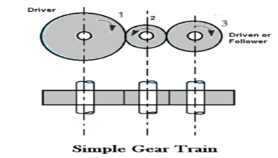
When the number of intermediate wheels is odd, the motion of driver and follower is like as shown in the figure. If the number of intermediate wheels is even the motion of the follower will be in the opposite direction of the driver as shown in the figure.
The speed ratio (or velocity ratio) of gear train is the ratio of the speed of the driver to the speed of the driven or follower and ratio of speeds of any pair of gears in mesh is the inverse of their number of teeth, therefore
Speed ratio: Speed of driver /speed of driven = NO. Of teeth on driven /No. Of teeth on driver.
Speed ratio = N1/N2 = T2 / T1
The train value may be noted that ratio of the speed of the driven or follower to the speed of the driver is known as train value of the gear train. Mathematically,
Train value: Speed of driven /speed of driver = NO. Of teeth on driver /No. Of teeth on driven.
Train value = N2 / N1 = T1 / T2
2. Compound Gear Train
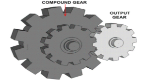
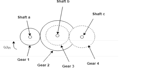
In compound gear train, each intermediate shaft has two wheels fixed to it. These wheels have the same speed. One wheel gears with the drier and the other wheel gears with the follower attached to the next shaft.
Speed ratio: Speed of first driver /speed of last driven = Product of the number of teeth on driven /product of the number of teeth on driver
Speed ratio = N1 / N6 = T2 X T4 X T6 / T1 X T3 X T5
Train value: Speed of last driver /speed of first driven = Product of the number of teeth on driver /product of the number of teeth on driven
3. Reverted Gear Trains
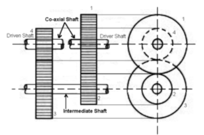
When the axes of the first and last wheels are co-axial the train is known as “reverted gear trains” as shown fig. Since the motion of the first and last wheel is alike, therefore a compound wheel is provided. Since the distance between the centres of the shaft 1 and 2 as well as 3 and 4 is the same.
Speed ratio: Speed of first driver /speed of last driven = Product of the number of teeth on driven /product of the number of teeth on drivers
Epicyclic gear train: the axes of the shaft, over which the gears are mounted, move relative to a fixed axis. A simple epicyclic or planetary gear train is shown the figure.
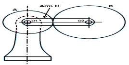
Here wheel A and arm C have a common axis at O1 about which they can rotate. The wheel B meshes with wheel A and has its axis on the arm at O2, about which the wheel B can rotate. If wheel A is fixed and the arm is rotated, the train becomes an “epicyclic gear train”.
The Clutch is the most important part of the engine in an automobile. A clutch uses to transfer rotating motion or torque from one shaft to another shaft when requires. The torque developed by the engine at the initial speed is very low. Therefore it is impossible to start the engine under load.
It requires that the transmission system should provide a means of connecting and disconnecting the engine from the rest of the transmission system. Such an operation must be smooth and without shock to the passengers of the vehicle.Hence a device that uses to engage and disengage the engine from the transmission system is called a clutch.
The clutch permits the gradual taking of load when adequately operated, thereby it prevents jerky motion of the vehicle, and this avoids undue strain on the parts of the vehicle as well as passengers.In the transmission system, the system by which power developed by the engine is transmitted to road wheels to propel the vehicle.
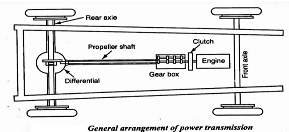
In automobiles, the power is developed by the engine which is used to turn wheels. Therefore, the engine is to be connected to the transmission systems for transferring power to wheels.
Also, there should be a system using which the engine could be engaged and disengaged with the transmission system smoothly and without shock so that the vehicle mechanism is not damaged and passengers do not feel inconvenience. A clutch is employed in automobiles for this purpose.
PARTS OF CLUTCH
The clutch consists of the following parts. We will discuss it in detail.
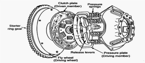
1. Flywheel
The flywheel is an integral part of the engine, which also use as a part of the clutch. It is a driving member and connects to the pressure plate of the clutch shaft is houses with bearings in a flywheel. The flywheel rotates as the engine crankshaft rotates.
2. Pilot Bearing
The pilot bearing or bushing press into the end of the crankshaft to support the end of the transmission input shaft.
The pilot bearing prevents the transmission shaft and clutch disc from wobbling up and down when the clutch releases. It also assists the input shaft center of the disc on the flywheel.
3. Clutch plate or Disc plate
It is the driven member of the single-plate clutch and line with friction material on both surfaces. It has a central hub with internal splines to limit the axial travel along the splined gearbox driving shaft.
This helps to provide damping actions against torsional vibrations or variations of the driving torque between engine and transmission.A clutch disc is a plate between flywheel and friction or pressure plate. It has a series of facings inverters on each side to enlarge the friction. These clutch facings are made of asbestos material. They are highly worn and heat resistant.
4. Pressure plate
The pressure plate is made of special cast iron. It is the heaviest part of the clutch assembly. The main function of the pressure plate is to establish even contact with the driven plate facing through which the pressure springs can exert a sufficient force to transmit the full torque of the engine.
The pressure plate presses the clutch plate on to the flywheel from its machined surface. Between the pressure plate and clutch cover assembly, pressure springs are fits. The pressure will be withdrawn from the flywheel whenever release levers depress by the toggle or release levers pivots accordingly.
5. Clutch cover
The clutch cover assembly bolts to the flywheel. It consists of a pressure plate, release lever mechanism, clutch cover, and pressure springs. Generally, the clutch plate revolves with the flywheel.
However, when the clutch has disengaged, the flywheels, as well as the pressure plates are free to rotate independently from the driven plate and driving shaft.
6. Release levers
These pivots on pins to the clutch cover, their outer ends locate and positions on pressure plate legs and the inner ends are projecting towards the clutch shaft. A careful and accurate adjustment of the release mechanism is one of the most important factors governing the performance of a clutch assembly.
7. Clutch shaft
It is a component of the gearbox. Since it is a splined shaft to the hub of the clutch plate, which is sliding on it. One end of the clutch shaft attaches to the crankshaft or flywheel and the other end connects to the gearbox or forms a part of the gearbox.
WORKING OF CLUTCH
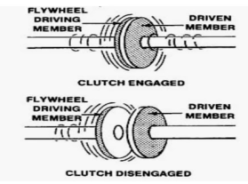
A Clutch is defined as a system that is used to connect or disconnect the engine from the rest of the transmission elements.
It is located between the engine and gearbox. During normal running and stationary position, it is always in the engaged condition.
The clutch disengages when the driver processes the clutch pedal. The clutch disengages for starting, changing gears, stopping, and idling.
When the clutch engages, the engine will connect to the transmission, and power flows from the engine to rear wheels through a transmission system When the clutch disengages by pressing the clutch pedal, the engine will disengage from the transmission. Thus, the power does not flow to rear wheels while the engine is still running.
NECESSITY OF CLUTCH IN AUTOMOBILE
The clutch is a device that is necessary to transmit power from the engine to the wheels of the vehicle by engaging the engine to the transmission system gradually without giving the jerks to the body of the vehicle.
PRINCIPLES OF CLUTCH

The clutch works on the principle of friction. In Figure, the driving shaft A with flange C is rotating at 'N' rpm, and shaft B with the flange D is keyed to the driven shaft which is in a stationary position when the clutch is not engaged. Now, an external force is applied to the flange D so that it comes in contact with flange C.
As soon as the contact is made, they are united due to friction between them and the flange D starts rotating with flange C.
The rotational speed of flange D depends on the friction between surfaces C and D which in turn is proportional to the external force applied.
If the force gradually increases, the speed force transmitted will also increase gradually. The torque transmitted by the friction clutch depends on the pressure applied on the flange, coefficient of friction of the surface materials, and radius of the flange. By increasing any of them, the force transmitted can increases.
FUNCTIONS OF CLUTCH
1. To allow the engagement or disengagement of gear when the vehicle is stationary and the engine is running.
2. To transmit the engine power to rear wheels smoothly without shocks to the transmission system when the vehicle is in motion.
3. To permit the engaging of the gears when the vehicle is in motion without damaging gear wheels.
READ | What Is Multi-Plate Clutch - Types, Working, Pros & Cons, and Diagram
REQUIREMENTS OF A CLUTCH
A clutch must have the following requirements.
1. The clutch should be able to engage gradually and positively without the occurrence of sudden jerks.
2. It should be capable of transmitting maximum torque to the engine.
3. The design of the clutch is such that it should ensure the dissipation of heat sufficiently which is generated during operation.
4. The clutch should dynamically balance to the vibration in the transmission system. It is a very important requirement in modern cars which operate at high speed.
5. The size of the clutch should be as small as possible so that it will occupy minimum space.
6. The suitable mechanism should incorporate within the clutch for damping of vibration and elimination of noise produces during the transmission.
7. To reduce effective clamping load on the car thrust bearing as well as wear on it, a provision should be made for clutch-free pedal play.
8. The clutch must have the non-tiresome operation of disengagement for the driver for higher power transmission.
TYPES OF CLUTCHES
The clutches used in motor vehicles are almost similar in construction and operation. There are individual differences in the details of their linkages as well as in the pressure plate assemblies.
DIFFERENT TYPES OF CLUTCHES ARE CLASSIFIED AS FOLLOWS
- Friction Clutch - Single Plate Clutch | Multi-Plate Clutch - Wet Clutch & Dry Clutch | Cone Clutch
- Centrifugal clutch
- Semi-centrifugal clutch
- Hydraulic clutch
- Conical spring clutch or Diaphragm clutch
- Positive clutch or Dog and Spline Clutch
- Vacuum clutch
- Electromagnetic clutch
APPLICATIONS OF CLUTCH
Clutches have various applications according to their types. The clutch not only uses for automobile purposes but also for industrial purposes.
Automobile Use - Heavy vehicles, four-wheelers such as cars, trucks, buses, Two-wheelers, mopeds, scooters, bikes.
Industrial Use - Metal stamping, Press working, Packing machines, Indexing tables, Assembling machines, Printing machines, Conveyor belts, Pumps, Gear drives.
Disc clutch
A clutch disc is a part of a manual transmission, also known as the friction lining. It is in between the pressure plate and the flywheel, mainly composed of two things the splined hub and a metal plate where you can find friction linings. The main purpose of it is to help the splines from the center to work or get engaged with the splines on the input shaft. Because of that, the input shaft and disc will turn together, while the disc can still slide back and forth on the shaft.
If you will look closely, you will find small coil springs right between the friction disc and the clutch disc splined hub. These are called the torsion spring or damping spring. When a clutch engagement happens, these torsion springs will absorb the vibrations or the shocks that may possibly be produced. On the other hand, those flat coil springs under the friction lining are called the facing spring or cushioning springs. These are responsible for smooth engagements and to help the lining flex slightly during the initial engagement.
The clutch disc has several protections to ensure that it won’t be damaged under stressful circumstances. The disc lining is made of cotton fibers, copper wires and heat-resistant asbestos.
Centrifugal clutch
A centrifugal clutch is a mechanical device which is used on driven rotary equipment. Most commonly used with a combustion engine, the clutch can be used to automatically transmit the torque from the drive to the driven equipment giving a “soft start” with no load engagement. By using this type of clutch between the drive and the driven equipment the speed at which the mechanical driven shaft engages can be controlled. As the engine speed is increased to or above the set engagement speed of the centrifugal clutch the mechanical drive will become engaged. This enables the operator to run the engine at a designated idling speed without driving the equipment, thus allowing the engine to reach its optimal torque before experiencing load.
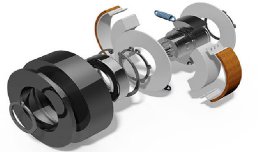

Advantages And Disadvantages Of Using A Centrifugal Clutch
Using a centrifugal clutch on engine driven equipment enables the engine to be started under a no-load situation. When the engine is idling the drive remains disengaged. Only when the rpm of the engine is increased to the set engagement speed of the clutch or above will the drive be fully connected. This results in a smooth engagement and prevents the engine from stalling. It also helps protect the engine by ensuring high levels of torque are not transmitted back through the flywheel of the engine. In circumstances such as this, for example when the rotating equipment is for some reason jammed, the extreme levels of torque transmitted back through the engine can cause significant and in some cases irreparable damage to the engine. This can be a very costly and sometimes economically unfeasible to repair the equipment. By using a centrifugal clutch, this can be avoided as the components of the clutch will take the overload. The wearing parts of a clutch are easy and cost effective to replace. In addition to providing a no-load situation the set engagement speed of the clutch also allows the operator to control at what point the rotary equipment becomes engaged. This allows the engine of the machinery to be running but without necessarily operating.
Due to the nature of centrifugal clutch being a purely mechanical automatic engagement at a pre-determined speed, each application may require a specific configuration. Meaning this pre-set engagement speed cannot be changed without altering internal components.
How Does A Centrifugal Clutch Work?
A centrifugal clutch works, as the name suggests, through centrifugal force. The key components of a centrifugal clutch are the hub, flyweights (clutch shoes), springs, linings and housing (shown in the diagram below). The centrifugal force, created by the revolutions of the engine is transmitted through two or more flyweights. The clutch can be driven by a number of ways depending upon the design of the machinery. One of the most common methods is by mounting the clutch onto the parallel or taper crank shaft of the engine. When the crank shaft rotates the shaft of the clutch rotates at the same speed as the engine. The rotation of the hub forces the shoes or flyweights outwards until they come into contact with the clutch drum, the friction material transmits the torque from the flyweights to the drum. The drive is then connected. The springs, flyweights and the friction material are responsible for determining the speed at which the clutch engages. Depending on the design of the machine the output from the clutch can be one of a variety drives, including but not limited to shaft, pulley, sprocket or flange.
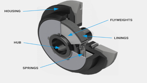
Centrifugal Clutch Applications
A centrifugal clutch can be useful for a range of engine driven equipment with a high starting inertia. They are commonly found on mobile equipment with rotating parts that are driven by small diesel or petrol engines. Some of these examples include:
- Vibratory plate compactors and rollers
- Rammers
- Compressor/vacuum/fan drives
- Trowel and concrete finishers
- Compact road/street cleaners
- Transport refrigeration units
- Mobile water pumps
- Ground care equipment – rotary and flail mowers, turf cutters and scarifies
- Go-karts
- Woodchoppers/stump grinders/milling cutters