Unit 1
Introduction to Mechanics
Mechanics is the physical science concerned with the behaviour of bodies that are acted upon by forces.Mechanics is a branch of the physical sciences concerned with the state of rest or motion of bodies that are subjected to the action of forces. The study of mechanics involves many more subject areas. However, initial study is usually split into two areas; statics and dynamics.
Statics is concerned with bodies that are either at rest or move with a constant speed in a fixed direction. Dynamics deals with the accelerated motion of bodies. Statics can therefore be considered as a special case of dynamics where the acceleration is zero. In engineering, since many objects are designed with the intention that they are at rest or their motion remains constant, statics deserves special treatment.
Statics is the study which deals with the condition of bodies in equilibrium subjected to external forces.
In other words, when the force system acting on a body is balanced, the system has no external effect on the body, the body is in equilibrium.
Dynamics is also a branch of mechanics in which the forces and their effects on the bodies in motion are studied. Dynamics is sub-divided into two parts: (1) Kinematics and (2) Kinetics
Kinematics deals with the geometry of motion of bodies without and application of external forces.
Kinetics deals with the motion of bodies with the application of external forces.
Hydromechanics is the study which deals with the conditions of fluid under which it can remain at rest or in motion. Hydromechanics can be divided into hydrostatics and hydrodynamics.
Hydrostatics is the study of fluid at rest.
Hydrodynamics is the study of fluid in motion.
- A body is said to be rigid if it retain its shape and size even if the external forces are applied on it. It is called a rigid body.
Scalars and vectors
In mechanics, as elsewhere, some quantities are scalar quantities and some are vector quantities. It is important to understand the difference between the two.
Scalars
Scalar quantities are quantities that only have a magnitude (size). Scalar quantities are useful, but for some quantities in mechanics we need more information; to this end we introduce vectors.
Vectors
Vector quantities are quantities that possess direction, as well as magnitude. Vectors are usually referred to in bold type
Basic concepts
Basic quantities
Time is the measure of a succession of events and is a basic quantity in dynamics. Time is not involved in the analysis of statics problems. Time is a scalar quantity.
Length is needed to locate the position of a point in space and describes the size of a physical system. Once a standard unit of length has been defined, it is possible to define distances and geometric properties of a body as a multiple of the unit of length. Length is a scalar quantity.
Volume is a measurement of the physical size of an object. It refers to how much space an object takes up. Volume is a scalar quantity.
Mass: is a measure of the translational inertia of the body, which is its resistance
To a change in velocity Mass can also be thought of as the quantity of matter in a
Body. The mass of a body affects the gravitational attraction force between it and other bodies. The concept of mass is used to characterize and compare two bodies on the basis of certain fundamental mechanical experiments depending on the definitions given above.
Density is related to mass and volume. It is defined as the mass per unit volume. This means that an object that has a large mass but a small volume will have a large density. Density is a scalar quantity.
Speed is a measure of how quickly a body is moving. It is defined as distance travelled per unit time. Speed is a scalar quantity.
Forces are influences on a body or system which, acting alone, would cause the motion of that body or system to change. A system or body at rest and then subjected to a force will start to move. To work with forces we need to know the magnitude (size), direction and the point of application of the force. Forces are vector quantities.
Displacement is a measure of distance in a particular direction. Displacement is a vector quantity.
Velocity is the rate of change of displacement with respect to time. Velocity is a vector quantity.
Acceleration is the rate of change of velocity with respect to time. Acceleration is a vector quantity.
Momentum is defined as the product of an object’s mass and its velocity. This is a very important quantity in mechanics. It arises in many problems particularly those involving collisions. Momentum is a vector quantity.
Space: is the geometric region occupied by bodies whose positions are described by linear or angular measurements relative to a specific coordinate system. For three dimensional problems, three independent coordinates are needed. For two dimensional problems only two coordinates will be required.
Idealisations
In mechanics we look at real life situations and try to predict what will happen. The problem with real life is that it is often quite complicated. When studying problems in mechanics we often make idealisations of real life situations that simplify the problem. There are many commonly used idealisations that we will introduce in later sheets. Here follows a list of some common idealisations that are used in mechanics.
Particles are bodies which can be treated as a point mass in a given context. For example, when modelling the motion of the planets around the Sun, the planets and Sun can be treated as particles. Much of basic mechanics study is concerned with objects that can be treated as particles.
Connected particles arise in problems where two objects are attached in some way and both objects can be treated as particles. For example, two masses, connected by a string which passes over a pulley could be modelled as connected particles.
Rigid bodies can be considered as combinations of particles in which all the particles remain at a fixed distance from one another both before and after applying a force i.e. there is no bending or stretching. For example a brick can in most circumstances be thought of as a rigid body. Many real life objects can be considered to be rigid bodies to a good approximation.
Fundamental concept
Certain concepts and definitions are basic to the study of mechanics and they should be understood at the outset. The basic concepts in mechanics are space, time, mass and force. These concepts cannot be truly defined. They should be accepted on the basis of our intuition and experience, and used as a mental frame of reference for our study of mechanics.
In Newtonian mechanics, space, time and mass are absolute quantities, which mean that they are independent of each other (this is not true in RelativisticMechanics, where the time of an event depends upon its position and the mass of
a body varies with its velocity) and cannot be defined in terms of other quantities
Or in simpler terms. Force is a derived quantity.
For example:
1) Two bodies of the same mass will be attracted by the Earth in the same manner.
2) They will also offer the same resistance to a change in translational motion.
Forces and Force system
ACTIONS AND EFFECTS OF FORCES
A force is defined as the action of a body on another body. A force is applied either through a direct contact or through a remote action. Forces applied through a remote action are gravitational, electrical, and magnetic forces. All other forces are applied through direct contacts.
Force acting on a body produces effects that can be divided into two types, namely external effect and internal effect.
As an illustration, consider the structure portrayed Assume that the structure is of negligible mass. The applied force F acting on the structure causes the reactive forces R1 and R2 which are applied by the support surfaces onto the structure so as to balance F. The reactions R1 and R2 are effects external to the body which are caused by F. Hence, external forces acting on a body are of two types, namely applied external forces (also called active forces) and reactive forces.
Besides causing the reactions R1 and R2, the applied force F also causes effects internal to the members of the structure. These effects are in the forms of stresses and strains that appear in the material of the structure. The effects exist to balance the respective external actions and effects.
In the study of mechanics, only the external effects of a force are considered. The internal effects are studied in disciplines of study specific to them, for example Mechanics of Materials (also known as Strength of Materials).
FORCE DISTRIBUTION
Any force applied to a body will act on a finite area of application. The force is distributed over the area of application. In many cases, the area of application is extremely small compared to the dimensions of the body being upon acted by the force. In such cases, the dimension of the area of distribution can be neglected and the area of application can be considered as a point. A force acting on such a point of action is called a concentrated force. The tension of the cable of the crane is a concentrated force.
If the dimension of the area of application of a force cannot be neglected, we obtain a distributed force which acts either a line, an area, or a volume. The push of the wind acting on the sign board in Figure 2.2(b) ia a distributed force.
The effect of a distributed force depends on the nature of distribution of the force. .
FORCES AS A VECTOR QUANTITY
A concentrated force is a vector quantity. This has been determined through experiments which show that concentrated forces add-up according to the parallelogram law and when a concentrated is applied to a body, the effect depends on the magnitude, direction, and point of application of the force. Hence, mathematical analyses of a concentrated force are based on the mathematical rules of vectors (see Appendix).
MAGNITUDE AND DIRECTION OF A FORCE
The magnitude of a force is a scalar quantity. In the SI system, it is measured in the unit newton (N). Force acting on a body is illustrated graphically by a vector arrow at the point of application of the force, where the orientation of the arrow represents the direction of the line of action of the force whilst the arrow head represents the sense of the force, Figure 2.3. A force is fully defined once its magnitude, direction, sense, and point of application is specified.
The magnitude, direction, and sense of a force F can be represented fully by a mathematical expression using a unit vector s which corresponds to line of action and sense of the force. For example, the force F in Figure 2.4 has a magnitude F. Its direction of action corresponds to that of the unit vector s. Hence F can be written as F=Fs.
Characteristics of force:
- Force can introduce motion in a body.
- Force can change direction of a moving body.
- Force can change size of an object.
- Force is a vector quantity.
- Force can stop a moving body.
- Force has a unit of Newton(N) in M.K.S system and dyne in C.G.S system.
- They are of two types: contact and non-contact forces.
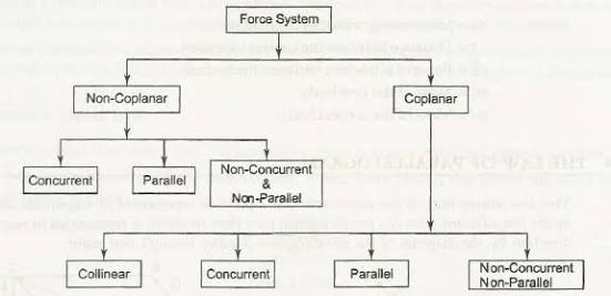
Force system is a collection of forces acting at specified locations.
Different types of force system:
(i) COPLANAR FORCES:
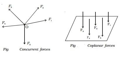
Forces acting on only one plane areknown as coplanar force system.
Or, we can say that if the effect of forces is only in one plane of object then the force system is known as coplanar force.
Ii) CONCURRENT FORCES:
A concurrent coplanar force system is a system of two or more forces whose lines of action ALL intersect at a common point.
Iii) LIKE FORCES
Parallel coplanar force system consists of two or more forces whose lines of action are all parallel to one another.
Iv) UNLIKE FORCES:
If the parallel forces are such that their directions are opposite to each other, then they are termed as "UNLIKE FORCE".

Principles of Statics
Statics is a branch of mechanics which studies the effects and distribution of forces of rigid bodies which are and remain at rest. In this area of mechanics, the body in which forces are acting is assumed to be rigid. The deformation of non-rigid bodies is treated in Strength of Materials.
- Resultant of Force System
- Equilibrium of Force System
- Analysis of Trusses
- Cables
- Friction
- Centroids and Centers of Mass
- Moments of Inertia
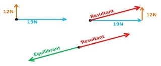
Equilibrant forceis equal in magnitude but opposite in direction to the resultant force of all the forces acting on a body.
- Equilibrant force= - resultant force
- R=√[(a^2+b^2+2abcos@)]
- R=√[(60)^2+(40)^2)+2*60*40*cos(90°)]
- R=√5200
- R=72.112
If two forces are equal in opposite directions, each force is the equilibrant of the other. The equilibrant force is labelled as FQ is equal in magnitude but opposite in direction to the resultant vector. (FQ = -FR)
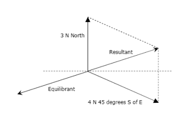
The equilibrant force is the single force that if applied at the same point (equal in magnitude and opposite on direction) that produces equilibrium.
Resultant force
When an object is subject to several forces, the resultant force is the force that alone produces the same acceleration as all those forces.
For example, if 4 forces act on a block and cause it to accelerate 1 m/s2 south, then the resultant force is the force that, if applied alone to the block, will also make it accelerate 1 m/s2 south.
The reason why the resultant force is useful is that it allows us to think about several forces as though they were a single force. This means that to determine the effect that several forces have on an object, we only need to determine the effect that a single force has.
If we know the mass m of an object and the acceleration a produced by the forces that act on it, we can find the resultant force using Newton's Second Law. Indeed, according to Newton's Second Law, the force F that alone produces the acceleration a on an object of mass m is:
F = ma
This force F is our resultant force. So, we can write:
R = ma
Which indicates that the resultant force R has the same direction as a, and has magnitude equal to the product ma.
For example, if a box of 1.5 kg is subject to 5 forces which make it accelerate 2.0 m/s2 north-west, then the resultant force is directed north-west and has the magnitude equal to 1.5 kg × 2.0 m/s2 = 3.0 N.
Often, however, we know the forces that act on an object and we need to find the resultant force. Experiments show that when an object is subject to several forces, F1, F2 the resultant force R is the vector sum of those forces:
R = F1 + F2 +…
Notice that this is not a mere sum of the magnitudes of the forces, but the sum of the forces taken as vectors, which is more involved because vectors have both a magnitude and a direction that we need to consider when doing the sum.
According to the above equation, if an object is subject to no forces, then the resultant force is zero, and if an object is subject to only one force, then the resultant force is equal to that force. These two cases are pretty simple, but what about an object subject to two or more forces.
To explain this clearly, we will now go through all the cases that can happen, from simple ones in which all the forces are parallel, to more complex ones in which the forces are not parallel, and show how to find the resultant force in each of them with the help of examples.
Resolution and composition of forces
Resolution of a Force
The process of substituting a force by its components so that the net effect on the body remains the same is known as resolution of a force.
- For each force, there exist an infinite number of possible sets of components.
Suppose a force is to be resolved into two components. Then:
- When one of the components is known, the second component can be obtained by applying the triangle rule.
- When the line of action of each component is known, the magnitude and the sense of the components are obtained by parallelogram law.
Principle of Resolution
The algebraic sum of the resolved parts of a number of forces in the given direction is equal to the resolved part of their resultant in the same direction.
Composition of Forces
The process of finding out the resultant force of a number of given forces is called the composition/compounding of forces.
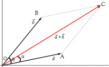
Parallelogram Law
"If two forces acting simultaneously on a particle is represented in magnitude and direction by two adjacent sides of a parallelogram, their resultant may be represented in magnitude and direction by the diagonal of the parallelogram which passes through the point of intersection."
Composition:-
The process of finding out the resultant force of a given force system.
Resolution:-
It is the procedure of splitting up a single force into number of components without changing the effect of same on the body.
Forces are generally resolved into two components along two mutually perpendicular directions.
Methods of composition / methods for the Resultant force.
A Analytical Method B] Graphical Method
- Resultant of two concurrent Forces i.e. Law of Parallelogram of Force
- Resultant of more than two Forces (concurrent & non-concurrent)
Method of Resolution
Force system
Force [(F) or (P)]:-
It is an external agency which produces or tends to produce, destroy or tends to destroy motion. OR
It is an external agent which changes or tends to change the state of motion of body.
It is a vector quantity.
Force is also known as rate of change of momentum.
As momentum = mass x velocity
But mass will never change, then
Force = mass x rate of change of velocity
= mass x Acceleration
F = P = ma
S.I. Unit: - Newton (N)
Kilo Newton (KN) = 103 N
Mega Newton (MN) = 106 N
Giga Newton (GN) = 103 N
Tera Newton (TN) = 1012 N
1 Kg Force:-
Force required producing unit gravitational acceleration on unit mass.
01 kg force = mass x Acceleration (gravity)
= 1 kg x 9.81 m / s2
= 9.81 kg.m / s2
1 kg.F = 9.81 Kg m / s2
1 kg.F = 9.81 N
I.e. 1 Kg = 9.81 N
Characteristics of Force:-
1. Magnitude: - The value of force i.e. 10N, 2KN, etc.
2. Direction:- Line of action & angle formed with fixed axis.
3. Nature of force or sense:-It means whether the force is push or pull.


Pull type force Push type force
Push: - Force acting towards the point
Pull: - Force acting away from the point.
4. Point of application:-
The point at which or through which the force acts.
Effects of Force:-
Force may produce following effects on the body.
1. It may change the state of body.
i.e. if body is at rest, force may bring it in motion or if body is in motion, force may accelerate it or force may stop it or may retard it.
2. It may produce internal stress in the body.
3. It may produce deformation in non-rigid body.
4. It may produce rotational effect in body.
5. It may keep the body in stable state (Equilibrium).
Principles of Statics
Statics is a branch of mechanics which studies the effects and distribution of forces of rigid bodies which are and remain at rest. In this area of mechanics, the body in which forces are acting is assumed to be rigid. The deformation of non-rigid bodies is treated in Strength of Materials.
Resultant of two concurrent forces:-
Law of parallelogram of forces:-
If two forces acting simultaneously on a particle be represented in magnitude & direction by two adjacent sides of parallelogram, then the diagonal passing through the point of intersection of two forces will represent the resultant in magnitude & direction.
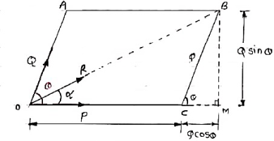
Consider two forces P & Q acting at a point represented by two sides OA & OC of parallelogram OABC.
Let, θ is the angle between two forces P & Q.
α be the angle between Force P & Resultant R.
Let’s draw a line BM perpendicular to OC which intersects OC at M.
In Δ CMB
Sin θ = BM / BC = BM / Q
BM = Q Sin θ
Also, Cos θ = CM / BC = CM / Q
CM = Q Cos θ
Now in Δ OMB,
We have, (OB) 2 = (OM) 2 + (BM)2
R2 = (OC + CM) 2 + (BM)2
R2 = (P + Q Cos θ) 2 + (Q Sin θ)2
= P2 + 2PQ Cos θ + Q2 Cos2 θ+ Q
= P2 + 2PQ Cos θ + Q2(Cos2 θ+ Q2 Sin2 θ)
= P2 + 2PQ Cos θ + Q2
 Taking sq. Root,
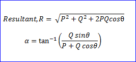
R = √P2 + Q2 + 2PQ Cos θ . . . . Magnitude

Tanα = Q Sin θ / P + Q Cos θ . . . . Direction
Resultant of more than two Forces:-
Method of Resolution
When two or more coplanar concurrent or non-concurrent forces are acting on a body, then the resultant can be found out by using resolution of forces. A resolution procedure is described below.
1. Resolve all the forces horizontally & find the algebraic sum of all the horizontal components.
If a force is denoted by F, then
Fx= Horizontal component of Force F (along x dirn).
Fy= Vertical component of Force F (along y dirn).
Thus, in this step find ∑Fx
2. Resolve all the forces vertically & find the algebraic sum of all vertical components.
i.e. find ∑Fy.
3. The resultant R of the given Forces will be given by the equation:
R = √(∑ Fx) 2 + (∑Fy)2
4. The resultant force will be inclined at an angle θ with horizontal, such that
Tanα = ∑Fy /∑ Fx
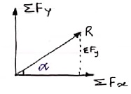
Resolution of Force:-
Following 3 methods are used to resolve the force.
1. Orthogonal Resolution (Perpendicular resolution)
2. Non – perpendicular / Non – Orthogonal resolution
3. Resolution into two parallel components.
1. Orthogonal or Perpendicular Resolution:-
In this method, single force is split up into two components which are perpendicular to each other along x direction & y direction.
Consider Force F as shown below, which makes an angle (1) with x-axis.
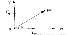
Then, Fx = Horizontal component of force F along x dirn
Fy = Vertical component of force F along y dirn.
θ = angle made by force F with x-axis. & angle between X & Y axis is 900
Now, let’s draw a perpendicular to X axis at point A. This perpendicular will intersect F at point B as shown below.
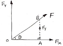
In right angle Δ OAB,
Sin θ = AB / OB = Fy / F & Cos θ = OA / OB

 Sin θ = Fy / F Cos θ = Fx / F
Fy = F Sin θ Fx = F Cos θ
……y component of force ……x component of force
Following are the different cases of resolution of Force into two perpendicular components.
Sign Conventions:
1. Component acting towards right are positive & towards left are considered as negative.

 +ive -ive
2. Component acting upward are positive & acting downward are considered as negative.


+ive -ive
Case:- ( Force acting away from point )
 (a) Force in 1st quadrant ( b ) Force in 2nd quadrant


 F Sin θ F F F Sin θ


F Cos θ -F Cos θ
Fx = F Cos θ Fx = - F Cos θ
Fy = F Sin θ Fy = F Sin θ
(c) Force in IIIrd quadrant ( d ) Force in IVth quadrant


 - F Cos θ F Cos θ
F - F Sin θ - F Sin θ F
Fx = - F Cos θ Fx = F Cos θ
Fy = - F Sin θ Fy = - F Sin θ
Cases of Resolution (force acting towards the point ) :-
( a ) Force in 1st quadrant ( b ) Force in 2nd quadrant
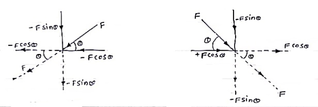
Fx = - F Cos θ Fx = F Cos θ
Fy = - F Sin θ Fy = - F Sin θ
(c) Force in 3rd quadrant ( d ) Force in 4th quadrant
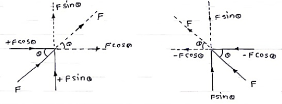
Fx = F Cos θ Fx = - F Cos θ
Fy = F Sin θ Fy = F Sin θ
Moment of a force
Moment:-The turning effect produced by a force on the body on which it acts is called as Moment.
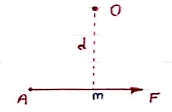 Moment of force about any point is the product of magnitude of force and perpendicular distance of force from the point about which moment is to be taken.
Let force F is applied at point A as shown & O is any point about which we want to take moment.
Thus from point O, draw OM line perpendicular to the line of action of force.
OM = d = Perpendicular distance between Force & point O.
Moment = M = F x d
Graphical representation of Moment:-
- Select suitable scale to locate the force graphically.
- Draw a line parallel to line of action of force. Length of this line can be calculated from selected scale.
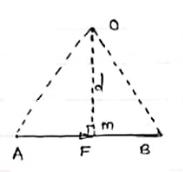 - Length of a line will be equal to magnitude of force. In the figure, Force F is represented by line AB.
- Now let O is the moment centre &
OM = d = perpendicular distance
By definition, Mo = F xd
Now join OA & OB, then
In Δ OAB
Area (ΔOAB) = ½ x AB x OM
2 (Area of ΔOAB) = F xd = Mo
Thus the moment of any force about any point is numerically equal to twice area of triangle in which base represents force & height represents the perpendicular distance.
Varignon’s Theorem
It states that if number of forces is acting simultaneously on a body, the algebraic sum of moments of all the forces about any point is equal to moment of their resultant about same point.
Mathematically,
∑(F x d) = (R x X)
Where, F = All forces acting on a body
d = ḻlar distance
R = Resultant of all forces
X = ḻlar distance of Resultant force about a point where moment is taken.
Use:- This theorem is useful to calculate or find the position or location of Resultant of non-concurrent force system.
Equations of Equilibrium
1. If the body moves in any direction, it means that there is a resultant force acting on it. In other words, the horizontal component of all the forces (Σ H) and vertical component of all the forces (ΣV) must be zero. Mathematically,
Σ H = 0 and Σ V = 0
2. If there is rotation of body, without moving, that means there is couple acting. In other words, the resultant moment of all the forces (Σ M) must be zero. Mathematically,
Σ M = 0
3. If the body moves in any direction and at the same time it rotates about itself, if means that there is a resultant force and also a resultant couple acting on it. In other words, horizontal component of all the forces (Σ H), vertical component of all the forces (Σ V) and resultant moment of all the forces (Σ M) must be zero. Mathematically,
Σ H = 0 Σ V = 0 and Σ M = 0
4. If the body is completely at rest it means there is no force nor any couple acting on it. A little consideration will show, that in this case the following conditions are already satisfied:
Σ H = 0 Σ V = 0 and Σ M = 0
The above-mentioned equations are known as the conditions/equations of equilibrium.
Thus, the equations of equilibrium for two-dimensional coplanar force system are given by considering that the particle is present in x-y plane as shown in fig. Below, then the force can be resolved into i and j components.
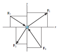
For equilibrium, the forces must add on to produce a zero-force output, i.e.,
Σ F = 0
ΣFxi + Σ Fy j = 0
Thus, for satisfying this vector equation, the x and y component must be zero as mentioned in earlier points. Hence,
ΣFx= 0
ΣFy= 0
Thus, for solving two-dimensional coplanar force problems using conditions of equilibrium, we can follow the below-mentioned procedure.
Free-Body Diagram.
• In any orientation, establish x and y axes.
• Then mark all the known and unknown forces in figure.
• Unknown forces are also assumed and plotted.
Equilibrium equation
• Apply the equations of equilibrium, ΣFx= 0 and Σ Fy = 0.
• The forces are directed as positive for those along positive axis and vice-versa.
• If the resultant comes out to be negative value, it means that the direction needs to be reversed for that is already considered.
As we know, the sufficient case for stating equilibrium for a body under combination of forces is Σ F = 0.
For any three-dimensional force system, as shown in Fig. Below, we can resolve the forces into their respective i, j, k components, so that
ΣFxi + Σ Fy j + ΣFz k = 0
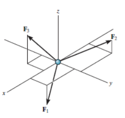
To satisfy this equation we require,
ΣFx= 0
ΣFy= 0
ΣFz= 0
These three equations state that the algebraic sum of the components of all the forces acting on the particle along each of the coordinate axes must be zero. Using these equations mentioned we can solve for maximum three of the unknowns, shown by coordinate direction angles or magnitudes of forces shown on the particle’s free-body diagram.
For solving three dimensional problem we can use the following procedure.
Free Body Diagram:
• In any orientation, establish x and y axes.
• Then mark all the known and unknown forces in figure.
• Unknown forces are also assumed and plotted.
Equations of Equilibrium
• Apply the equations of equilibrium, ΣFx= 0, Σ Fy = 0 and ΣFz= 0.
• Initially we can display as a Cartesian vector if it becomes to solve the problem regularly, substitute these vectors into Σ F = 0 and then set the i, j, k components equal to zero.
• If the resultant comes out to be negative value, it means that the direction needs to be reversed for that is already considered.
Friction and its effects on bodies
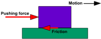
‘Frictionis a force that resists motion of sliding or rolling of one object moving relative to another. It is a result of the electromagnetic attraction between the charged particles of two touching surfaces. We find and use it everywhere and every day whenever objects come into contact with each other. Although it always acts in the always acts in the direction opposite to the way an object wants to slide.
For example, we use car brakes if we want to stop or slow down because of the friction created between the brakes and wheels that slow/stop the car down.
Factors Affecting Friction
The force of friction may alter depending on the following factors that affect it:
- When two smooth surfaces are in contact, then the degree of friction between them is small because the interlocking between smooth surfaces is less.
- When two rough surfaces in contact, then the degree of friction between them is large because the interlocking of between rough surfaces is too much.
- It also depends on the weight of the object or on the amount of force applied on the surface by the object.
Rolling Friction
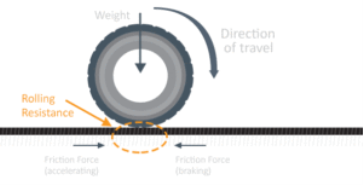
‘Rolling friction’ is the force that resists motion when an object rolls on a surface. Technically it’s not friction; its ‘rolling resistance’ since when a body rolls perfectly upon a surface, on paper, there is no sliding friction between that objects and surface. But due to elastic properties in real life, both the bodies and the surface experience deformations due to contact between the bodies. Since the surface of contact is very small in real life hence the net normal force is also small and it is not enough like the static friction to prevent a body from sliding and keep it stationary and static friction increases with the increase in the external force; therefore rolling friction is usually less than the static.
Sliding Friction
‘Sliding friction’ is the frictional force between two surfaces that are rubbing against each other. It’s a very easy and common concept. It’s hard to find a perfectly smooth surface in the real life, therefore when an object slides on any surface, it undergoes a backward force because of the relative motion between the two adjacent surfaces. It always acts against the motion. For a static situation, the applied force that tries to slide the object is always equal to the force of friction acting on the object. There comes a certain moment that the object starts moving in the direction of the external force. This happens when we gradually increase the applied force. The force of friction that acts against the motion remains constant.
Fluid Friction
When fluid layers are moving relative to each other, a type of friction occurs which is known as ‘fluid friction’. The internal resistance to the flow of fluids is termed ‘viscosity’; in simple terms, the viscosity is nothing but ‘thicknesses of a fluid.
Effects of Friction
- It produces heat that helps in heating parts of any object or to warm ourselves.
- It also causes loss in power.
- It produces noise during any kind of operation.
- It’s because of friction that we’re able to walk, run, play, etc.
Two parallel forces, General case of parallel forces in a plane, Centre of parallel forces, Centre of gravity, Centre of mass, Centroids of curves, areas and volumes – regular and composite, Pappus’s theorems, Equilibrium of distributed forces in a plane, Applications of the concept of centroid in engineering practice.
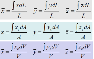
Centroids of curves, areas and volumes – regular and composite
Geometrical property of a body
Body of uniform density
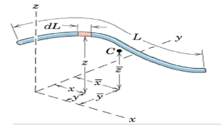
Centroid and CM coincide

Lines: Slender rod, Wire
Cross-sectional area = A
ρand A are constant over L
Dm = ρAdL
Centroid and CM are the same points

Areas:
Body with small but constant thickness t
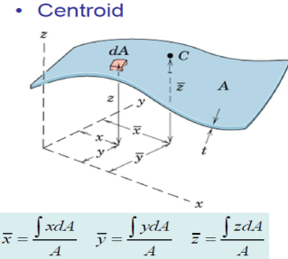
Cross-sectional area = A
ρ and A are constant over A
Dm = ρtdA
Centroid and CM are the same points

Volumes:
Body with volume V
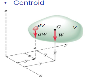
ρconstant over V
Dm = ρdV
Centroid and CM are the same point
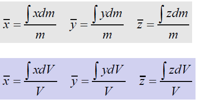
Numerator = First moments of Volume
Centroids of Lines, Areas, and Volumes
1. Order of Element Selected for Integration
2. Continuity
3. Discarding Higher Order Terms
4. Choice of Coordinates
5. Centroid Coordinate of Differential Elements
Centroid application
An object of any shape will be balance perfectly on its centroid.
OROn any point along the vertical line that passed through centroid, the object remains balanced.
Engineering application:-
In construction to properly balance structure with minimum stress.
Coplanar Parallel Force System
Parallel forces can be in the same or in opposite directions. The sign of the direction can be chosen arbitrarily, meaning, taking one direction as positive makes the opposite direction negative. The complete definition of the resultant is according to its magnitude, direction, and line of action.
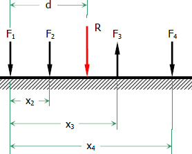
R=ΣF=F1+F2+F3+...R=ΣF=F1+F2+F3+...
Rd=ΣFx=F1x1+F2x2+F3x3+...
Centre of gravity
Centre of gravity, in physics, an imaginary point in a body of matter where, for convenience in certain calculations, the total weight of the body may be thought to be concentrated. The concept is sometimes useful in designing static structures (e.g., buildings and bridges) or in predicting the behaviour of a moving body when it is acted on by gravity.

When a drum is stood on end, its centre of gravity (CG) is firmly supported, and the drum is in stable equilibrium (A). If the drum is tilted slightly to either side (B), the pull of gravity on this centre creates a torque, or turning force, around the new point of support and pulls the drum back to the stable position. A drum balanced on its rim (C) is in unstable equilibrium. Even a tiny displacement (D) will create a torque that will turn the drum farther from the unstable position.
In a uniform gravitational field the centre of gravity is identical to the centre of mass, a term preferred by physicists. The two do not always coincide, however. For example, the Moon’s centre of mass is very close to its geometric centre (it is not exact because the Moon is not a perfect uniform sphere), but its centre of gravity is slightly displaced toward Earth because of the stronger gravitational force on the Moon’s near side.
The location of a body’s centre of gravity may coincide with the geometric centre of the body, especially in a symmetrically shaped object composed of homogeneous material. An asymmetrical object composed of a variety of materials with different masses, however, is likely to have a centre of gravity located at some distance from its geometric centre. In some cases, such as hollow bodies or irregularly shaped objects, the centre of gravity (or centre of mass) may occur in space at a point external to the physical material—e.g., in the centre of a tennis ball or between the legs of a chair.
Published tables and handbooks list the centres of gravity for most common geometric shapes. For a triangular metal plate such as that depicted in the figure, the calculation would involve a summation of the moments of the weights of all the particles that make up the metal plate about point A. By equating this sum to the plate’s weight W, multiplied by the unknown distance from the centre of gravity G to AC, the position of G relative to AC can be determined. The summation of the moments can be obtained easily and precisely by means of integral calculus.
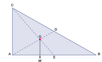
Centre of gravity. The red dot is the centre of gravity G.
The centre of gravity of anybody can also be determined by a simple physical procedure. For example, for the plate in the figure, the point G can be located by suspending the plate by a cord attached at point A and then by a cord attached at C. When the plate is suspended from A, the line AD is vertical; when it is suspended from C, the line CE is vertical. The centre of gravity is at the intersection of AD and CE. When an object is suspended from any single point, its centre of gravity lies directly beneath that point.
Centre of mass
The centre of mass is a position defined relative to an object or system of objects. It is the average position of all the parts of the system, weighted according to their masses.
For simple rigid objects with uniform density, the center of mass is located at the centroid. For example, the center of mass of a uniform disc shape would be at its center. Sometimes the center of mass doesn't fall anywhere on the object. The center of mass of a ring for example is located at its center, where there isn't any material.

Figure 1: Center of mass for some simple geometric shapes (red dots).
For more complicated shapes, we need a more general mathematical definition of the center of mass. It is the unique position at which the weighted position vectors of all the parts of a system sum up to zero.
What is useful about the center of mass
The interesting thing about the center of mass of an object or system is that it is the point where any uniform force on the object acts. This is useful because it makes it easy to solve mechanics problems where we have to describe the motion of oddly-shaped objects and complicated systems.
For the purposes of calculation, we can treat an oddly-shaped object as if all its mass is concentrated in a tiny object located at the center of mass. We sometimes call this imaginary object a point mass.
If we push on a rigid object at its center of mass, then the object will always move as if it is a point mass. It will not rotate about any axis, regardless of its actual shape. If the object is subjected to an unbalanced force at some other point, then it will begin rotating about the center of mass.
How can we find the center of mass of any object or system
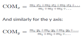
In general the center of mass can be found by vector addition of the weighted position vectors which point to the center of mass of each object in a system. One quick technique which lets us avoid the use of vector arithmetic is finding the center of mass separately for components along each axis. I.e.:
For object positions along the x axis:
Pappus's Centroid Theorem
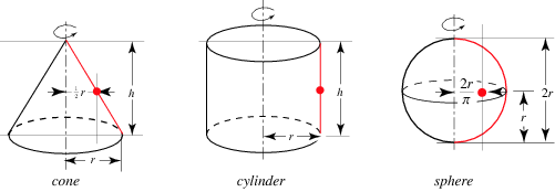
The first theorem of Pappus states that the surface area s of a surface of revolution generated by the revolution of a curve about an external axis is equal to the product of the arc length s of the generating curve and the distance d1 travelled by the curve's geometric centroid  ,
,

|
The following table summarizes the surface areas calculated using Pappus's centroid theorem for various surfaces of revolution.
Solid | Generating curve |  |  |  |
Cone | Inclined line segment |  |  |  |
Cylinder | Parallel line segment |  |  |  |
Sphere | Semicircle |  |  |  |
|
|
|
|
|

Similarly, the second theorem of Pappus states that the volume v of a solid of revolution generated by the revolution of a lamina about an external axis is equal to the product of the area A of the lamina and the distance d2 travelled by the lamina's geometric centroid  ,
,

|
The following table summarizes the surface areas and volumes calculated using Pappus's centroid theorem for various solids and surfaces of revolution.
Solid | Generating lamina |  |  |  |
Cone | Right triangle |  |  |  |
Cylinder | Rectangle |  |  |  |
Sphere | Semicircle |  |  |  |
Discrete Distributed Force
If the loading on the object is a set of parallel discrete forces, the resultant force is simply the sum of all the forces, or
FR = ΣFi
In the previous section, three scalar equations were derived that determine the position r of a force FR that represents the force resultant to a system of discrete forces. If all forces are parallel to the y direction then the three scalar equations simplify to
Σ(zF) = z' ΣF
Σ(xF) = x' ΣF
Here x and z are the Cartesian coordinates of the individual forces, and x' and z' are the coordinates of the force
Rearranging these two equations gives

If the forces are further restricted so that they all lie in the x-y plane, then z' = 0 and only the second equation applies.
Continuous Distributed Force
If instead of a system of point loads, consider a continuous distributed force f(x) that acts in the x-y plane and is parallel to the y axis, then through calculus the second equation (x') above becomes

The force resultant is simply the force magnitude FR given by

The force magnitude FR is located a distance x' from the origin.