Unit 4
Curvilinear translation
Kinematics of curvilinear translation – components of displacement, velocity and acceleration
When a particle moves along a curved path, then motion of the particle is said to be curvilinear.
Basic terminology used to describe curvilinear motion: -
- Position vector: - (
 )
)
- Consider that particle is moving along the curve as shown in figure.
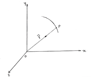
b. Let ‘P’ is the position of particle at any time instant ‘t’.
c. Let we have fixed reference axes x, y,z as shown.
d. The line ‘OP’ represents the position of particle &it is known as position vector of particle at time ‘t’.
 Position vector
e.  = xi + yj + zk and
 - Magnitude of position
2. Displacement and distance:
- Consider that particle is moving along the plane curve P-P’ as shown in figure.
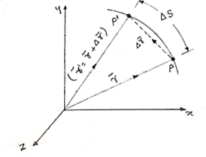
- Let particle is located at point P at time instant ‘t’.
Position of particle at point P is given by vector  . Now after time (t + ∆t), let particle is moved to a new position P’. This position of particle is given by the vector (
 )
)
- The vector joining P & P’ is ∆
 . (dashed line)
∆ = change of position of particle during the time interval ∆t.
∆ = displacement of particle.
- The distance travelled by the particle along the curve from point P to P’ is ∆s. This is measured along the curved path & is scalar quantity.
3. Velocity :
In above figure ∆ = displacement vector
∆r = displacement of particle (magnitude).
∆t = time taken by particle to move from P to P’.
Avg. Velocity =  = vavg.
- When the time interval approaches to zero, ∆t → 0.
Instantaneous velocity at P will be,
V = 
V = 
Speed = 
4. Acceleration: -
Avg. Acceleration a = 
For very small interval of time ∆t → 0
Thus a =  &
&
The acceleration at point P = 
(Instantaneous acceleration)
Normal and tangential acceleration
- We know that, velocity of particle is always tangential to the path along which it is moving.
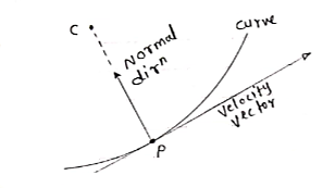
(consider a particle moving along curve & is located at point P at any instant ‘t’)
So the tangent drawn at that point (at point P) represents the tangential direction. &The direction which is perpendicular to the velocity vector (or tangent at P) & passing through center of curvature is known as normal direction.
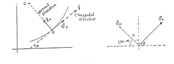
- Let us consider the particle moving along a curve contained in the plane as shown in figure above.
Let P is the position of the particle at a given instant. Now, let us attach unit vector  at point P.
  is along tangential direction
  is along normal direction.
 = unit vector along tangential direction
 = unit vector along normal direction.
- Unit vectors can be written as
 &
& =
= 
Differentiating above equation w.r.t. Ø
We get,

 --------- (2)
- Velocity components
As the velocity is always tangential to the path along which partial moves, Then,
Tangential component of velocity is equal to velocity itself and normal component will be zero.
vT= v
vN= 0
The velocity vector of particle is tangent to path.
It will be 
- Acceleration of particle

 -----(3)
But  by double chain rule
 --(4)
--(4)
- Now let us find the value of

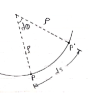
Consider particle moving along curve is at Pat time t. Then after small time interval ∆t, particle attains new position at P’. During this it covers ‘ds’ distance along the curve.
Let C = center of radius of curvature.
 = radius of curvature of curved path
- Then arc length = radius × angle subtended by arc
Ds =  ×dØ
×dØ

Putting above value in equation (4), we get,

Putting this value in equation (3)


 --------acceleration vector
Where,
 & -----tangential component of acceleration
 ------normal component of acceleration
Magnitude of acceleration (total)

Direction of total acceleration is,
Tanα =  where α = angle made by acceleration with normal direction
- aN is always directed toward center of curvature.
- aT reflects the change in speed of particle.
- aN reflects the change in direction of motion.
- When
 become infinity at inflection point then aN = 0
Motion of a projectile – projection on horizontal and inclined surfaces
When a particle is freely thrown in the air along any direction other than vertical it follows it follows the parabolic path .The motion of a particle along this parabolic path is called as projectile motion.
i.e. when we project the particle in the space, its motion is a combination of horizontal & vertical motion. This motion is called as projectile Motion.
Wind Resistance, curvature & rotation of the earth affects the actual path.
But these parameters are neglected.
- The path Traced by projectile is called as Trajectory.”
- The motion of projectile in Horizontal direction is uniform motion.
- Ax = Horizontal component of acceleration = 0
- The acceleration in vertical direction is affected by gravity. Thus motion in y direction is considered as “Motion under gravity.”
- :.
 y = -
y = -
Basic Terms involved in the projectile Motion
1) Time of flight :- (t)
- The time by the projectile to move from point of projection to the point of target is called as “Time of flight.”
- It is the total time during which projectile remains in space.
2) “Horizontal Range” :- (R)
It is Horizontal distance from point of projection the point of target. OR It is Horizontal distance bet/n point of projection & point of landing.
3) Maximum Height :- (H) or (Hmax)
It is the vertical distance bet/n the point of projection and the point © where the vertical component of velocity is zero.
4) Angle of projection :(  )
)
- It is the angle made by velocity with the Horizontal.
- If velocity is directed up the horizontal, then it is called as angle of elevation.
-If the velocity is directed down the Horizontal, then it is called as angle of depression.
5) Trajectory:-
It is the path traced by a projectile during its motion. It is parabolic in nature.
Projectile on Horizontal plane
Consider a projectile projected from point A with
u= initial velocity of projection &
 =Angle of projection.
Let t = total time of flight.
Thus projectile will land at point b after time‘t’ Both point A& B are Qn H.P
Diagram
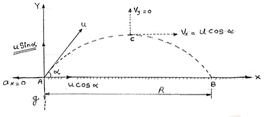
As the air resistance is neglected, the motion in X-direction is uniform motion & y dirn motion is Motion under Gravity”.
a) Time of flight (t)
t 2 u sin /
/
b) Horizontal Range (R)
R = u2. Sin2 /
/
c) Maximum Range (R max)
For maximum Range angle of projection must be 45
R max = u2/
d) Maximum Height
H = u2. Sin2 /2
/2
Derivation of path Equation
Vx= u cos = constant.
Vy = u sin 
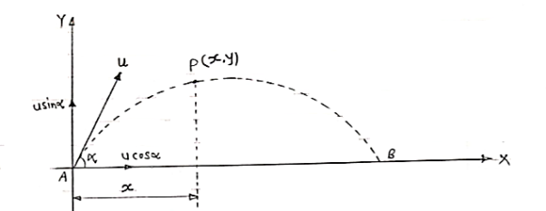
Consider a particle projected from A with initial velocity ‘u’ & angle of projection ‘ ’.
’.
Let after time ‘t’ , the particle has reached at point p (x,y).
Consider the motion of projectile in X dirn (VM) :- [ A p]
p]
S= velocity * time
X = u cos . t1
. t1
:. t1 = X/ u cos  . t1
. t1
:. t1 = X/ u cos . --------- (1)
Consider the motion of projectile in y dir/n (m. U.G) [ A p]
p]
:. Sy= uyt1- ½  t2
t2
Y = u sin  .t1 – 1/2
 t12
t12
From eq/n (1), put the value of time t1
:. y = usin  .(x/ucos
 .) – ½
  (x/ u-cos
 .)2
.)2
:. y = X. Tan - gx2/u2 cos2
:. y X. Tan - gX2/2u2 cos2
Projectile on Inclined plane
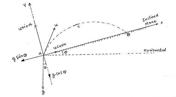
Let projectile is projected from point A.
Let angle projection with (inclined) plane.
 = Angle of inclined plane with Horizontal.
Now let us select X axis along the inclined plane and y –axis perpendicular to the inclined plane.
:. X component of velocity = u cos
:. Y - ----- -------------------- u sin 
Similarly for gravitation Acc/n ‘g’
X component = g sin
y component = g cos
a) Time of flight (t) b) Range along the plane (R)
t= 2u. Sin /g cos
  R= 2 u2 sin
 / g cos2
  . Cos (
 +
+ )
)
c) Maximum Range (Rmax) d)Max. Height (lar to plane)
Rmax = u2/g (1+sin ) H = u2 sin2
 / 2g. Cos
*Special cases of projectile*
*projectile projected with Horizontal velocity:-*
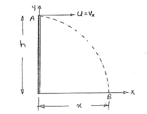 X motion
Consider motion A  B
B
(V.M)
X = u*t
Consider Motion (y- motion)
From A B (M.V.G)
S = ut + ½ gt2
h= 0 + ½gt2
:. t=  2h/g
2h/g
:. Horizontal distance, = X = u 
Y = x tanx - gx2/u2 cos2  -eqn of trnjectory
But  = 0 At point A.
:. –h = -y = 0 - gx2/2u2
:. h = gx2 / 2u2
*for given values of u, two angle gives us the same Range.
 1 =
1 = 
 2 = π/2 -
Alembert’s principle in curvilinear motion and its applications
The principle of virtual work states that the sum of the incremental virtual works done by all external force Fi acting in conjunction with virtual displacements siof the point on which the associated force is acting is zero:

This technique is useful for solving statics problems, with static forces of constraint. A static force of constraint is one that does no work on the system of interest, but merely holds a certain part of the system in place. In a statics problem there are no accelerations. We can extend the principle of virtual work to dynamics problems, i.e., ones in which real motions and accelerations occur, by introducing the concept of inertial forces. For each parcel of matter in the system with mass m, Newton’s second law states that
F=ma:
We can make this dynamics problem look like a statics problem by defining an inertial force
F* = - ma
And rewriting equation (1.1.2) as
F total = F + F* = 0
Alembert’s principle is just the principle of virtual work with the inertial forces added to the list of forces that do work:

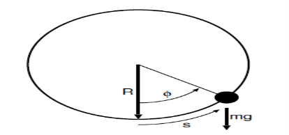
Figure 1.1.1: Sketch of bead of mass m sliding frictionless on a vertical hoop of radius R under the influence of gravity.
Mass falling under gravity
A trivial example would be a mass m falling under the effect of a constant gravitational field g. With z positive upward, the force on the mass is -mg and the work due to this force under vertical displacement 
The inertial force is  and the work is
Setting the sum of the two to zero gives us

From which we infer the expected result

Alembert’s principle offers no advantages over normal procedures in this case. However, it becomes more economical in problems with constraints.
Bead on frictionless vertical hoop
Figure 1.1.1 illustrates the slightly more interesting problem of a bead sliding frictionless around a vertically oriented hoop of wire. Here the force of gravity is not in the direction of motion. The component of gravity normal to the hoop does no work on the bead. Nor does the force of the hoop on the bead that constrains the bead to move in a circle. The work on the bead due to gravity for a small displacement  along the wire
The acceleration of the bead also has two components, a radial component
 Where the tangential velocity is
  and a tangential component
The radial component of the inertial force mv2=R does no work. However, the tangential component 
Does: 
Alembert’s principle thus gives us

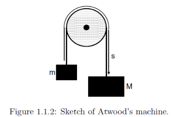
From which we get the governing equation

Applications of D’Alembert’s Principle
D’Alembert’s principle is based on the principle of virtual work along with inertial forces. The following are the applications of D’Alembert’s principle:
- Mass falling under gravity
- Parallel axis theorem
- Frictionless vertical hoop with a bead
Moment of momentum
Consider a rigid body in general plane motion as shown in figure.
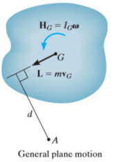
We have,

Taking moment at point A on both sides we get,

As the mass m of a rigid body and distance d of center of mass from point A is constant

The term  represents the total torque T on the particle at point A.
And  is the rate of change of moment of momentum.

This is the moment of momentum equation.
It is derived from the moment of momentum principle that states that the resulting torque acting on a rotating fluid is equal to the rate of chance of moment of momentum.

Integrating both sides

Where,
 = angular impulse
 = change in angular momentum
Work and energy in curvilinear motion
When a particle subjected to force F undergoes a displacement in the direction of the force, the force F will do work on the particle.
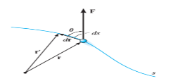
Consider a particle subjected to force F that causes the displacement of ds at an angle of  from the direction of force.
Let,
r = position vector of initial position
r’ = position vector of new position
Dr = r’ – r = displacement whose magnitude is ds
The component of forces in the direction of motion that causes the particle to displacement is given as 
As we know,
Work = Force x displacement

Where,  is the work done to displace the particle by ds
The work is a scalar quantity given by the dot product.

There are various types of work for different forces given below:
- Work of variable force
If a particle is subjected to variable force F that undergoes a displacement along its path with magnitude from  and
and  defined by the position vectors
  and
and  respectively and
  is the angle between the direction of force and the direction of displacement, as shown in figure, then the work done by the force F is given by

Where, F and  are defined as the function of position.
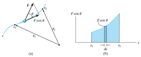
Then the area under this graph bounded by  and
and  represents the total work. (Fig. b)
2. Work of constant force
If a particle is subjected to constant force FC that undergoes a displacement along its path with magnitude from  and
and  defined by the position vectors
  and
and  respectively and
  is the constant angle between the direction of force and the direction of displacement, as shown in figure, then the work done by the force FC is given by


Then the area under this graph bounded by  and
and  (rectangle) represents the total work. (Fig b)
3. Work of weight
Consider a particle of weight W that moves along the path s from the position  to
to  defined by the position vector
  and
and  respectively.
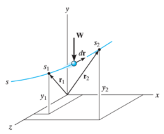
The displacement of a particle at any point intermediate on the path is given by

Since,

We have,


As weight is a constant force, hence,


4. Work of spring force
Consider an elastic spring that is elongated by distance ds on the action of force FS as shown below.

If a particle displaces from position  to
to  , then the work done is given by,


The trapezoidal region in the graph represents the total work done.
Principle of Work and Energy
The principle of work and energy states that, sum of the work done by all the forces acting on the particle is equal to the change in total energy (kinetic energy) of the particle.
Consider the particle located on the path that is defined relative to an inertial coordinate system as shown in figure below.
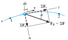
Let the particle has initial position  with speed
  and final position
  with speed
Let the particle has a mass m and is subjected to a system of external forces which is represented by the resultant force given below

The equation of motion for the particle in the tangential direction is given by

Applying the kinematic equation  and integrating both sides


Where  and
and  are the initial and final kinetic energies of the particle. Kinetic energy is always positive.
Rotation of a rigid body:
Kinematics of rotation – angular displacement, velocity and acceleration
Just by using our intuition, we can begin to see how rotational quantities like θ, ω, and α are related to one another. For example, if a motorcycle wheel has a large angular acceleration for a fairly long time, it ends up spinning rapidly and rotates through many revolutions. In more technical terms, if the wheel’s angular acceleration α is large for a long period of time t, then the final angular velocity ω and angle of rotation θ are large. The wheel’s rotational motion is exactly analogous to the fact that the motorcycle’s large translational acceleration produces a large final velocity, and the distance travelled will also be large.
Kinematics is the description of motion. The kinematics of rotational motion describes the relationships among rotation angle, angular velocity, angular acceleration, and time. Let us start by finding an equation relating ω, α, and t. To determine this equation, we recall a familiar kinematic equation for translational, or straight-line, motion:
v=v0+at
(Constant a)
Note that in rotational motion a = at, and we shall use the symbol a for tangential or linear acceleration from now on. As in linear kinematics, we assume a is constant, which means that angular acceleration α is also a constant, because
a = rα. Now, let us substitute v = rω and a = rα into the linear equation above:
rω = rω0 + rat.
The radius r cancels in the equation, yielding
ω = ω0 + at. (Constant a)
Where ω0 is the initial angular velocity. This last equation is a kinematic relationship among ω, α, and t —that is, it describes their relationship without reference to forces or masses that may affect rotation. It is also precisely analogous in form to its translational counterpart.
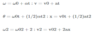
Starting with the four kinematic equations we developed in One-Dimensional Kinematics, we can derive the following four rotational kinematic equations (presented together with their translational counterparts):
Rotational | Translational | |
θ=¯ωtθ=ω¯t | x=¯vtx=v¯t | |
ω = ω0 + αt | v = vo + at | (constant α, a) |
θ=ω0t+12αt2θ=ω0t+12αt2 | x=v0t+12at2x=v0t+12at2 | (Constant α, a) |
ω2 = ω02+ 2αθ | v2 = vo2 + 2ax | (constant α, a) |
Table Rotational Kinematic Equations | ||
In these equations, the subscript 0 denotes initial values (θ0, x0, and t0 are initial values), and the average angular velocity ω¯ and average velocity v¯ are defined as follows:
ω=ω0+ω2 and v=v0+v2
Relations of kinematic parameters of linear and angular motions
The description of circular motion is described better in terms of angular quantity than its linear counterpart. The reasons are easy to understand. For example, consider the case of uniform circular motion. Here, the velocity of particle is changing – though the motion is “uniform”. The two concepts do not go together. The general connotation of the term “uniform” indicates “constant”, but the velocity is actually changing all the time.

A Rotating Body: Each particle constituting the body executes a uniform circular motion about the fixed axis. For the description of the motion, angular quantities are the better choice.
When we describe the uniform circular motion in terms of angular velocity, there is no contradiction. The velocity (i.e. angular velocity) is indeed constant. This is the first advantage of describing uniform circular motion in terms of angular velocity.
Relationship between Linear and Angular Speed
For simplicity, let’s consider a uniform circular motion. For the length of the arc subtending angle” at the origin and “r” is the radius of the circle containing the position of the particle, we have
s=rθ
Differentiating with respect to time, we have

Because dr/dt=0 for a uniform circular motion, we get v=ωr similarly, we also get a=αr where a stands for linear acceleration, while α refers to angular acceleration (In a more general case, the relationship between angular and linear quantities are given as v=ω×r, a=α×r+ω×v).
Rotational Kinematic Equations
With the relationship of the linear and angular speed/acceleration, we can derive the following four rotational kinematic equations for constant a and α
Compound pendulum
Pendulum, body suspended from a fixed point so that it can swing back and forth under the influence of gravity. Pendulums are used to regulate the movement of clocks because the interval of time for each complete oscillation, called the period, is constant. The formula for the period T of a pendulum is T = 2π√L/g, where L is the length of the pendulum and g is the acceleration due to gravity.
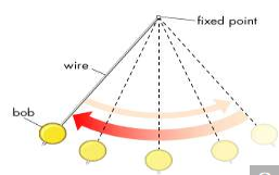
A simple pendulum consists of a bob suspended at the end of a thread that is so light as to be considered mass less. The period of such a device can be made longer by increasing its length, as measured from the point of suspension to the middle of the bob. A change in the mass of the bob, however, does not affect the period, provided the length is not thereby affected. The period, on the other hand, is influenced by the position of the pendulum in relation to Earth. Because the strength of Earth’s gravitational field is not uniform everywhere, a given pendulum swings faster, and thus has a shorter period, at low altitudes and at Earth’s poles than it does at high altitudes and at the Equator.
There are various other kinds of pendulums. A compound pendulum has an extended mass, like a swinging bar, and is free to oscillate about a horizontal axis. A special reversible compound pendulum called Kater’s pendulum is designed to measure the value of g, the acceleration of gravity.
Another type is the Schuler pendulum. When the Schuler pendulum is vertically suspended, it remains aligned to the local vertical even if the point from which it is suspended is accelerated parallel to Earth’s surface. This principle of the Schuler pendulum is applied in some inertial guidance systems to maintain a correct internal vertical reference, even during rapid acceleration. A spherical pendulum is one that is suspended from a pivot mounting, which enables it to swing in any of an infinite number of vertical planes through the point of suspension. In effect, the plane of the pendulum’s oscillation rotates freely. A simple version of the spherical pendulum, the Foucault pendulum, is used to show that Earth rotates on its axis. See also ballistic pendulum.
D'Alemberts principle in rotation,
D’Alembert’s principle, alternative form of Newton’s second law of motion, stated by the 18th-century French polymath Jean le Rond d’Alembert. In effect, the principle reduces a problem in dynamics to a problem in statics. The second law states that the force F acting on a body is equal to the product of the mass m and acceleration a of the body, or F = ma; in d’Alembert’s form, the force F plus the negative of the mass m times acceleration a of the body is equal to zero: F - ma = 0. In other words, the body is in equilibrium under the action of the real force F and the fictitious force -ma. The fictitious force is also called an inertial force and a reversed effective force.
Because unknown forces are more easily determined on bodies in equilibrium than on moving bodies, the force and stress analysis of machine components can usually be simplified by using inertial forces. When developing the formulas for the stresses in a rotating disk, for example, it is convenient to assume that a representative element in the disk is in equilibrium under the action of a system of radial and tangential forces produced by the stresses and an outward-acting inertial (centrifugal) force.
Resultant inertia force in rotation
Rotational inertia is a property of any object which can be rotated. It is a scalar value which tells us how difficult it is to change the rotational velocity of the object around a given rotational axis.
Rotational inertia plays a similar role in rotational mechanics to mass in linear mechanics. Indeed, the rotational inertia of an object depends on its mass. It also depends on the distribution of that mass relative to the axis of rotation.
When a mass moves further from the axis of rotation it becomes increasingly more difficult to change the rotational velocity of the system. Intuitively, this is because the mass is now carrying more momentum with it around the circle (due to the higher speed) and because the momentum vector is changing more quickly. Both of these effects depend on the distance from the axis.
Rotational inertia is given the symbol I. For a single body such as the tennis ball of mass m (shown in Figure 1), rotating at radius r from the axis of rotation the rotational inertia is
I = mr2, and consequently rotational inertia has SI units of kg⋅m2
Rotational inertia is also commonly known as moment of inertia. It is also sometimes called the second moment of mass; the 'second' here refers to the fact that it depends on the length of the moment arm squared.

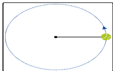
Figure 1: A tethered tennis ball rotating about a central point.
How does rotational inertia relate to Newton's 2ⁿᵈ law
Rotational inertia takes the place of mass in the rotational version of Newton's 2ⁿᵈ law.
Consider a mass m attached to one end of a massless rod. The other end of the rod is hinged so that the system can rotate about the central hinge point as shown in Figure 2.
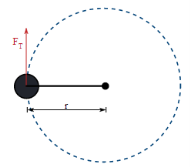

Figure 2: A mass rotating due to a tangential force.
We now start rotating the system by applying a tangential force FT, to the mass. From Newton’s 2ⁿᵈ law, FT=m(ra) this can also be written asNewton's 2ⁿᵈ law relates force to acceleration. In rotational mechanics torque takes the place of force. Multiplying both sides by the radius gives the expression we want.

This expression can now be used to find the behaviour of a mass in response to a known torque.
Principle of angular momentum in rotation,
Suppose an object of mass m is revolving around a circle of radius r with speed v about an axis passing through center O as shown in the figure.
The linear momentum of the object, p = mv.
The angular momentum of an object, L = linear momentum x perpendicular distance from the axis of rotation.
Or, L = p r
Therefore, L = m v r
Since v = w r, where w is the angular velocity of the object, the angular momentum can be written as
L = m (w r) r
Or, L = m r2 w
The equations above are the expressions for the angular momentum of the body. It is a vector quantity.
Angular Momentum Unit and Dimension
In CGS system, the unit of angular momentum is g cm2s-1 and in SI system, its unit is kg m2s-1.
The dimensional formula of angular momentum L is:
L = [M L0 T0] [M0 L T-1] [M0 L T0]
= [M L2 T-1]
Principle of Conservation of Angular Momentum
Principle of conservation of angular momentum states that,
If no external torque acts on a system, the total angular momentum of the system remains constant.
If I be the moment of inertia of a body about a given axis of rotation and w be its angular velocity, then I w = constant.
This equation represents the mathematical form of principle of conservation of angular momentum.
Proof
We know that the torque acting on a system is equal to the time rate of change of angular momentum of the system about that axis, i.e.
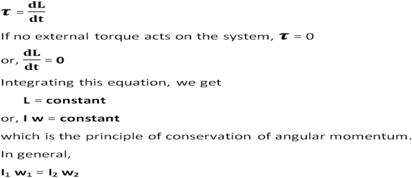
Above equation proves that, the angular momentum remains constant if no torque acts on the system.
Energy equation for rotating bodies
Kinetic Energy of Rotation: Things that roll without slipping have some fraction of their energy as translational kinetic and the remainder as rotational kinetic. The ratio depends on the moment of inertia of the object that’s rolling.
E(rotational)=1/2Iω2
Where ω is the angular velocity and I is the moment of inertia around the axis of rotation.
The mechanical work applied during rotation is the torque (τ) times the rotation angle (θ):
W=τθ
The instantaneous power of an angularly accelerating body is the torque times the angular velocity:
P=τω
Note the close relationship between the result for rotational energy and the energy held by linear (or translational) motion:
E(translational)=1/2mv2
.In the rotating system, the moment of inertia takes the role of the mass and the angular velocity takes the role of the linear velocity.
As an example, let us calculate the rotational kinetic energy of the Earth As the Earth has a period of about 23.93 hours, it has an angular velocity of 7.29×10⁻⁵ rad/s. The Earth has a moment of inertia, I = 8.04×1037 kg·m2. Therefore, it has a rotational kinetic energy of 2.138×1029 J.